Note: Descriptions are shown in the official language in which they were submitted.
CA 02283757 1999-09-13
WO 98/43456 PCT/F198/00241
1
MORILFi NE'TWORKS US1N(:, A'I'M SWI'f'CHING
FIELD OF THE INVENTION
The invention relates to telecommunication networks and
particularly to mobile networks using ATM (Asynchronous Transfer Mode)
transfer systems. The invention also relates to the control of mobility and
call
control functions in ATM systems.
BACKGROUND OF THE INVENTION
Two of the current development trends in telecommunication are
mobile communication and broadband networks. The term broadband typically
refers to a bit rate higher than 2 Mbit/s. Narrowband usually refers to a bit
rate
of 64 kbit/s or lower. Bit rates from 64 kbit/s to 2 Mbit/s are sometimes
referred to as wideband. Broadband networks are attractive for at least two
(compatible) reasons:
1) A single broadband network bearer divided among a plurality of
users, few or none of whom need the whole bandwidth alone, can offer
advantages concerning flexibility and the building of transfer systems.
2) Information to be transferred on separate transfer channels
possibly demand broadband channels. Users need new high-quality services,
which in turn require high bit rates. Such services include e.g. video
conferences, high-speed data transmission, etc. A common denominator for
these services is multimedia, which combines image, voice and data into one
service.
Due to its numerous strengths, ATM (Asynchronous Transfer Mode)
is chosen as the transmission technique in various standardized B-ISDN
(Broadband Integrated Services Digital Network) protocol structures. In this
connection the term 'transmission' refers to the use of ATM switching and
multiplexing techniques in a data link layer (i.e. an OSI Layer 2, hereinafter
referred to as an ATM layer) relaying end user traffic from a source to a
destination within a network. Between the source and the destination are
established virtual connections, which requires the network to have switching
functions. Signalling and user information are normally conveyed by different
virtual connections in an ATM layer. A virtual connection is identified in the
ATM layer by a Virtual Path Identifier VPI and a Virtual Channel Identifier
VCI.
In ATM information is conveyed segmented in fixed-length cells, the
number of the cells in a time unit being proportional to the user's bandwidth
CA 02283757 2006-05-23
2
requirements. Each 53-octet cell is divided into a 5-octet
header and a 48-octet information field.
The main purpose of the header is to identify a
connection number for a cell sequence providing a virtual
channel for a particular call. A plural number of virtual
paths, which are multiplexed in the ATM layer, can be connected
to one and the same physical layer ( i. e. an OSI Layer 1) , each
path being identified by an 8-bit VPI at a User-to-Network
interface UNI and a 12-bit VPI at a network-node interface.
Each path can comprise a plural number of virtual channels,
each of which is identified by a 16-bit VCI. The header can
also comprise other fields, such as a Header Error Control HEC,
a Generic Flow Control GFC, a Cell Loss Priority CLP and a
Payload Type PT.
The User-to-Network interface UNI between an ATM user
terminal and an ATM switch (a private UNI) and between private
and public ATM networks (a public UNI), together with a UNI
signalling (and an ATM cell) related thereto, are defined at
least in the following recommendations:
[1] ATM User-to-Network Interface Specification, version
3.1, ATM Forum, 1994;
[2] ATM User-to-Network Interface (UNI) Signalling
Specification, version 4.0, ATM Forum, June 1994;
[3] ITU-T Recommendation Q.2931 (1994) Broadband
Integrated Services Digital Network (B-ISDN), Digital
Signalling System No. 2 (DSS 2), User-to-Network Interface
(UNI) Layer 3 Specification for Basic Call/Connection Control.
ITU-T.
In mobile networks, radio interfaces have
conventionally been narrowband. Mobile network transmission
systems have conventionally been implemented with circuit-
switched connections using a star or tree network
configuration. In order to increase the capacity and
flexibility of transmission systems, different broadband packet
CA 02283757 2006-05-23
3
switched transmission systems have also been proposed for
mobile networks, e.g. in WO 9319559, WO 9400959 and EP 0366342.
EP0426269 describes a mobile system in which base stations are
connected via routers to ATM network switches. Virtual
connections controlled by the base stations are established
between the base stations through the ATM network. Elementary
mobility management is based on routing tables, which are
maintained at base stations and in ATM switches and updated as
subscribers move. GB2268359 and EP 679042 describe an ATM-
access network in which there are permanent ATM virtual
connections (to speed up the call set-up) between base stations
and a mobile network interface, said connections being
allocated for each call separately.
A possible future development trend is that mobile
systems will have a broadband radio interface. In this case
the transmission system of the mobile system should also be
broadband, a potential alternative being provided by the ATM
technology.
A third development trend is the introduction of
wireless data transmission (wireless ATM) and mobility
management into ATM networks. However, a problem arising from
this is that current B-ISDN and ATM standards in no way support
the mobility management, subscriber authentication, call
control, etc., required by mobile communication. To introduce
into the ATM network such supplementary characteristics
required by mobile communication would therefore seem to
require considerable development and standardization of and
significant changes to the existing ATM systems. The
implementation of wireless ATM would thus become a slow and an
expensive process.
BRIEF SUMMARY OF THE INVENTION
An object of the invention is to implement an ATM-
transmission or an ATM-access network in a more flexible manner
CA 02283757 2006-05-23
4
than before in mobile network architectures that conventionally
use circuit-switched transmission systems.
Another object of the invention is to add wireless
transmission and mobility to the ATM network, without
significant changes to the existing ATM networks and standards.
According to a broad aspect of the present invention
there is provided a telecommunication network comprising mobile
stations (MS), base stations (BTS), at least one switching
network element (BSC, MSC) . Also comprising a call control
unit for implementing call control and mobility management
sigalling of a mobile communication network, and an ATM
switching matrix for a dynamic switching of virtual ATM
transmission connections between the base stations and the at
least one switching network element. The telecommunication
network is characterized in that the ATM switching matrix is
arranged in the at least one switching network element (MSC,
BSC). The switching network element further comprises an
internal interface unit connected to the call control unit and
to the ATM switching matrix for controlling the ATM switching
matrix through the interface unit by call control functions of
the call control unit.
Another aspect of the invention is a wireless ATM
network comprising mobile stations and at least one ATM switch
to which base stations are connected through a network-to-user
interface UNI. The invention is characterized by the ATM
network having at least one switching network element of
another telecommunication network, such as a mobile network, to
perform call control and switching control; said switching
network element being provided with an ATM switching function,
which is controlled through an internal interface by the call
control of the network element, for a dynamic switching of
virtual ATM transmission connections between the base stations
and said at least one switching network element.
CA 02283757 2006-05-23
4a
According to a further broad aspect of the present
invention there is provided a switching network element of a
mobile communications network. The switching network element
comprises a call control unit for implementing call control and
mobility management signaling of a mobile communication
network. The switching network element comprises an ATM
switching matrix for a dynamic switching of virtual ATM
transmission connections to base stations and an internal
interface unit connected to the call control unit and to the
ATM switching matrix interface for controlling ATM switching
through the interface unit by call control functions of the
call control unit.
In the invention a network element of a
telecommunication network, such as a mobile network, which in
conventional telecommunication network architecture performs
the switching of circuit-switched connections, is provided with
ATM switching functions. The ATM switching functions are
controlled by the same call control and switching control
functions that are conventionally used e.g. for controlling a
TDM switching field in a PLMN network element. In a minimum
configuration, an ATM switching field provided with a suitable
control interface is simply arranged in place of or parallel
with the TDM switching field. As a result, the switching
network element is, from the point of view of a physical and a
logical connection layer, one of the nodal points of the ATM
network. As regards for instance PLMN-level signalling,
mobility management and call control, the change is
a transparent one, so said functions can be carried
out applying solutions based on existing mobile networks
and PLMN network elements, with only slight modifications.
This reduces costs and enables even existing PLMN networks
to be provided with an ATM transmission system. The
invention also makes continuous evolution of the trans-
mission system in telecommunication networks possible, because
CA 02283757 1999-09-13
WO 98/43456 PCT/F198/00241
the use of ATM transmission can be further extended to other network
elements, without changes being needed to higher level system solutions.
A telecommunication network element of the invention may
comprise both a conventional TDM switching field and a new ATM switching
5 field parallel with each other. This provides an advantageous solution for
instance in a network evolution phase in which the telecommunication network
comprises base stations or other network elements using both circuit-switched
transmission and ATM transmission. The switching network element can in
this situation be arranged to switch either a virtual ATM connection or a
circuit-
switched connection to a base station or other network element, depending on
whether said base station or other network element supports ATM
transmission or not.
The telecommunication network element of the invention functions
in ATM layers according to ATM standards, signalling with other ATM devices
(user terminals or ATM switches) in accordance with e.g. UNI signalling. The
invention thus requires no changes to the ATM network signalling and its
operation.
PLMN network elements of the invention can also be used for
introducing mobility management and call control into a wireless ATM network.
One or more PLMN network elements are arranged as a part of the ATM
network and call control signalling is transparently transmitted through the
ATM network. Since also the switching of virtual connections is performed in
the PLMN network element, the rest of the ATM network is not required to
have any features related to mobility management.
In a preferred embodiment of the invention, the PLMN element is
connected to the ATM network through a UNI interface. The base stations are
correspondingly connected to the ATM network through a UNI interface. The
configuration of the ATM network can vary considerably. For instance, it is
possible that each base station is connected through a UNI interface direct to
a mobile services switching centre by an ATM switching function. For the
mobile services switching centre the base stations are then ATM user
terminals to which virtual connections can be switched. It is also possible
that
the base stations and the mobile services switching centre are connected to a
base station controller by an ATM switching function through a UNI interface.
For the base station controller the base stations and the mobile services
switching centre are then ATM user terminals between which virtual
CA 02283757 2006-05-23
6
connections can be switched. Both a mobile services switching
centre and a base station controller may simultaneously
comprise an ATM switching function.
The invention allows all special network elements and
special functions related to wireless communication to be
implemented into cellular radio networks using previously
designed network elements and solutions. The designing of
special solutions for a wireless ATM is thus avoided. The
cellular network elements concerned are connected to the ATM
network through a standard UNI interface, but the signalling
between the cellular network elements takes place either
transparently through the ATM network via said permanent
virtual connections or separate signalling connections. The
signalling related to wireless communication thus causes no
changes in a standard ATM UNI protocol.
According to a still further broad aspect of the
present invention there is provided a method for mobility
management and call control in a telecommunication network
comprising mobile stations (MS), base stations (BTS), and at
least one switching network element (BSC, MSC) A call control
unit is provided for implementing call control and mobility
management signaling of a mobile communication network. An ATM
network is also provided. An ATM switching matrix provides for
a dynamic switching of virtual ATM transmission connections
between the base stations (BTS) and the at least one switching
network element (BSC, MSC). The method is characterized in that
it performs functions related to the call control and mobility
management of the mobile communications network in the switching
network element (BSC, MSC). The method also transparently
transmits through the ATM network the signalling related to the
mobility management and a call control on permanent, logical
virtual channels between the base stations (BTS) and the
switching network elements (BSC, MSC). The method also
establishes call-specific logical virtual channels between the
CA 02283757 2006-05-23
6a
base stations (BTS) and the switching network element (BSC, MSC)
and/or other parties by means of the ATM switching matrix using
UNI signalling. The method further controls the ATM switching
matrix through an internal interface by call control functions
of the call control unit of the switching network element (BSC,
MSC).
BRIEF DESCRIPTION OF THE DRAWINGS
In the following the invention will be described in
greater detail with reference to the attached drawings, in which
Figure 1 illustrates a basic architecture for a
telecommunication system in which the present invention can be
applied;
Figure 2 illustrates a structure of an ATM cell;
Figure 3 is a block diagram illustrating a switching
network element of the invention;
Figures 4 to 6 illustrate different GSM network
architectures in which ATM technology is applied;
Figures 7, 8 and 9 are signalling diagrams
illustrating a switching of an ATM connection of the invention.
DESCRIPTION OF PREFERRED EMBODIMENTS
The present invention can be applied to all networks
using broadband ATM technology, for introducing wireless
communication and mobility management in the networks. The
invention is correspondingly applicable to any tele-
communication network for implementing a transmission system
between network elements by using ATM technology. In the
following the invention is described using mobile systems as
examples.
A mobile communication system used as a whole,
or the network elements of which are used, for implement-
ing wireless ATM can be any cellular radio system
or other radio system. Different cellular systems can
CA 02283757 1999-09-13
WO 98/43456 PCT/F198/00241
7
differ from each other in relation to the number and the functions of
different
types of network elements. Cellular systems may comprise for instance only
mobile services switching centres and base stations, or base station
controllers as well. Signalling may also significantly vary between different
ceilular systems. Such differences are not, however, significant for the
invention, because one of the advantages provided by the invention is
particularly the possibility to maintain signalling and the network elements
unchanged, except for the adding of the ATM switching function to one or
more network elements. The control of ATM switching according to the
invention may be performed through an internal control interface at the same
stage of call set-up and by the same network element as specified in the
system concerned.
Also the type of radio interface between base stations and mobile
stations is not significant for the invention. The radio interface can be
narrowband, broadband, TDMA or CDMA, satellite, an interface according to a
current standard (e.g. the GSM) or an interface according to a future standard
(e.g. the UMTS).
In the following description of preferred embodiments of the
invention, the European digital cellular mobile communication system GSM
(Global System for Mobile Communication) is used as an example. The basic
structural parts of a GSM system are defined in GSM recommendations. As to
the most significant description of the GSM system, reference is made to the
GSM recommendations and to M. Mouly and M. Pautet, The GSM System for
Mobile Communications, Palaiseau, France, 1992, ISBN:2-9507190-07-7.
Figure 1 illustrates a conventional GSM network comprising mobile
stations MS, base stations BTS, base station controllers BSC and mobile
services switching centres MSC. Special functions of mobile network, such as
call control, mobility management and a control of radio resources, are
implemented in PLMN network elements BTS, BSC and MSC. The MSC
performs call set-up, call switching and cali control. The base station system
comprises a base station controller BSC and base stations BTS. The base
station controller BSC is used to control a plural number of base stations.
The
BSC can also control handover between two base stations connected to it. For
the BSC is defined an A interface to the MSC and an Abis interface to the
base station BTS. The interfaces are defined in the GSM recommendation.
CA 02283757 1999-09-13
WO 98/43456 PCT/F198/00241
8
The base stations BTS offer an radio interface through which the mobile
stations MS are switched to the BSC and the MSC.
To the mobile network PLMN are also switched other network
elements, such as subscriber data bases HLR (Home Location Register) and
VLR (Visitor Location Register) and an operation and maintenance centre
OMC, which are not shown in Figure 1. In the home location register HLR are
permanently stored subscriber data and data on the visitor location register
VLR in the area of which the mobile station is located at a particular time.
The
subscriber data of subscribers visiting the VLR area are temporarily copied
into the visitor location register VLR. At least one MSC provides a gateway to
another network, such as PSTN. This type of MSC is called a Gateway-MSC.
Figure 1 also shows, as a separate element, a transcoder TC, which performs
various speech transcoding and speed adjustment operations. The TC is
operationally between the BSC and the MSC, but physically it is often
arranged in connection with the MSC. The transcoder TC is not essential to
the invention, but it is included in the present description to illustrate
different
network configurations. The transcoder TC may optionally be a part of another
network element, such as an MSC.
GSM network elements can be classified, according to the nature of
the network elements, into switching network elements and transmission
network elements. A switching network element has a capability (a switching
field) to dynamically and selectively switch connections between transmission
network elements. Transmission network elements function as transmission
terminals transmitting and receiving user information. The MSC and the BSC
are typically switching network elements in character, whereas the MS, BTS
and TC are typically transmission terminals in character.
In the conventional GSM network shown in Figure 1, transmission
links 11 between BTS-BSC, transmission links 12 between BSC-TC,
transmission links 13 between TC-MSC and (trunking) transmission links 14
(e.g. MSC-GMSC) between exchanges are circuit-switched PCM links. The
BSC, MSC and GMSC comprise a time-division multiplexed (TDM) switching
field for a selective switching of the circuits of the different PCM links to
each
other. As stated above, in order to increase capacity and flexibility in the
transmission systems of mobile networks, it has also been proposed that ATM
technology would be used in mobile networks. In the proposed solutions,
transmission links 11 to 14 of Figure 1 are replaced with an ATM transmission
CA 02283757 1999-09-13
WO 98/43456 PCT/F198/00241
9
network provided with its own ATM switch (switches) for switching virtual
connections between different network elements.
According to a basic principle of the invention, a switching network
element of a PLMN network, such as an MSC or a BSC, is provided with an
ATM switching field, which replaces a conventional TDM switching field or
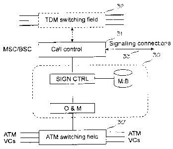
operates parallel with it. Figure 3 shows an MSC or a BSC according to the
invention. From a conventional MSC/BSC Figure 3 shows call control 3,
described only as a functional block representing all resources in general
that
can relate to call switching: call control, mobility management, radio
resources
management, etc. The call control 3 has signalling connections 33 (e.g. SS7)
to other network elements. The signalling connections can run entirely outside
the ATM layer. The signalling connections 33 are, however, preferably
permanent ATM virtual connections, through which PLMN signalling is
transparently transferred in a payload of ATM cells. As will be illustrated
with
examples given below, all PLMN signalling through the signalling connections
33 in the preferred embodiment of the invention is fully in accordance with
the
GSM recommendations.
The MSC/BTS in Figure 3 is further provided with an ATM switching
field (a matrix) 301 which the call control 3 controls through an interface
unit
30. The interface unit 30 in the embodiment of Figure 3 comprises the
following functional elements: a Management Information Base MIB, an ATM
signalling control SIGN.CTRL and an operational and maintenance interface
O&M to the switching matrix 301. The ATM signalling control SIGN.CTRL
ensures a UNI signalling according to references [ 1] and [2] and controls
switching operations of the switching matrix 301 through the O&M interface. In
the Management Information Base MIB are maintained status and
configuration information (management information) on virtual path and virtual
channel connections that are available for use at the UNI interfaces of the
ATM switch. Management information types available in the MIB are e.g. the
following: a physical layer; an ATM layer; ATM layer statistics; Virtual Path
Connections VPC; Virtual Channel Connections VCC; and address recording
information.
All interfaces between the ATM switching matrix 301 and the other
network elements (BTS, BSC, MSC, TC and/or the ATM network switch) are
user-to-network interfaces UNI. The UNI interface is defined in connection
with
references [ 1],[ 2] and [ 3]. For the ATM switching matrix, the PLMN network
CA 02283757 1999-09-13
WO 98/43456 - PCT/F198/00241
elements connected to it through the UNI interface thus represent
conventional ATM devices (users) or ATM switches which it can reach via the
UNI interface. PLMN network elements without an ATM switching function are
provided with an ATM interface device, which provides a UNI interface to the
5 ATM network 3 and a PLMN interface to the network element.
The MSC/BSC of the invention can comprise, in addition to the ATM
switching matrix 301, also a conventional TDM switching matrix 32, as shown
with a dashed line in Figure 3. This solution can be applied for instance when
other network elements are connected to the MSC/BSC, both with circuit-
10 switched connections and with ATM technology, and the MSC/BSC is to be
able to switch calls using both techniques. The MSC/BSC chooses the
switching technique to be used at a particular time according to whether the
other network element supports ATM technology or not.
Figures 4 to 6 illustrate different stages of evolution of the GSM
network architecture when ATM technology is applied. In Figure 4 ATM
technology is used on the transmission connections between exchanges
(using virtual trunking ATM). In other words, the transmission links 14 of
Figure
1 are replaced with ATM technology. In Figure 5 the circuit-switched
transmission links 11 and 12 (Figure 1) between the base station controller
BSC and the base stations BTS and the transcoder TC are replaced with
virtual ATM connections. The BSC is provided with an ATM switching function.
In Figure 6 all transmission links 11 to 14 (Figure 1) are replaced with
virtual
ATM connections. Figure 6 also describes best the method of approach
applied in the present invention. The base station controllers BCS and the
switching centres MSC (switching network elements in character) are provided
with an ATM switching feature so as to enable them to switch virtual ATM
connections between the base stations BTS and the transcoders TC and other
transmission type network elements. Figure 6 shows a data support 61 also as
a network element, said support usually denoting some kind of a router,
gateway or the like to a data network 62. The operation in question can be for
instance the connecting of a General Packet Radio System (GPRS) network to
a GSM network. An ATM transmission network 40, 50 or 60 in Figures 4 to 6
can be a normal ATM network comprising also actual ATM switches. The ATM
network 60 can also be connected to other ATM networks 2, such as B-ISDN,
or to other data networks 4, such as N-ISDN, PSDN (e.g. X.25) or the Internet.
CA 02283757 1999-09-13
WO 98/43456 PCT/F198/00241
11
An ATM network 40, 50 and 60 may advantageously be a standard
ATM network into which a wireless ATM concept has been created using a
network architecture and PLMN network elements provided with an ATM
switching capability of the invention. The architecture of a probable wireless
ATM network is of the type in Figure 6.
With a further reference to Figure 3, the call control 3 controls the
switching matrix by manipulating at the interface unit 30 the management
information related to the parameters of the ATM layers and the physical
layer.
The interface unit 30 performs the establishment, maintenance and releasing
of the virtual connections fully in accordance with UNI signalling.
In the following, an example of call switching will be described with
reference to Figure 7, said switching being performed using a
telecommunication network element of the invention provided with an ATM
switching function. The example is applicable to e.g. a network architecture
according to Figure 5, in which the BSC is a network element provided with an
ATM switching function. The example describes a handover (of a call)
between two BTSs which are switched to one and the same BSC that decides
when handover is to be performed (similarly -as in the GSM system). The
described mobile network signalling is in accordance with GSM signalling. It
is,
however, to be understood that the example is only intended to illustrate a
method of how a network element according to the invention is able to switch
virtual ATM connections between two points. The invention is not dependent
on the telecommunication system or network element in which, or on the type
of network signalling in connection with which the invention is to be applied.
As known from before, an MS measures, in addition to a serving
base station, downlink signals from a particular group of neighbouring base
stations. The MS regularly reports the measurement results to a base station
controller BSC which makes a decision on handover on the basis of the
results. Figure 7 shows an MS sending to the currently serving base station
BTS_o (referred to hereinafter as an old base station) the measurement report
in a measurement report message. The BTS_o transmits the measurement
report to the BSC in ATM cells through a permanent virtual connection PVC2.
Let us now assume that on the basis of the measurement results
sent by the MS (and according to the handover algorithm used ), the BSC
makes a decision that a call should be handed over from the old base station
BTS o to a new base station BTS n.
CA 02283757 1999-09-13
WO 98/43456 PCT/F198/00241
12
The BSC allocates the necessary radio resources to the connection
and commands the new base station BTS n to activate a traffic/radio channel
with a CHANNEL ACTIVATION message. In the preferred embodiment of the
invention, each radio channel of the base station BTS has a predetermined
address and a port in the ATM adjusting element of the base station and at the
UNI interface. The BTS n can thus switch the allocated traffic/radio channel
to
the correct ATM connection. Let us assume that the address of the
traffic/radio
channel thus allocated is addr 1, the predetermined VPINCI values related to
which the BTS_n acknowledges by sending a message CHANNEL ACTI-
VAT{ON_ACK.
The BSC sends to the old base station BTS o a
HANDOVER_COMMAND message, which comprises the information about
the new base station BTS_n: A handover according to the GSM
recommendations is then performed from the old base station to the new base
station. As a result of the handover, the radio interface traffic channel
allocated
for the call at the new base station BTS_n is switched to the logical
connection
established between the BSC and the new base station BTS n. The GSM
signalling related to the handover is not essential to the invention and will
not
therefore be described here in any detail. For a more detailed description of
the messages presented in Figure 7, reference is made to the above
mentioned book and to the GSM recommendations.
After the BSC has received from the new base station BTS n the
information (HANDOVER_COMPLETE) of the handover having been
completed on the radio path, the BSC switches the call from the virtual
connection of the old base station BTS o to the virtual connection of the new
base station BTS n and releases the virtual connection of the old base station
BTS_o. The related ATM signalling is illustrated in Figure 7 with blocks 70
and
80, shown with a dashed line. The signalling of blocks 70 and 80 is also
illustrated in Figures 8 and, correspondingly, in Figure 9, which also provide
an
example of the messages exchanged between the elements inside the BSC of
Figure 3. It is to be noted, however, that the internal function and structure
of
the BSC can be freely implemented and they are in no way restricted to the
examples shown in Figures 3, 8 and 9.
With reference to Figures 7 and 8, the call control 31 (Figure 3) of
the BSC issues the interface unit 30 a command to switch the traffic channel
as a virtual circuit between the base station BTS n and the BSC. To be
CA 02283757 1999-09-13
WO 98/43456 PCT/F198/00241
13
precise, the call control 31 sends a connect command to the signalling control
unit SIGN-CTRL. The connect command comprises as parameters the
addresses addr 1 of the new base station BTS n and addr 2 of the other
party (e.g. the TC). The addresses can be ATM or E.164 addresses. The
signalling control unit SIGN-CTRL then inquires of the MIP data base with a
command get_info the ports (of the ATM switching matrix 301) to which the
addresses addr 1 and addr 2 are connected to. The MIP provides in an info
response the port numbers and the VPINCI values that should be used for the
connections. The signalling control SIGN-CTRL then carries out a normal ATM
connection set-up procedure. In other words, the signalling unit SIGN-CTRL
sends to the new base station BTS_n a message ATM_UNI_Setup. The
BTS_n accepts the call by sending a message ATM_UNI_Connect. Since a
virtual connection to the other party already exists, it does not have to be
established again in this example. The signalling unit SIGN-CTRL commands
through the 0 & M interface (with a switch command) the switching matrix 301
to switch the VPINCI of the new base station BTS n to the VPINCI of the
other party. The SIGN-CTRL then issues to the call control 31 an
acknowledgement connect_ok.
With reference to Figures 7 and 9, the call control 31 of the BSC
issues to the interface unit 30 a command to release the virtual connection
between the old base station BTS_o and the BSC. To be precise, the call
control 31 sends a release command to the signalling control unit SIGN-CTRL.
The connect command comprises as parameters an address addr 3 of the
traffic/radio channel allocated at the old base station BTS_o. The signalling
control unit SIGN-CTRL then inquires of the MIP data base with a command
get_info the port (of the ATM switching matrix 301) to which the addr_3 is
connected to. The MIP provides in an info response the port number and the
VPINCI values used for the connection. The signalling control SIGN-CTRL
then carries out a normal ATM connection release procedure. In other words,
the signalling unit SIGN-CTRL sends to the old base station BTS_o a
message ATM_UNI_Release and the BTS_o acknowledges by sending a
message ATM_UNI_Release_Completed. The SIGN_CTRL issues to the ATM
switching matrix 301 a release command, which releases the virtual
connection of the old base station BTS o from the connection to the other
party. The SIGN-CTRL then issues to the call control 31 an acknowledgement
release_ok.
CA 02283757 1999-09-13
WO 98/43456 PCT/F198/00241
14
The BSC informs the MSC about the handover being performed
and then commands the old BTS_o to release the radio channel resources by
sending a GSM message RF_CHANNEL_RELEASE. The BTS_o sends an
acknowledgement message RF_CHANNEL_RELEASE ACK. The handover is
now completed.
When the MSC/BSC needs to set up virtual connections to both the
parties before the switching (e.g. in connection with call set-up), it sends
the
above described message ATM_UNI_Setup to both parties, who both respond
with the message ATM_UNI_Connect. The other party can be, in addition to a
PLMN network element, an ATM switch or an ATM terminal.
The attached drawings and the related description are only meant
to illustrate the present invention. The details of the invention can vary
within
the scope and spirit of the attached claims.