Language selection

Search

Patent 2283973 Summary

Third-party information liability

Some of the information on this Web page has been provided by external sources. The Government of Canada is not responsible for the accuracy, reliability or currency of the information supplied by external sources. Users wishing to rely upon this information should consult directly with the source of the information. Content provided by external sources is not subject to official languages, privacy and accessibility requirements.

Claims and Abstract availability

Any discrepancies in the text and image of the Claims and Abstract are due to differing posting times. Text of the Claims and Abstract are posted:

  • At the time the application is open to public inspection;
  • At the time of issue of the patent (grant).
(12) Patent: (11) CA 2283973
(54) English Title: THERMOSTATIC WATER MIXER
(54) French Title: MELANGEUR HYDRAULIQUE THERMOSTATIQUE
Status: Term Expired - Post Grant Beyond Limit
Bibliographic Data
(51) International Patent Classification (IPC):
  • G05D 23/13 (2006.01)
(72) Inventors :
  • KNAUSS, ERWIN (Germany)
(73) Owners :
  • HONEYWELL TECHNOLOGIES SARL
(71) Applicants :
  • HONEYWELL TECHNOLOGIES SARL (Switzerland)
(74) Agent: SMART & BIGGAR LP
(74) Associate agent:
(45) Issued: 2001-07-10
(86) PCT Filing Date: 1998-03-19
(87) Open to Public Inspection: 1998-10-01
Examination requested: 1999-11-26
Availability of licence: N/A
Dedicated to the Public: N/A
(25) Language of filing: English

Patent Cooperation Treaty (PCT): Yes
(86) PCT Filing Number: PCT/EP1998/001612
(87) International Publication Number: WO 1998043142
(85) National Entry: 1999-09-16

(30) Application Priority Data:
Application No. Country/Territory Date
197 11 760.0 (Germany) 1997-03-21

Abstracts

English Abstract


At a thermostatic water mixing valve the cold water fed to an inlet (12) and
the hot water
fed to an inlet (14) by means of valves (32, 34; 32', 34') is fed to a mixing
chamber (36),
whereat the valves are controlled by an expansion element (38). The expansion
element
(38) is arranged within a spring cage (40), the inner contour of which being
matched to the
outer contour of the expansion element (38). Furthermore, a ring gap (99) and
a collar (95)
are arranged in the mixing chamber in the zone where the cold water and the
hot water
come together. Soft sealing rings (32) inserted into the valve closing body
(28) give
protection against scalding when the cold water supply fails.


French Abstract

L'invention concerne un mélangeur hydraulique thermostatique dans lequel l'eau froide amenée à une admission (12) et l'eau chaude amenée à une autre admission (14) sont amenées dans une chambre de mélange (36) via des valves (32, 34, 32', 34') commandées par un élément de dilatation (38). L'élément de dilatation (38) est disposé dans une douille élastique (40) dont le contour interne est adapté au contour externe de l'élément de dilatation (38). Une fente annulaire (99) et un collet (95) sont en outre disposés à la confluence de l'eau froide et de l'eau chaude dans la chambre de mélange. Des anneaux d'étanchéité souples (32) insérés dans le clapet (28) protègent contre les risques d'échaudage en cas d'arrêt de l'alimentation en eau froide.

Claims

Note: Claims are shown in the official language in which they were submitted.

New Claims 1 to 5
1. Thermostatic water mixing valve, comprising:
a housing (10) having:
an inlet (12) for cold water;
an inlet (14) for hot water; and
an outlet for mixed water, where the inlet and the outlet all are connected to
a mixing
chamber (36);
a valve seat (34, 34'), each being arranged between the inlet for the cold
water and the
hot water and the mixing chamber;
a sleeve-shaped closing body (28) which is in driving connection with an
expansion
element (38), which is passed around by the mixed water, whereat the expansion
element comprises a bulge (42),
an adjusting element (76) for the displacement of the closing body (28)
together with
the expansion element (38) in order to provide a set value for the
temperature; and
an inner body (97) arranged within and concentric to the sleeve-shaped closing
body
(28) for forming a ring gap (99) for the water and a baffle face adjacent to
the outlet of
the ring gap (99) for promoting the mixing of cold water and hot water;
characterized in that:
a) the expansion element (38) is arranged within a spring cage (40), which is
tapered
over a portion of its longitudinal extension and which supports the expansion
element (38) by means of paraxial ribs (44) extending to the inner side;
b) the inner contour of the spring cage (40) is matched to the outer contour
of the
expansion element (38) and is essentially parallel to it;
c) the baffle face (96) is provided by the front face of the spring cage (40);
and
d) the spring cage (40) is guided within a sleeve (50) from synthetic resin,
whereat a
compression spring (48) is supported between the spring cage (40) and the
sleeve
(50) from synthetic resin.
2. Thermostatic water mixing valve according to claim 1, characterized
in that the upper rim of the sleeve from synthetic resin for limiting the
stroke of the closing body (28).

2
3. Thermostatic water mixing valve according to claim 2, characterized in
that the closing body is implemented as a sliding sleeve (28) which is
provided
with inserted soft sealings (32, 32') within the area of the seat.
4. Thermostatic water mixing valve according to claim 3, characterized in
that the expansion element (38) comprises a bulge (42) with an enlarged
diameter
at which the sleeve-shaped inner body (97) is abutting with an inwardly
extending
flange collar (94) and a nut (93) co-acting with an outer thread at the
expansion
element is clamping the flanged collar (94) between itself and the bulge (42).
5. Thermostatic water mixing valve according to one of claims 1 to 4,
characterized
by the operation as a distributing valve with the application of the
medium at the mixing water connection and by connecting the cold water
connection
and the hot water connection with a heat source.

Description

Note: Descriptions are shown in the official language in which they were submitted.


CA 02283973 2001-03-29
69660-26
1
The present invention relates to a thermostatic water
mixing valve.
Such thermostatic water mixing valves are known and
comprise commonly two valves controlled by a thermostatic
expansion element, which control entrance of cold water and hot
water into a mixing chamber, whereat the mixed water passes
around the thermostatic expansion element.
Known water mixing valves of this type show the
behaviour that an adjusted set value temperature is only
maintained in the event where the pressures on the inlet side
of the cold water and hot water are not subject to variations.
However, a control characteristic independent of the input
pressures is desired. To this respect an improvement is
provided by DE 44 23 240 C1 by providing a baffle plate within
the mixing zone. Departing from this prior art the present
invention aims at a still further improved control behaviour.
The present invention provides thermostatic water
mixing valve, comprising: a housing having: an inlet for cold
water; an inlet for hot water; and an outlet for mixed water,
where the inlet and the outlet all are connected to a mixing
chamber; a valve seat, each being arranged between the inlet
for the cold water and the hot water and the mixing chamber; a
sleeve-shaped closing body which is in driving connection with
an expansion element, which is passed around by the mixed
water, whereat the expansion element comprises a bulge, an
adjusting element for the displacement of the closing body
together with the expansion element in order to provide a set
value for the temperature; and an inner body arranged within
and concentric to the sleeve-shaped closing body for forming a
ring gap for the water and a baffle face adjacent to the outlet

CA 02283973 2001-03-29
69660-26
la
of the ring gap for promoting the mixing of cold water and hot
water; characterized in that: a) the expansion element is
arranged within a spring cage, which is tapered over a portion
of its longitudinal extension and which supports the expansion
element by means of paraxial ribs extending to the inner side;
b) the inner contour of the spring cage is matched to the outer
contour of the expansion element and is essentially parallel to
it; c) the baffle face is provided by the front face of the
spring cage; and d) the spring cage is guided within a sleeve
from synthetic resin, whereat a compression spring is supported
between the spring cage and the sleeve from synthetic resin.
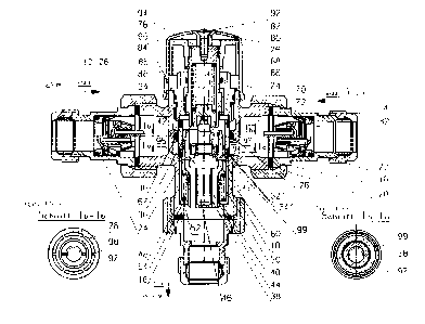
With respect to the sole figure of the attached
drawing in the following an exemplary embodiment of the
inventive thermostatic water mixing valve is described.
According to this sole figure, the thermostatic water mixing
valve comprises a housing 10 with an inlet 12 for cold water
and an inlet 14 for hot water. The mixed water emerges at an
outlet 16 being perpendicular to the inlets. Screw sockets 22,
within which back-flow preventers 24 are provided, are screwed
to the inlet and outlet by means of screw caps 20 with inserted
sealing rings 18. Within the symmetry plane of both inlets and
concentrically to a vertical symmetry axis a guiding ring 26 is
tip-stretched to the housing 10 within which a sleeve-shaped
closing body 28 sealed by an O-ring 30 is guided. The closing
body 28 comprises at both ends

CA 02283973 1999-09-16
2
sealing rings 32, 32' (soft sealings) which act together with seats 34, 34'
within the housing
10.' The valve formed by the sealing ring 32 and the valve seat 34 controls
the entrance of
cold water into a mixing chamber 36 and the valve formed by the sealing ring
32', and the
valve seat 34' controls the entrance of hot water into this mixing chamber 36.
The closing body 28 comprises in its inside a concentrically arranged sleeve-
shaped inner
body 97 made of synthetic resin, which at its upper portion by means of webs
98 (see
sectional view Ib-Ib) is connected to the closing body 28. In the lower
portion the webs 28
are missing so that a surrounding ring gap 99 (see sectional view Ia-Ia)
results. Since the
closing body 28, the webs 98 and the sleeve-shaped inner body 97 are formed in
one part
from synthetic resin, scale deposits are prevented, and the channeled cold
water is
prevented from influencing the thermostatic element.
Within the mixing chamber 36 a thermostatic expansion element 38 is provided.
The
expansion element 38 is seated in a spring cage 40, whereat it is supported by
means of a
bulge 42 with an enlarged diameter on paraxial ribs 44 extending from the
spring cage 40
to its inner side. Paraxial to the bulge 42 of the expansion element 38, the
spring cage 40
comprises a collar 95 which forms a baffle face 96 with its front. This baffle
face has the
effect that the cold water entering via the ring gap 99 is made turbulent with
the hot water
entering via the seat 34' and is guided closely along the expansion element
38. The inner
contour of the spring cage 40 is parallel to the outer contour of the
expansion element 38,
i.e. it is tapered within the transitional region from the bulge 42 to a
cylindrical portion 46
of the expansion element 38. Via a compression spring 48 the spring cage 40
abuts against
a collar 52 extending inwardly from a sleeve 50 made of synthetic resin which
is inserted
into the housing 10 from above and which abuts against a shoulder 54 extending
inwardly
from the housing 10. The upper rim of the sleeve 50 from synthetic resin
serves at the same
time for limiting the stroke of the closing body 28.
From above the sleeve-shaped inner body 97 with an inwardly extending flange
collar 94 is
inserted onto the bulge 42 of the expansion element 38. A nut 93 screwed onto
an outer
threading of the expansion element 38 is clamping the flange collar 94 between
itself and
the bulge 42.

CA 02283973 1999-09-16
The expansion element 38 abuts against a contact piece 64 with an upwardly
extending
plunger 62 with the contact piece abutting itself via a compression spring 66
in the recess
of a spindle 68. The contact piece 64 is secured within the recess of the
spindle 68 by
means of a snap ring 67. The spindle 68 is axially adjustable with an outer
thread engaging
an inner thread of a guiding sleeve 70, whereat the guiding sleeve 70 is
threaded into the
housing 10 and is sealed by means of O-rings 72 and 74 against the housing 10
and the
spindle 68.
A knurled knob 76 is screwed to the spindle 68 and is axially secured by means
of a
retaining ring 78. The set value temperature of the mixing valve is adjusted
by means of
the knurled knob 76. In order to prevent an unauthorized adjustment of the set
value
temperature, a cap 80 is provided which consists of transparent plastics and
which is put on
the knurled knob 76. The cap 80 surmounts the knurled knob 76, whereat it is
supported
with a central sleeve 82 on the spindle 68. The cap 80 comprises a paraxial
groove 84 at
the inner circumference at its jacket 86, which groove is overlapping a
paraxial rib 88 at
the housing 10. At the same time the rib 88 serves as a marking for the set
value
adjustment by means of the knurled knob 76, which bears an according dial. In
the area of
the groove 84 the jacket 86 is provided with an according projection 90
extending to the
outside. A countersunk screw 92 is gripping into an according recess in the
transition
region between the cap 80 and the sleeve 82 and is tightening the cap 80 with
the sleeve 82
against the spindle 68, when the countersunk screw 92 is screwed into an
according central
threaded hole 94 within the spindle 68. Naturally the cap 80 may be provided
with a rib
which is gripping into an according groove at the housing 10 in order to form
in this way a
protection against rotation of the cap.
The following operation of the described valve results from the above-
described design.
In the use as a mixing valve in hot water and heating installations the highly
sensitive
expansion element arranged within the mixing chamber or the outlet,
respectively, controls
the closing body 28, which as a function of the mixed water temperature, is
controlling the
entrance of cold or hot water, respectively. By means of the soft sealings
arranged at the
closing body a tight closure on the hot water side is effected in case of a
failure of the cold
water supply under the prerequisite that the hot water temperature is l OK
higher than the

CA 02283973 1999-09-16
4
mixed water temperature. On the other hand with the failure of a hot water
supply a
disvonnection of the cold water entrance is effected.
In the case where the thermostatic mixing valve is used as a distributing
valve for heating
installations, in particular with floor heatings in contrast to the mixing
valve, the valve is
flown through inversely, and the expansion element is controlling the closing
body in such
a way that with temperatures higher than the set value the water is flowing
back into the
heating installation and with temperatures lower than the set value the water
is directed to
the boiler.

Representative Drawing
A single figure which represents the drawing illustrating the invention.
Administrative Status

2024-08-01:As part of the Next Generation Patents (NGP) transition, the Canadian Patents Database (CPD) now contains a more detailed Event History, which replicates the Event Log of our new back-office solution.

Please note that "Inactive:" events refers to events no longer in use in our new back-office solution.

For a clearer understanding of the status of the application/patent presented on this page, the site Disclaimer , as well as the definitions for Patent , Event History , Maintenance Fee  and Payment History  should be consulted.

Event History

Description Date
Inactive: Expired (new Act pat) 2018-03-19
Letter Sent 2005-09-15
Inactive: Multiple transfers 2005-07-26
Grant by Issuance 2001-07-10
Inactive: Cover page published 2001-07-09
Inactive: Final fee received 2001-03-29
Pre-grant 2001-03-29
Inactive: Amendment after Allowance Fee Processed 2001-03-29
Amendment After Allowance (AAA) Received 2001-03-29
Notice of Allowance is Issued 2001-03-05
Letter Sent 2001-03-05
Notice of Allowance is Issued 2001-03-05
Inactive: Approved for allowance (AFA) 2001-01-31
Letter Sent 2000-05-01
Reinstatement Requirements Deemed Compliant for All Abandonment Reasons 2000-04-18
Deemed Abandoned - Failure to Respond to Maintenance Fee Notice 2000-03-20
Letter Sent 2000-01-13
Inactive: Single transfer 1999-12-16
Letter Sent 1999-12-13
All Requirements for Examination Determined Compliant 1999-11-26
Request for Examination Requirements Determined Compliant 1999-11-26
Request for Examination Received 1999-11-26
Inactive: Cover page published 1999-11-18
Inactive: First IPC assigned 1999-11-05
Inactive: Courtesy letter - Evidence 1999-10-26
Inactive: Notice - National entry - No RFE 1999-10-20
Application Received - PCT 1999-10-18
Application Published (Open to Public Inspection) 1998-10-01

Abandonment History

Abandonment Date Reason Reinstatement Date
2000-03-20

Maintenance Fee

The last payment was received on 2000-12-21

Note : If the full payment has not been received on or before the date indicated, a further fee may be required which may be one of the following

  • the reinstatement fee;
  • the late payment fee; or
  • additional fee to reverse deemed expiry.

Please refer to the CIPO Patent Fees web page to see all current fee amounts.

Owners on Record

Note: Records showing the ownership history in alphabetical order.

Current Owners on Record
HONEYWELL TECHNOLOGIES SARL
Past Owners on Record
ERWIN KNAUSS
Past Owners that do not appear in the "Owners on Record" listing will appear in other documentation within the application.
Documents

To view selected files, please enter reCAPTCHA code :


To view images, click a link in the Document Description column. To download the documents, select one or more checkboxes in the first column and then click the "Download Selected in PDF format (Zip Archive)" or the "Download Selected as Single PDF" button.

List of published and non-published patent-specific documents on the CPD .

If you have any difficulty accessing content, you can call the Client Service Centre at 1-866-997-1936 or send them an e-mail at CIPO Client Service Centre.


Document
Description 
Date
(yyyy-mm-dd) 
Number of pages   Size of Image (KB) 
Description 2001-03-29 5 225
Cover Page 2001-07-05 1 63
Abstract 2001-02-27 1 19
Representative drawing 2001-07-05 1 31
Representative drawing 1999-11-18 1 24
Abstract 1999-09-16 1 19
Description 1999-09-16 4 192
Claims 1999-09-16 2 72
Drawings 1999-09-16 1 58
Cover Page 1999-11-18 1 62
Acknowledgement of Request for Examination 1999-12-13 1 178
Reminder of maintenance fee due 1999-11-22 1 111
Notice of National Entry 1999-10-20 1 193
Courtesy - Certificate of registration (related document(s)) 2000-01-13 1 115
Courtesy - Abandonment Letter (Maintenance Fee) 2000-04-17 1 183
Notice of Reinstatement 2000-05-01 1 171
Commissioner's Notice - Application Found Allowable 2001-03-05 1 164
Correspondence 1999-10-20 1 14
PCT 1999-09-17 6 184
PCT 1999-09-16 15 605
Correspondence 2001-03-29 2 46
Correspondence 2001-03-29 5 225
Correspondence 2001-04-23 1 7