Note: Descriptions are shown in the official language in which they were submitted.
CA 02285349 1999-09-29
WO 98/46833 PCT/N098/00102
POSITION PENETRATED ANCHOR SYSTEM
The invention concerns a method for establishing and connecting and
disconnecting positioned anchorage points in different sea floor formations,
together with equipment for the same, arising from the need which exists
when anchoring floating units, independently of water depth.
When an object floating on the surface of the sea requires to be kept in
position for various reasons, an anchor is employed. This consists of a heavy
body, which is lowered on to the sea floor connected to a cable from the
floating object. By means of its shape the anchor offers the possibility of
becoming fixed to or exerting friction on the sea floor. For example, a ship
which loses engine power at sea will make use of a traditional and simple
anchor of this kind. In the same way this method of anchoring is employed
by ships which are lying in the roadstead, waiting to put in at a quay, etc.
The
positioning requirements for ships in such circumstances are minimal, and
the ship will normally be able to rotate freely 360° round the mooring
point,
according to the state of the current and wind direction.
Floating objects, such as drilling platforms, production ships and the like,
associated, e.g., with the oil and gas industry, have completely different and
more stringent requirements for their positioning with consequent
requirements for anchoring. This is due to the submerged pipe installations
which extend approximately linearly from the drilling floor vertically
through the water and on down deep to the oil and gas-bearing formations in
the earth's crust.
Present day technology masters positioning of this kind down to a depth of
approximately 700 metres, by the use of cable anchoring down and out from
the platform, the number normally varying from eight to sixteen catenaries
with attached plate anchors, or fluke anchors, at a cost of from NOK 1/2 mill.
to 2 mill. These catenaries, e.g., are generally approximately four to six
times
as long as the distance to the bottom, and are deployed radially with the
platform as the central point. In the outer end part of each chain there is
attached a fluke anchor, which is designed to dig into the sea bed for
securing co-operation with the sea floor when it is pulled over it towards the
CA 02285349 1999-09-29
WO 98/46833 PCT/N098/00102
2
platform by anchor-laying vessels and/or the floating unit's own established
tractive power.
Varying conditions on the sea floor and poor inspection capability reduce the
certainty of secure and permanent anchoring in times of severe stress, with
the result that unnecessarily stringent requirements are usually placed on the
number of anchor points. Due to their high price, amongst other things,
attempts must always be made to raise these fluke anchors for reuse.
Slack catenary mooring permits the platform, when exposed to wind and
current forces, to drift in the horizontal plane in any direction from the
central position to an extent corresponding to up to 5° from the
vertical
plane.
Another method of attachment to the se_a floor is a suction anchor. This is a
metallic, bell-shaped anchor body with the opening facing down towards the
sea floor. By means of a vehicle remotely operated from the surface of the
sea, a ROV (Remotely Operated Vehicle), the water is pumped out of the
body's internal volume, in order that the hydrostatic differential pressure at
such depths should cause the body to be pulled/pressed down into and
secured to the bottom. By this means a greater degree of controllable and
inspectable attachment is achieved, thus permitting a substantially tauter
mooring, with a shorter catenary.
Another remotely operated method of attachment at great depths is by
ramming down hollow tubes by means of hydraulic hammer power, which
tubes are thereby anchored in the bottom.
Securing by drilling in the bottom permits cylindrical hollow pipe anchors to
be lowered, where cement is filled in cavities around and inside the cylinder.
A catenary can then be attached to both the anchors' upper and top part
projecting up from the bottom, or it is made fast to the anchors' central part
projecting down into the bottom layer, in order thereby to exploit the
resistance forces which arise when a body is pulled towards and through a
surrounding mass.
Tension leg mooring is also employed, where anchors in the bottom with
vertical catenaries attached to the stays counteract the platform's buoyancy
by pulling it down in the water to an extent which has a stabilising effect.
CA 02285349 1999-09-29
WO 98/46833 PCT/N098/00102
3
Slack lines will occupy large areas in the sea and on the sea floor around a
platform. It is undesirable for such lines to cross a flow line and/or another
installation. Cables of metallic chain loops are heavy, also because each of
these cables normally represents four to six times the sea depth. For example,
S a platform at 300 metres deep employing 10 catenaries of 1$00 metres each
will altogether have deployed 1$000 running metres of chain. When the chain
weighs 160 kg/running metre, the total weight is 2,900 tons. If a theoretical
anchoring with the same means were performed at 3000 metres depth, the
catenary weight would amount to 29,000 tons.
At such depths other catenaries have to be employed. Steel cable, e.g.,
weighs approximately a third of the weight of chain, and yet 3000 m of the
dimension concerned weighs approximately 50 tons, forming an enormous
coil. Composite cable systems will also be bulky, but such cables submerged
in water are almost weightless.
A typical catenary can therefore be assembled by using large size steel cable
or chain in the lower end part with a plate anchor to weight it down; from the
floating unit steel cable or chain. The length between lower steel cable/chain
and upper steel cable/chain is composed of composite fibre rope, the splicing
being performed by means of special connecting units.
The method of the invention for establishing and connecting and
disconnecting positioned anchorage points in different sea floor formations is
primarily developed for operations at great depths with high hydrostatic
pressure, which makes it difficult if not impossible, also from the cost point
of view, to employ the present day known technology developed for
moderate depths, for transferring, amongst other things, prevailing forces,
catenary weights and dimensions, requirements for positioning, inspection,
etc.
Known technical equipment which is employed in such subsea operations is a
power-generating ROV (Remotely Operated Vehicle), which, at great depths
with the necessary capacity with a hydraulic pump, produces the torque,
tractive power and high liquid pressure for jetting and injecting effects.
A ROV is arranged to secured itself to the installation frame.
CA 02285349 1999-09-29
WO 98/46833 PCT/N098/00102
4
This is necessary to enable the ROV during turning work operations, such as -
screwing down wide-threaded cylindrical hollow threaded anchors or drilling
in the seabed, to counteract the torque or recoil forces from high-pressure
jetting and injecting to which it is exposed. The establishment of such power-
s generation on the installation frame is due to the fact that working at
great
depths complicates the operation supplying power from the surface.
From the patent literature the following publications are known:
- NO 803927 describes a submersible percussion hammer which is surface-
operated from a platform, which is supported by a truncated pyramidal frame
which projects upwards from sea floor level.
- NO 952476 describes a method for penetrating hollow cylindrical anchors
in the sea floor, where the anchors with connecting means are coupled to a
pillar of anchors stacked on top of one another, where the pillar's specific
weight helps to ram one anchor after another down into the bottom, where
these anchors are interconnected by lengths of chain which determine the
distance between the anchors' chain-forming positions.
- FR 2.444.755 describes a hollow helically flanked injector for anchoring
and reinforcement of loose masses, in that after being screwed down into
loose soil it permits a material which sets, e.g. liquid concrete, to be
injected.
The device is obviously surface-operated, and in itself does not represent an
anchoring function.
-SE 350.556 describes a percussion jetting device which is attached around
the lower end part of a pile, which during surface-operated ramming into the
ground with high-pressure water through obliquely downwardly jetting
nozzles, achieves an easier/faster penetration in loose earth masses and the
like.
- PCT/WO 95/20075 describes a bell-shaped suction anchor coupled to and
connected with one or more containers, where an underpressure has been
created by pumping out water at a great depth. By repeated sudden opening
and closing to the container's underpressure through the connection to the
suction anchor's interior cavity, the shock-like pressure changes are
transferred to the suction anchor, which penetrates the sea floor due to the
hydrostatic differential pressure. The device which contributes to lowering
CA 02285349 1999-09-29
WO 98/46833 PCT/N098/00102
the suction anchor here is the attached underpressure container(s). A standard
w
suction anchor consists only of the bell-shaped body, which with its opening
facing down on to the sea floor is first pumped empty of water, whereupon a
high hydrostatic differential pressure builds up at great depths. By suddenly
5 opening to this pressure, the suction anchor will be brought down into the
bottom masses.
- GB 2.148.968 describes a hollow cylindrical retrievable anchor, with
outwardly and downwardly foldable curved arms suspended attached at 90°
to the anchor body. The anchor's function is to create concrete foundations
under sea floor level, and then to be pulled up. The arms are folded into the
lower part of a cylindrical anchor body, also by the pressure from the
environment when being rammed down into the sea floor, but are folded out
by the anchor being pulled slightly up and back, the arms' outer parts being
turned inwards, thereby taking hold of the surrounding masses and on
account of the resistance therefrom being forced into an oscillating
movement from an enclosed position to a 90° extended position on the
anchor body. The ramming down operation is repeated by extending the
anchor body by joining on new hollow units, and the longitudinal cavity is
jetted with water. When the lower position has been reached, liquid concrete
is added through the cavity. Retrieval for repeated use of the anchor is
performed by lowering it further into the sea floor while jetting with water,
with the result that the surrounding masses press the arms in towards the
anchor body. The device may be described as an anchoring medium, and is
presumed to be surface-operated, for reinforcement of the ground's
supporting capacity, also because the force employed for the ramming down
operation is not described.
The method according to the invention is based on establishing anchorage
points which by means of recordable resistance force, permit a substantially
more vertical path in the water for the catenaries concerned, in order thereby
to reduce the length and weight of the catenaries, and to reduce the sea floor
area which is occupied during an installation of a ready-installed system.
This is also achieved by the fact that surrounding curved plate anchors
hinged in the anchor holder's upper or lower part will oscillate up and out or
CA 02285349 1999-09-29
WO 98/46833 PCT/N098/00102
6
down and out to a 90o- locked position on the anchor body when it is exposed -
to an upwardly or downwardly directed force.
At the same time the method requires and permits a high degree of accuracy
in positioning of the anchorage points.
To act as a ramming down ramp by securing and supporting the anchor
holders and controlling penetration thereof, a truncated pyramidal frame,
e.g., may be used consisting of one or more connected, e.g. inwardly sloping
or vertically located legs, which are connected to one or more suction
anchors, in order to become fixed to the bottom before an operation for
ramming down an anchor. To each of the upper ends of the frame legs there
are attached wirelines, which are used for lowering the frame from the
surface to the sea floor.
Centrally through the frame's vertical axis there is attached control and
suspension equipment for the insertion of the anchor holders concerned
possibly with a carrier for the respective operation.
Anchor holders for different anchors are mounted in a vertical position
through the frame's suspension equipment before lowering to the sea floor or
are inserted in the frame after it has been established on the sea floor.
The cylindrical or square anchor holders concerned are hollow or solid and
arranged for penetrating the sea floor, and by means of their design and
extension in the longitudinal direction adapted to different bottom
conditions.
An anchor holder which is jetted, injected, pressed/pushed or lowered into
established holes has simplified, flat plate attachments secured around both
cylindrical and square hollow anchor holders.
The common feature of the anchor holders with anchors concerned is that
when the floating unit is moved they have to be left in their bed on the sea
floor with a release mechanism which breaks the securing co-operation in the
shackle between the anchor and catenary. This takes place under sea floor
level if the anchor is left for good, and at sea floor level with a retrieval
marker if the anchor is to be used again.
Otherwise the method is in accordance with the characteristic features
according to claim 1.
CA 02285349 1999-09-29
WO 98/46833 PCT/N098/00102
7
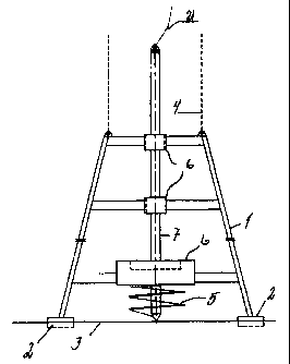
Fig. 1 illustrates a truncated pyramidal frame 1 consisting of four connected
inwardly sloping legs, which act as a ramming down ramp by securing and
supporting the anchor holders and controlling penetration thereof. A frame
with one or more vertically located legs is also a relevant design. The frame
is connected to one or more suction anchors 2 in order to become fixed to the
sea floor 3 before a ramming down operation. To the frame there are attached
wirelines 4 which are used for lowering the frame 1 from the surface to the
sea floor.
Fig. 2 illustrates schematically a helically flanked threaded anchor 5 with an
anchor cable 21 attached to the anchor holder 7 vertically disposed through
the frame's 1 suspension equipment 6. The illustrated flank width and pitch
exemplify the design of these anchors and are determined by the sea floor
mass's geotechnical data in order to obtain recordable and predictable
characteristics for resistance forces.
Fig. 3 illustrates schematically a release mechanism arranged through a
securing shackle for the catenary's attachment to the anchor with a tension
spring 13 and piston 14.
Fig. 4 illustrates a cylindrical solid anchor 15 with hinged attachment for
two
plate anchors 16 and 16' in the lower position vertically mounted in the
frame's 1 suspension equipment 6, where the plate anchor oscillates 90°
out
and up to a locked position on the anchor body when the anchor is exposed to
an upwardly directed force. This anchor is pressed/pushed down into the sea
bed 3 by hydraulic cylinders 17 with a sliding rim 18.
Fig. 5 illustrates a hollow metallic anchor holder 7 with a cylindrical or
square cross section for lowering to the bottom by jetting with water nozzles
19 and injecting suspended vertically in the frame's 1 suspension equipment
6, where flat plate anchors 20 coupled to the anchor Iine 21 accompanying
them during the lowering operation are set up, inside a square pipe also
diagonally for folding out at a 90° angle to a locked position on the
anchor
body.
Fig. 6 illustrates the anchor 15 with two plate anchors 16 and 16' for
penetration of the sea floor 3 mounted vertically in the frame's 1 suspension
equipment by means of a hydrostatic piston 22, which according to the prior
CA 02285349 1999-09-29
WO 98/46833 PCT/N098/00102
g
art is lowered in a closed cylindrical container 23 from the surface at 1 bar
pressure to, e.g., 1000 m at 100 bar, 5000 m at 500 bar etc., thus obtaining a
power release when opening a sealing packing on the underside of the
cylindrical container 23.