Note: Descriptions are shown in the official language in which they were submitted.
CA 02285630 1999-09-24
WO 98/42922 PCT/GB98/00899
-1-
UNDERWATER M~:INnVG MAC, IINE
BACKGROUND TO THE INVENTIION
THIS invention relates to an undetyvater mining machine of the typo used to
recover mineral bearing deposits from the sea bed or other underwater
location.
Underwater mining machines are adapted to gather material from the seabed
and transport the material to a processing vessel operating on the surface.
The mining machine is generally unmanned and will be controlled by an
operator situated on the vessel who is provided with control information
from sensors, on board cameras, and other information gathering devices
located on the mining machine.
Prior art machines are described in, for example, the specifications of South
African patent nos. 95/7262 and 92/6858.
In many underwater raining situations the material to be recovered from the
seabed is either covered by an overburden of hard or compacted material, or
is itself relatively homogenous and compacted and therefore needs to be
broken up before it can be transported to the surface. Diamond bearing
gravels, for example, are often covered by an overburden of sand and rock
which makes recovery of the gravels that much more problematic.
Prior art machines have not always had the capability of effectively or
efficiently dealing with a deep overburden or rock outcrop of any significant
size or hardness. Also, prior art machines in attempting to break up the
CA 02285630 1999-09-24
WO 98/42922 PCT/GB98/00899
-2-
overburden often leave an uneven track on which the machine must travel
causing problems with the forward movement of the machine and also
decreasing the efficiency of the gathering process.
SUMMARY OF T1~E NTYON
According to the invention an underwater mining machine includes:
a chassis mounted on a powered drive arrangement for driving the
chassis on an underwater surface, the chassis having a front end and
a rear end and being adapted to be manoeuvrable aad driven in at
least a forward direction;
a rotatable cutting drum secured to a boom which is attached to a
eradie mounted on the chassis; and
material gathering means adapted to gather material which has been
excavated or broken up by the cutting drum.
The cradle is preferably pivotally mounted on the chassis about a pivot axis
which may be inclined. The pivot axis may be inclined at an angle of
between S° and 45°, and preferably at an angle of about
25°. The pivot axis
of the cradle is preferably located in substantially the same vertical plane
as
the centre Line of the machine,
The cutting drum may be mounted transversely to the boom.
The cutting drum is preferably wider than the distance between the outer
edge of the tracks.
CA 02285630 1999-09-24
WO 98/42922 PCT/GB98/00899
_3_
The boom may be formed from at Least two elongate sections pivotally
connected together.
The machine may include a docking device for docking the machine to a
surface vessel.
The machine may also include processing means for grading material
lathered by the gathering means.
The material gathering means is preferably attached to the cradle.
According to another aspect of the invention an underwater mining machine
includes:
a chassis mounted on a powered drive arrangement for driving the
chassis on an underwater surface, the chassis having front end and a
rear end and being adapted to be manoeuvrable and driven in at least
a forward direction;
a rotatable cutting drum mounted at or adjacent to the front end of
the chassis and having an axis of rotation which is generally
horizontal and perpendicular to said forward direction; and
material gathering means adapted to gather material which has been
excavated or broken up by the cutting drum.
These and further features of the invention will be made apparent from the
description of a preferred ernbodiraeat thereof given below by way of
example. In the description references match the accompanying drawings
CA 02285630 1999-09-24
WO 98/42922 PCT/GB98/00899
-4-
but the specific features shown in the drawings should not be construed as
limiting on the invention.
BRIEF DESCRIPTION OF TSE DRAWINGS
Figure 1 shows a side view of an underwater mining machine
according to the invention;
Figure 2 shows a plan vicw of the machine shown in Figure 1 (with
the boom and cutter drum removed for clarity);
Figure 3: shows a sectional view along lines C-C depicted in Figure 1.
Figure 4 shows a part longitudinal section along the center line of the
machine; and
Figure S shows a section along section line A-A depicted in Figurc 4.
DETAILED DESCRIPTION OF THE PREF>FxRRED EMBODIMENT
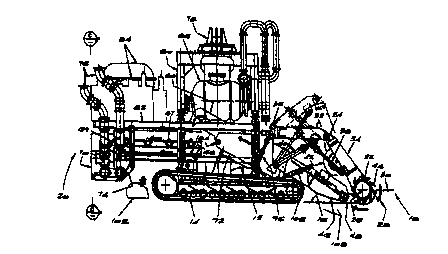
As shown in the drawings, an underwater mini.ag machine 10 comprises a
chassis 12 whicl~.is mounted on tracks 14 and is adapted to be driven on an
underwater surface 16, The vehicle 10 has a front end I8 and a tear end 20.
A rotatable cutting drum 22 is mounted via a boom 24 to the chassis I2.
The drum 22 is rotatable on an axis 26 in the direction of arrow 28 in order
to cut a swath of material 30 as the machine moves in a forward direction.
CA 02285630 1999-09-24
WO 98/42922 PCT/GB98/00899
-5-
The boom 24 is formed in two sections numbered 32 and 34. The section
34 has the cutting drum 22 mounted oa the free end thereof, and section 32
is pivotally connected by a pivot assembly 36 to the chassis via a cradle 92.
The two sections 32 and 34 are connected together by a hydraulic piston
cylinder assembly 38 which is used to vary the angle between the two
actions. The boom is raixd and lowered by a hydraulic piston and cylinder
assembly 40 and the two piston and cylinder assemblies 38 and 40 are used
to position the cutting drum 22 in either a retracted, noa-operative position
(as indicated by dotted lines 42) or in a position forward therefrom in which
the cutting drum is the leading component on the machine.
The cutting drum 22 has a multiplicity of cutting teeth 44 mounted thereon
which are angled as shown to optimally cut the material 30 to be excavated
by the machine. The cutting teeth 44 are located in a scroll configuration
to draw material towards the centre of the drum.
The cutting drum has a width which is wider than the distance between the
outer edges of the tracks 14. Thus, the cutting drum will cut a swath
through the material 30 which forms a roadway in which the machine can
travel. Since the axis of rotation of the cutting drum is generally horizontal
that roadway will be basically horizontal cad will define a relatively smooth
path for the forward travel of the machine.
Material that has been cut or broken up by the cutting drum 22 will be
gathered onto the machine by means of a spade assembly 46. The spade
asscrnbly 46 has a sharpened leading end 48 which leads to a generally
planar apmn 50 best seen in Figure 2 of the drawings.
CA 02285630 1999-09-24
WO 98/42922 PCT/GB98/00899
-6-
A pair of material directing wheels 52 are mounted on the spade and have
an axis of rotation which is perpendicular to the plane of the apron 50. The
wheels 52 are of star shaped configuration and each has three gathering arnns
54 thereon which are adapted to guide or move material on the apron 50
towards the centre thereof. The wheels rotate in the direction of arrows 58
so that material anywhere on the apron 50 is directed to the centre of the
apron.
A conveyor device 60 is used to transport the gathered material up and back
towards the centre of the vehicle for initial processing. The conveyor 60 is
of an ox-chain type conveyor comprising a multiplicity of slats 64 which
span between chains 66, the chains being driven in a circular path.
The material from the conveyor 60 is deposited on a screen assembly 67
which is designed to allow smaller particles and fine material to pass through
the screen onto a lower conveying assembly 68. Coarser particles are moved
along the length of the screen assembly 67 to pass off the rear end of the
machine as indicated by arrow 69 through a chute 70. The finer materials
are conveyed along the conveyor assembly 68 to a hopper 74 sad from there
it is transported to the surface by an air lift assembly 76. Air Iift
assemblies
are well known and need not be described herein in any greater detail. The
screen will ~e fitted with an away of high pressure water jets to assist with
clay dissaglomcratioa.
The machine is provided with a docking device 78 which is attached to the
cha55iS by aliilS 80.
The machine is also provided with a platform 82 on which hydraulic power
packs 84 and dectrical sad electronic storage containers 86 arc mounted.
CA 02285630 1999-09-24
WO 98/42922 PCT/GB98/00899
' Turning now to Figures 4 and 5 of the drawings, the means by which the
boom 24 is mounted to the c~hsssis is described in more detail. As shown,
the section 32 of the boom 24 comprises a pair of arms 90 which are spaced
apart by a width greater than the width of the conveyor 60 so that the
conveyor 60 travels therebetween. The arms 90 arc able to pivot about pivot
points 36 as described above. The pivot points 36 arc located on the cradle
92 which itself is pivotably connected to the chassis and is able to pivot
about pivot axis 94 which is located along the approximate centre line of the
vehicle. The pivot axis 94 is inclined of an ankle of approximately 25°
to
the horizontal. The cradle may have multiple degrees of freedom. In one
form of the invention the cradle has two degrees of frxdom.
The conveyor 60, the spade assembly 46, and the boom 24 are all mounted
on the cradle 92 so that pivoting of the cradle 92 about its pivot axis 94
pivots the boom (and hence the cutting drum), the spade 46 and the
conveyor 60. This allows the cutting and material gathering components of
the machine to be angled relative to the surface 16 on which the tracks 14
are travelling. This can be advantageous in certain excavating situations.
The angle of the cradle 92 relative to the chassis is controlled by a pair of
piston and cylinder assemblies 96. It is envisaged that the cradle 92 will be
able to pivot through an arc of approximately 12°. Clearly, an arc of
greater
than this (up to 20°) will be possible althoush it is envisaged that an
arc of
12° should be sufficient for the purposes described. The chassis is
provided
with mounting brackets 98 within which pivot assemblies 100 arc located.
The spade 46 and conveyor 60 are pivotally connected to the esadle 92 via
a pivot point 104. The pivot point 104 has a pivot axis which is generally
perpendicular to the length of the conveyor 60. The conveyor b0 and spade
CA 02285630 1999-09-24
WO 98/42922 PCT/GB98/00899
_g_
46 can be moved so as to pivot about pivot point 104 by means of a pair of
hydraulic piston and cylinder assemblies 106, This allows the leading edge
of the spade to be lowered (as indicated at dotted lines 108), or raised, and
it is envisaged that the length of travel between its fully down and fully up
position will be approximately 600mm. Gcaerahy, however, the leading
edge of the spade will be nominally at the same elevation as the surface i 6.
However, for inclined terrain or undulating.terrain the ability of the spade
to move above the nominal level of the tracks or below the nominal level of
the tracks will be advantageous and will improve the efficiency of the
recovery process.
The preferred arrangement is for the cutting drum and the spade to be
approximately 3.9 m wide. The distance between the outer edges of the
tracks will preferably be approximately 3,36m. Thus, there will be a gap
between the edge of the excavation and the outer edge of the track on each
side of the machine in normal operating conditions. The spade should gather
all material from the track so that the path being travelled on by the tracks
is relatively smooch. The platform may be wider than the width of the
excavated track since it is located above the track and therefore will not
come into contact with the surface over which the machine is travelling.
It is will envisaged that the machine will be able to process material at the
rate of approximately 530 tons per hour. The maximum speed of the
machine in a forward or reverse direction will be approximately 15 m per
minute.
The drum should be rotatable at a rotational speed of between 20 and 70
rpm and it is envisaged being powered by 2 x 120 kW hydraulic motors.
CA 02285630 1999-09-24
WO 98/42922 PCT/GB98/00899
-9-
The material directing wheels will be rotatable at speeds of betwcea 0 and
s 25 rpm and each will be powered by 45kW hydraulic motors. The spade
will be adjustable in height by 300mm above and below the normal track
height. The spade will also be able to move laterally by approximately 150
mm each side of the longitudinal centre lice of the vehicle.
The conveyor 60 will operate at between 0,25 and 1,5 m per second and will
be powered by a 37kW hydraulic motor. The scrxn conveyor 68 will
operate in a speed range of 0,25 to 2,0 m per second and will be powered
by a 25 kW hydraulic motor. The tracks 14 will each be powered by 2 x
SO kW hydraulic motors and the screen 67 will be operated by 3 x 7,5 kW
hydraulic motors and have a screen capacity of 700 tons per hour. The
screen 67 will have a screen eui point size of -100mm.
With different operating conditions the following porfor~aance and speed of
operation are envisaged:
Cycle 1: (Material centre depth 1,2)
Face Area = 1,2 x 3,0 - 3,6m2
Forward speed - ~(m3/f~ = 69m/h
3,6
Time to complete 1 lane = 100 - 87mins
69
Lift spade and prepare to reverse - 2mins
Reverse 120 meters = 120 = lOmins
' 12
Align m/c and cut to depth - lOmins
Total cycle time -. 80rnins
No of cycles I20hr day = 20 x"60 - 15
CA 02285630 1999-09-24
WO 98/42922 PCT/GB98/00899
- 10-
Area/cycle - 30 x 100 = 300m2
at 1,2 depth Area/day - 3300m~
cle (Material depth 0,8)
Face Area - 0,8 x 3,0 s 2.4m2
Forward speed - 250(m3/I-~ = 104m/h
2,4
Time to complete 1 lane 100 - 58mins
-
104
Lift spade and prepare to - 2mins
reverse
Reverse 120 meters - lOmins
Align m/c and cut to depth = lOmins
Total cycle time = 80mins
No of cycles /2ohr day - 20 x 60 - 15
80
Area/cycle - 30 x 100 - 300m~
at 0,8 depth Area/day = 4500mz
Cycle 3: (Material centre depth 0,5)
Face Area - 0,5 x 3,0 ~ l,Sm2
Forward speed - 250(m'/I~ = 167m/h
1,5
Time to complete 1 lane ~ 100 ~ 36mins
167
Lift spade and prepare to reverse = 2mias
Reverse 120 meters - l Omins
Align m/c and cut to depth = lOmins
CA 02285630 1999-09-24
WO 98/42922 PCT/GB98/00899
- 11 -
Total cycle time . = Sgn~in5
No of cycles /20hr day - 0 x 60 - 20 7
58
Area/cycle = 30 x 100 - 300m~
at 0, 5 depth Area/day - 621 Omz
C c a 4: (Material centre depth 0,3)
Face Area - 0,3 x 3,0 -
Forward speed ; 250(m3/~ - Z~g~
0,9
Time to complete I lane = ~0 = 22nzias
z~s
Lifr spade and prepare to reverse - 2mins
Reverse 120 meters - lOmins
Align m/c and cut to depth - lOmins
Total cycle time - 4.4mins
No of cycles /20hr day - 2~ - 27,3
44
Area/cycle - 30 x 100 - 300m=
at 0,3 depth Arealday = 8182m=
It is envisaged that a machine of the aforementioned type will operate at
depths up to 200m below sea level. The machine will also carry on board
performance monitoring sensors and transducers and will carry standard on
board cameras and other guidance aids for the operator. Generally it is
envisaged that the machine will cut a lane or swath 3,9m wide and that the
lane will run for 100m. At the end of the 100m travel, the machine will
CA 02285630 1999-09-24
WO 98/42922 PCT/GB98/00899
- 12-
reverse back to the start of the lane and will then commencing cutting a new
Lane adjacent the previous lane.
'The machine will carry a suction head located behind the tracks of the
vehicle (as indicated at numeral 102) which will suck up any fine material
which has not been gathered onto the spade.
Control of the spade in the X,Y & Z plane may be achieved via a sediment
depth measurement system.
There may be many variations to the above described embodiment without
departing from the scope of the invention. However, it is envisaged that a
cutting head of the type described herein should prove advantageous over
prior art systems which should result in improved recovery of valuable
minerals from the seabed or other underwater location where the machine is
operated.