Note: Descriptions are shown in the official language in which they were submitted.
CA 02285637 1999-09-24
.
.
v . . . . ~.TT - . . 7
t
- 1
INHALATION DEVICE
This invention relates to an inhalation device
for use in enabling material in aerosol form to be
dispensed from a container and inhaled by a user.
Inhalers are well-known in medicine for the
treatment or alleviation of the symptoms of
respiratory complaints such as asthma. One type of
conventional inhaler comprises a housing which
receives a container of medicament and a spacer member
into which the medicament is dispensed and from which
it is inhaled by the user through a mouthpiece
opening. The medicament enters the spacer member via
a nozzle so that it is dispersed into a fine spray
before being inhaled. Such a device has an
inoperative condition in which the housing enclosing
the container is received within the spacer member and
an operative condition in which the housing is
withdrawn from the spacer member and is pivoted so as
to be positioned at an angle to it, typically in the
region of 90°. Examples of such devices are described
in W092/20391-A1, EP 0 009 667 and U.S. 3,994,421.
Existing spacer inhalers of this type are
relatively complex constructions. For example, in
order to achieve the range of movement between the
operative and inoperative positions, conventional
inhalers comprise an extra part known as the saddle
which is slidably received within the spacer member
and to which the housing is pivotally attached.
The present invention aims to provide a
simplified design which is easier and cheaper to
produce whilst providing improved operation.
aMEMDzD SHE~~
CA 02285637 1999-09-24
WO 98/42395 PCT/GB98/008Z7
- 2 -
In one aspect of the present invention there is
provided an inhalation device for use with an aerosol
container, the device comprising a housing for
receiving an aerosol container and a spacer member
defining an outlet through which a user can inhale,
the housing and the spacer member being attached
together so as to be movable with respect to each
other between an inoperative position in which the
housing is received within the spacer member and an
operative position in which the housing is withdrawn
from the spacer member and oriented at a substantial
angle thereto, the device further comprising a
dispensing member for receiving material to be
dispensed from said aerosol container and delivering
said material into the spacer member, wherein the
dispensing member is located in said housing and is
supported spaced from the walls thereof by a plurality
of spaced ribs.
This configuration provides improved support for
the dispensing member whilst allowing air flow through
the housing and into the spacer member, which improves
operation as the user inhales. Manufacture of the
housing is also simplified.
Preferably, the ribs which support the dispensing
member are not equally spaced.
In a preferred embodiment, four ribs are present
which may be arranged symmetrically in two pairs.
In a second aspect of the present invention there
is provided an inhalation device for use with an
aerosol container, the device comprising a housing for
receiving an aerosol container and a spacer member
CA 02285637 1999-09-24
WO 98/42395 PCT/GB98/00827
- 3 -
defining an outlet through which a user can inhale,
the housing and spacer member being attached together
so as to be movable with respect to each other between
an inoperative position which the housing is received
within the spacer member and an operative position in
which the housing is withdrawn from the spacer member
and oriented at a substantial angle thereto, the
device further comprising a dispensing member for
receiving material to be dispensed from said aerosol
container and delivering it into said spacer member,
wherein said spacer member further comprises a
forwardly extending mouth piece member defining the
outlet and the housing further comprises a forwardly
extending projection, shaped so as to be received by
said mouthpiece member in the inoperative position in
order to close the outlet.
In this way, a separate cap member as used in
conventional spacer inhalers to close the outlet in
2a the inoperative position is not required.
Conveniently, the forwardly extending projection
and the spacer member are adapted to co-operate with
one another in the operative condition in order to
retain the housing at a predetermined angle relative
to the spacer member.
Preferably, this is achieved by providing the
projection and the spacer member with co-operating
3o surfaces which are brought into frictional engagement
as the device is moved from the inoperative to the
operative condition.
The invention will now be described in detail, by
way of example only, with reference to the
CA 02285637 1999-09-24
WO 98/42395 PCT/GB98/00827
- 4 -
accompanying drawings in which:
FIGURE 1 is a perspective exploded view of a
first embodiment of an inhalation device in accordance
with the present invention;
FIGURE 2 is a perspective view of the inhalation
device of Figure 1 in the inoperative position;
FIGURE 3 is an enlarged view of the proximal end
of the body portion of the device of Figure 1;
FIGURE 4 is a sectional view of the inhalation
device of Figure 1 in the inoperative position;
FIGURE 5 is a sectional view of the inhalation
device in the operative position;
FIGURE 6 is a perspective view of the housing of
an inhalation device in accordance with a second
embodiment of the present invention;
FIGURE 7 is a perspective view of a spacer member
of an inhalation device in accordance with the second
embodiment of the invention; and
FIGURE 8 is a sectional view of the housing and
spacer member of Figures 6 and 7 connected together in
the operative position.
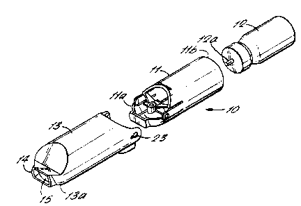
An inhalation device 10 in accordance with a
first embodiment of the present invention is
illustrated in Figures 1 to 5. It comprises a
substantially tubular housing 11 which is elliptical
in cross-section and which is open at its distal end
llb for receiving a conventional container 12 of
medicament.
The housing 11 is pivotally connected at its
proximal end lia to a substantially tubular spacer
member 13 which also has an elliptical cross-section
which is larger than that of the housing 11. At its
proximal end 13a, the spacer member 13 is formed with
CA 02285637 1999-09-24
WO 98/42395 PCT/GB98/00827
- 5 -
a mouthpiece member 14 which defines an outlet 15
through which a user may inhale medicament dispensed
from the container 12.
The housing 11 and spacer member 13 are
preferably made from moulded plastics material.
The inhalation device 10 can be moved between an
inoperative position illustrated in Figures 2 and 4
and an operative position illustrated in Pigure 5. In
the inoperative position, the housing 11 is received
within the spacer member 13. In the operative
position, the housing 11 is withdrawn from the spacer
member 13, pivoted through a substantial angle, e.g in
the range of 90° to 105°, and locked in that position.
In order to lock the housing 11 and spacer member
13 in the operative position, the housing is provided
with a slot or recess 26 adjacent its proximal edge
which is engaged by a locking tab 27 projecting
distally from the adjacent edge of the spacer member
13.
The aerosol container 12 received in the housing
11 is provided with a conventional dispensing head 12a
which is received by a dispensing member located in
the proximal end of the housing 11. The dispensing
member comprises a nozzle block 16 which defines a
passage 17 which receives medicament dispensed from
the container 12. The passage 17 communicates with a
nozzle 18 also defined by the nozzle block 16 but
which has its axis at a substantial angle, for example
in the range of 90° to 105°, to that of the passage 17.
In the operative position of the device 10 as
CA 02285637 1999-09-24
WO 98/42395 PCT/GB98/00827
- 6 -
shown in figure 5, the nozzle 18 is axially aligned
with the spacer member 13. When the end of the
container 12 is depressed by a user through the open
distal end llb of the hausing 11, medicament is
dispensed into the passage 17 and transmitted via the
nozzle 18 as a fine spray into the spacer member 13
from which it is inhaled by the user through the
outlet 15.
In conventional inhalers, the nozzle block is
suspended from the wall of the housing by means of a
single stem portion. Alternatively, it may be formed
with a solid annular web which completely surrounds it
and extends to the walls of the housing. In the
present invention, the nozzle block 16 is supported on
a plurality, and preferably four, spaced ribs 19 as
seen in Figure 3. The four ribs 19 provide more
stable support for the nozzle block 16 than a single
support stem and the gaps between the ribs 19 allow
for air flow through the body portion and into the
spacer member which leads to improved operation of the
device 10. Furthermore, the four rib configuration
eliminates sink marks and voids which tend to be
created in conventional inhalers which use a single
stem to support the nozzle block. These faults can
distort the nozzle block and the nozzle aim. During
production, the four rib configuration also makes for
a simpler and more efficient mould cavity.
As shown, the four ribs 19 are preferably not
equally spaced but are positioned symmetrically in two
opposed pairs such that each rib joins the housing
wall adjacent one of the cantilever arms 20 which are
described further below.
CA 02285637 1999-09-24
WO 98/42395 PCT/GB98/00827
At its proximal end lla, the housing 11 is formed
integrally with two cantilever arms 20 which are
diametrically opposed to one another. Each arm 20 has
an outwardly projecting trunnion 21 formed at its free
end.
At the distal end of the spacer member 13, there
are formed a pair of diametrically opposed ears 22
which extend rearwardly, each having a keyhole
aperture 23 therethrough.
In the inoperative position of the device 10,
when the housing 11 is received within the spacer
member 13, the cantilever arms 20 are forced to flex
slightly inwardly and the trunnions 21 are slidable
against opposite sides of the elliptical interior
surface of the spacer member 13. As the housing 11 is
withdrawn from the spacer member 13 the trunnions 21
slide along the walls until the cantilever arms 20 are
able to relax outwardly so that the trunnions 21
engage in the keyhole apertures 23. The housing 11
may now be pivoted relative to the spacer member about
an axis defined by the trunnions 21 and perpendicular
to the longitudinal axis of the housing 11 and the
spacer member 13.
In order to return the device to the inoperative
condition the cantilever arms 20 are flexed inwardly
sufficiently to disengage the trunnions 21 from the
apertures 23. The housing 11 can now be slid once
more into the spacer member 13 with the trunnions 21
sliding along the side walls.
Thus, all the components of the pivot arrangement
are formed integrally with either the housing or the
CA 02285637 1999-09-24
WO 98/42395 PCT/GB98100827
_ g _
spacer member, reducing the complexity and hence the
cost of the inhaler. Actuation of the device to move
between the operative and inoperative positions is
also simplified.
As mentioned above, the spacer member 13 is
provided with an outlet 15 through which a user
inhales the medicament.
As best seen in Figure 3, the proximal end lla of
the housing 11 is formed with an extension piece 24
which extends through less than half of the
circumference of the housing 11 and which projects
proximally of the cantilever arms 20. The extension
piece 24 is shaped so as to fit snugly into the outlet
15 defined by the mouthpiece member 14 so that in the
inoperative condition, the extension piece 24 acts as
a closure member for the outlet 15 to prevent the
ingress of dirt or other contaminants.
Thus, the device is integrally formed with a
closure member and there is no need for a separate cap
or cover as in the prior art which could be lost or
even inhaled by a user who had inadvertently left the
cap an the inhaler. The number of parts to be
produced is also reduced, lowering cost and
simplifying manufacture of the device.
A second embodiment of inhalation device in
accordance with the present invention will now be
described with reference to Figures 6 to 8. Many
aspects of the second embodiment are the same as those
in the first embodiment and thus like reference
numerals have been used in the drawings to indicate
like parts.
CA 02285637 1999-09-24
WO 98/42395 PCT/GB98/00827
- 9 -
The inhalation device 40 in accordance with the
second embodiment once again comprises a tubular
housing 11 of elliptical cross-section for receiving a
' container of medicament and being pivotally connected
to a spacer member 13 of larger elliptical cross-
section.
An approximately semi-circular cut-out 41 is
provided on each side of the distal end ilb of the
housing 11 to enable a user to depress the container
of medicament 12 which is within the housing in order
to dispense the medicament or to enable the user to
grasp the container to withdraw it from the housing 11
when it needs to be replaced.
In addition, at the distal end of the housing 11
there is a small thumb tab 42 which is provided to
help the user to withdraw the housing 11 from the
spacer member 13.
In the second embodiment, the retaining mechanism
which holds the housing 11 and spacer member 13 in the
operative position comprises a plurality of inwardly
extending feet 43 formed at the distal end 13b of the
spacer 13 as shown in Figure 7. A plurality of
corresponding outwardly extending feet 44 are formed
on the end face 45 of the extension piece 24 provided
at the proximal end of the housing 11. When the
housing 11 is rotated relative to the spacer member
13, the projecting feet 43 and 44 are brought into
frictional engagement with each other so as to retain
the housing and the spacer member in the operative
position by interference with one another.
Preferably, the projecting feet 44 formed on the
housing 11 have a curved profile and two or more may
CA 02285637 1999-09-24
WO 98/42395 PCT/GB98/00827
- 10 -
be provided with a stepped portion 46. As the housing
11 is rotated towards the operative position, the
projecting feet 43 and 44 are gradually brought into
closer frictional engagement and eventually snap over
the stepped portion 46 into the final operative
position.
In the second embodiment, in order to provide
pivotal engagement between the housing 11 and the
spacer member 13, the spacer member 13 is provided
with a pair of opposed inwardly projecting trunnions
~7 at its distal end 13b (only one of which is visible
in Figure 7). A pair of opposed axially extending
slots 48 are formed in the outer surface of the
housing 11 to receive the trunnions 47. Thus, in the
inoperative position, the housing 11 is located within
the spacer member 13 in the same manner as in the
first embodiment.
To reach the operative position, the housing 11
is withdrawn from the spacer member 13 with each
trunnion 47 running in a respective slot 48. In the
fully retracted position, the trunnions 47 are located
at the blind end of each slot 48 at the proximal end
lla of the housing 11 and the housing 11 may then be
pivoted with respect to the spacer member 13 about an
axis defined by the trunnions 47.
Finally, in Figure 8 it can be seen that the
inner surface of the housing 11 is provided with a
number of inwardly projecting ribs 49 which serve to
locate the medicament container 12 centrally within
the housing 11 so that the dispensing member 12a will
easily locate into the nozzle block 16. It will be
apparent that such ribs together with other features
CA 02285637 1999-09-24
WO 98/42395 PCT/GB98/00827
- 11 -
such as the cutouts 41, thumb tab 42 and inter-
engaging feet 43 and 44 although described with
reference to the second embodiment are equally
applicable to the first embodiment in addition to or
instead of the corresponding features of the first
embodiment.
From the foregoing it will be apparent that the
present invention provides an improved inhalation
device with fewer parts which is easier to make and
assemble and which provides improved operation in use.