Note: Descriptions are shown in the official language in which they were submitted.
CA 02286241 1999-10-06
WO 98/50486 PCT/US98/08686
HYDROCARBON SYNTHESIS CATALYST SLURRY
REJWENATION WITH GAS DISENGAGEMENT
BACKGROUND OF THE DISCLOSURE
Field of the Invention
The invention relates to a process and apparatus for in-situ rejuvenating
solid
catalyst particles suspended in a slurry. More particularly, the invention
relates to a
process and means for rejuvenating solid catalyst particles dispersed in a
three phase,
Fischer-Tropsch type hydrocarbon slurry comprising said particles, a
hydrocarbon iiquid
phase and gas bubbles in-situ in the slurry, in which gas bubbles are removed
from the
slurry entering the rejuvenation zone.
Background of the Invention
Slurry hydrocarbon synthesis (HCS) processes are known. In a slurry HCS
process a synthesis gas (syngas) comprising a mixture of H2 and CO is bubbled
up as a
third phase through a slurry in a reactor in which the slurry liquid comprises
hydrocarbon products of the synthesis reaction and the dispersed, suspended
solids
comprise a suitable Fischer-Tropsch type hydrocarbon synthesis catalyst.
Reactors
which contain such a three phase slurry are sometimes referred to as "bubble
columns",
as is disclosed in U.S. Patent 5,348,982. Irrespective of whether the slurry
reactor is
operated as a dispersed or slumped bed, the mixing conditions in the slurry
will typically
be somewhere between the two theoretical conditions of plug flow and back
mixed.
Syngas made from hydrocarbon feedstocks which contain nitrogen (i.e., natural
gas) or
nitrogen containing compounds (i.e., resids, coal, shale, coke, tar sands,
etc.) invariably
contains HCN and NH3 which contaminate the reactive slurry and rapidly, but
reversibly, deactivate the cataiyst. Certain oxygenates and carbonaceous
compounds
CA 02286241 1999-10-06
WO 98/50486 PCT/ITS98/08686
-2-
formed in the slurry as by-products of the HCS reaction can also cause rapid
deactivation. Deactivation of such catalysts by these species is reversible
and catalytic
activity is restored (the catalyst rejuvenated) by contacting the deactivated
catalyst with
hydrogen. The activity of the HCS catalyst in the reactive slurry may be
intermittently
or continuously rejuvenated by contacting the slurry with hydrogen or a
hydrogen
containing gas to form a rejuvenated catalyst slurry as is disclosed, for
example, in U.S.
Patents 5,260,239 and 5,268,344. In these patents the slurry, containing gas
bubbles, is
rejuvenated by circulating it through either a rejuvenation tube immersed in
the slurry or
in an external rejuvenation reactor. It has now been found that the presence
of CO
hinders catalyst. rejuvenation until the CO is consumed. This limits the
overall efficiency
of the rejuvenation process and wastes CO and H2. It would be an improvement
to the
art if these gas bubbles could be removed from the slurry before it contacts
the
rejuvenation gas.
SC1MMARY OF THE INVENTION
The present invention relates to a process and means for rejuvenating solid
catalyst particles in a three phase hydrocarbon synthesis (HCS) slurry which
comprises
gas bubbles and catalyst particles dispersed in a slurry liquid, in which gas
bubbles are
removed from the slurry prior to the rejuvenation. Briefly, the process
comprises
passing a portion of slurry from a slurry body through a gas disengaging zone
to
remove gas bubbles and then through a catalyst rejuvenating zone in which the
gas
reduced slurry contacts a rejuvenation gas to rejuvenate the catalyst in the
slurry. The
rejuvenated slurry is then returned to the slurry body. This may be
accomplished using a
hollow rejuvenation tube, open at the top and bottom and immersed in the
slurry, the
bottom of which opens into an upwardly open gas disengaging cup surrounding
the
bottom of the tube, to provide an annular gas disengaging zone. The catalyst
rejuvenation is done either continuously or intermittently, as desired, with
the slurry
reactor either operating and producing hydrocarbon products, or with it off
line. The
CA 02286241 1999-10-06
WO 98/50486 PCT/US98/08686
-3-
gas bubbles comprise unreacted synthesis gas (syngas) and gas products of the
HCS
reaction. The slurry liquid comprises hydrocarbon products of the HCS reaction
which
are liquid at the reaction conditions. Thus, the process of the invention
comprises
rejuvenating a particulate, reversibly deactivated HCS catalyst in a slurry
comprising gas
bubbles, the catalyst and a slurry liquid in which at least a portion of the
catalyst
particles are at least partially, reversibly deactivated, by withdrawing a
portion of slurry
from a slurry body and passing or circulating it through a gas disengaging
zone to
disengage and remove gas bubbles from the slurry to form a gas reduced slurry,
passing
the gas reduced slurry through a rejuvenation zone in which it contacts a
catalyst
rejuvenating gas to rejuvenate the catalyst and form a rejuvenated catalyst
slurry,
followed by returning the rejuvenated slurry back into the slurry body. In the
embodiment in which the rejuvenation zone is a hollow conduit oriented
primarily
vertically, the rejuvenating gas is injected into the bottom of the
rejuvenating zone and
the process continues as long as the rejuvenation gas, which also acts as a
lift gas for the
slurry in the rejuvenation zone, continues to be injected into the
rejuvenation zone. In a
slurry HCS reactor, synthesis gas comprising a mixture of H2 and CO is bubbled
up into
the bottom the reactor and forms gas bubbles which are dispersed in the slurry
liquid.
The presence of CO in the rejuvenation zone hinders catalyst rejuvenation
until the CO
is consumed. Further, the H2 to CO ratio in the rejuvenation zone is
substantially
greater than the stoichiometric 2.1/1 and may be higher than 10/1. This means
that
instead of being converted to more desirable liquid hydrocarbon products, the
CO in the
rejuvenation zone is converted primarily to methane, thereby wasting valuable
syngas
and added hydrogen. The gas bubbles also contain gas reaction products of the
HCS
reaction, of which 50 % or more may be water vapor, which interferes with the
catalyst
rejuvenation by acting as a diluent for the rejuvenation gas. The catalyst
rejuvenation is
accomplished within the slurry either in the HCS reactor or reaction zone, or
in an
outboard or separate catalyst rejuvenation zone or reactor, as is disclosed in
U.S. Patent
5,260,239. However, it is convenient to rejuvenate the catalyst within the
slurry in the
HCS reaction zone. When performed in the slurry in the HCS reactor, the HCS
reaction
is not disturbed as the gas disengaging and catalyst rejuvenation zones, while
immersed
CA 02286241 1999-10-06
WO 98/50486 PCT/US98/08686
-4-
in the slurry, are separate from it and the rejuvenation occurs within a
rejuvenation
conduit or tube in the slurry. While the practice of the invention finds
particular use
with rejuvenating an HCS catalyst in-situ in a hydrocarbon slurry liquid, it
is not
intended to be limited to this particular embodiment. By reversibly
deactivated catalyst
is meant that the catalyst is at least partially reversibly deactivated and
that the catalytic
activity is at least partially restored by contacting the catalyst in the
slurry with a~suitable
catalyst rejuvenating gas. By immersed in the slurry is meant that at least
the gas
disengaging zone and the bottom portion of the rejuvenation zone are immersed
in the
slurry body. The top of the rejuvenation zone may be out of the slurry body.
The slurry
body may be a reactive slurry in a slurry reaction zone, such as a three phase
slurty
comprising a hydrocarbon liquid in which is dispersed catalyst particles and
reactive gas
bubbles, as in a slurry type HCS reaction zone disclosed in the prior art, or
it may be
separate from a reaction zone as disclosed in the '239 patent referred to
above. The
term "slurry body" is used herein to refer to the slurry body from which a
portion is
withdrawn and passed into the rejuvenation zone or the slurry body into which
the
rejuvenated slurry is passed into (they may both be the same body), to
distinguish it from
the slurry in the rejuvenation zone and the regenerated slurry exiting the
rejuvenation
zone. While the catalyst rejuvenation zone is separate from the slurry body,
in some
embodiments all or at least a portion of it may be located within the slurry
body. In the
context of the invention, the term "catalyst deactivating species" is meant to
include
species which reversibly deactivate the catalyst and wherein the catalyst
activity is
restored (the catalyst rejuvenated) by contact with a rejuvenating gas in-situ
in the slurry
liquid. Hydrogen or a hydrogen containing gas is useful for such rejuvenation,
as has
been demonstrated in the prior art. Finally, while HCN, NH3 and certain types
of
oxygenates and carbonaceous materials will deactivate the catalyst , the
invention is not
intended to be lilruted to use only with these species, but is useful with any
species
which reversibly deactivate the catalyst and wherein the catalyst activity can
be restored
with an appropriate rejuvenating gas.
CA 02286241 1999-10-06
WO 98/50486 PCT/US98/0$686
-5-
BRIEF DESCRIPTION OF THE DRAWINGS
Figures 1 (a) and 1 (b) are a respective simplified schematic in partial cross-
section and a top plan view illustrating a slurry gas disengaging and catalyst
rejuvenating
means useful in the practice of the invention.
Figure 2 is a simple schematic of a prior art rejuvenation tube.
Figure 3 schematically illustrates a slurry reactor containing a slurry in
which is
immersed a slurry gas disengaging and catalyst rejuvenating means of the
invention.
DETAILED DESCRIPTION
In one embodiment the slurry degassing and catalyst rejuvenating means
comprises a substantially vertical, hollow conduit open at the top and bottom
and having
means for injecting a catalyst rejuvenating gas into its interior, the bottom
of which
opens into a generally cup-shaped bai~le which surrounds the bottom of the
conduit and
opens upward to provide an annular gas disengaging zone around the bottom of
the
conduit. Slurry containing deactivated catalyst flows down through the gas
disengaging
zone to disengage the gas and form a gas reduced slurry which passes up into
the
catalyst rejuvenating zone in which it is contacted and mixed with the
upflowing catalyst
rejuvenating gas which contacts the deactivated catalyst in the slurry,
thereby at least
partially rejuvenating the catalyst in the slurry to form a rejuvenated
catalyst slurry. The
rejuvenated catalyst slurry passes up and out the top of the rejuvenation zone
and back
into the slurry body. The terms "rejuvenating" and "rejuvenation" are used
synonymously herein. The uprising rejuvenating gas is fed into the bottom of
the
rejuvenation conduit and acts as a lift gas to provide a net upward flow of
the slurry
through the conduit. This sets up a continuous flow of slurry through the gas
disengaging and catalyst rejuvenating zones. This process continues as long as
CA 02286241 2004-05-13
-6-
rejuvenating gas is fed into the rejuvenating conduit. Thus, the practice of
the invention
rejuvenates the catalyst in the slurry in the slurry reactor itself, without
the need for an
outboard rejuvenating reactor as in U.S. Patent 5,260,239 and without
interfering with
the HCS reaction. The means employed to accomplish this is extremely simple,
inexpensive, robust, has no moving parts, occupies a minimum of space in the
reactor
and also aids in dispersing the catalyst in the reactor and reducing catalyst
maIdistribution, because the slurry is preferably withdrawn near the bottom of
the
reactor where the catalyst concentration is greatest and returned at the top
of the slurry
where it is least. In a further embodiment, the gas disengaging and catalyst
rejuvenating
means form a single unit which terminates near the bottom of the slurry body,
in which
the gas disengaging means is a simple cup-shaped device, the wall of which
surrounds
the bottom of the conduit and is laterally spaced apart from the outer conduit
surface, to
form an annular flow path for the slurry to flow through and disengage gas,
before
entering the rejuvenating means, which may simply be a metal tube or pipe into
which a
catalyst rejuvenating gas is injected at a point or points, and preferably
into the bottom
portion in order to be most efficient. In a still further embodiment, the
bottom of the
gas disengaging means will have an orifice open to the main reactor slurry
below, to
prevent the build-up of catalyst particles and plugging of the unit. Still
further, a simple
baffle below the bottom orifice prevents feed gas from entering into the
rejuvenation
zone, while presenting no impediment to the downward flow of catalyst
particles out the
bottom of the cup.
Referring to Figures 1 (a) and 1 (b) there is schematically illustrated a
simplified,
partial cross section of a scurry gas disengaging and catalyst rejuvenating
means 10
useful in the practice of the invention which comprises a hollow, vertical
conduit or pipe
12 open at its top 14 and bottom 16 with means 18 for injecting catalyst
rejuvenating
gas into the bottom of the conduit, which means is a simple gas line with a
nozzle (not
shown) at the end inside the catalyst rejuvenating zone 20 which is the
interior of the
conduit. Conduit 12 is simply a metal pipe in the embodiment shown. A hollow
metal
cup 22 of cylindrical cross section surrounds the bottom of the conduit to
form an
CA 02286241 2004-05-13
.7
annular space 24 between the inner surface 26 of the cup and the outer surface
28 of th.e
conduit, with the cup extending down past the bottom 16 of the conduit to form
an open
space 32 just below the open bottom of the conduit. The catalyst rejuvenation
means 10
is that illustrated in Figures 1 (a) and 1 (b). The top 30 of the cup is open
and the
bottom contains an orifice, which in this embodiment is illustrated as a
nozzle 34, to
permit catalyst particles which may have disengaged from the slurry flowing
down
through the annular space 24 and up into the catalyst rejuvenating zone 20 to
exit the
bottom of the cup through nozzle 34, where they return to the slurry. This
prevents
catalyst particles from collecting in the bottom of the cup and possibly
plugging it and
preventing or reducing slurry flow up into the catalyst rejuvenation zone. In
the
embodiment shown, the cup 22 has a vertical, cylindrical side wall 23 which
successively
terminates at its bottom in a cone shaped section 25, a curved section 27 and
finally
nozzle 34. Curved section 27 provides more space for slurry flow than a
continuation of
the conical section would and also provides a space for any disengaged
catalyst particles
to fall to the bottom of the cup and down through the nozzle back into the
slurry. A
simple metal baffle 36 placed below the exit 35 of nozzle 34 prevents the CO
containing
synthesis gas bubbling up through the reactor from entering into the cup and
rejuvenation zone, without impeding the downflow and exit through nozzle 34 of
disengaged catalyst particles. In contrast to the invention, Figure 2 is a
simple
schematic of a rejuvenation tube 40 of the prior art which simply comprises a
vertically
disposed metal tube 42, open at its top 44 and bottom 46. A gas line 48
injects catalyst
rejuvenating gas into the tube to rejuvenate the reversibly deactivated
catalyst in the
slurry flowing up through the tube by virtue of the lifting action of the
rejuvenating gas.
As long as the rejuvenating gas is flowing up through the tube, a constant
flow of gas
reduced slurry containing reversibly deactivated catalyst particles flows up
through the
tube in which the gas contacts the catalyst particles and rejuvenates them,
while the
catalyst rejuvenated slurry exits out the top back into the slurry body in
(not shown) in
which the tube is totally immersed. A simple cone shaped baffle 50, prevents
syngas
bubbles from entering up into the rejuvenating tube and impairing or
preventing catalyst
rejuvenation.
CA 02286241 1999-10-06
WO 98/50486 PCT/US98/08686
_g_
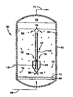
Figure 3 is a simple schematic of an HCS slurry reactor 60 which comprises a
steel cylindrical vessel 62 containing a three phase, reactive HCS slurry 64
within, in
which a gas disengaging and catalyst rejuvenating means 10 of the invention is
shown as
being totally immersed in the slurry. The syngas is introduced into the bottom
of the
reactor via gas line 66 and is bubbled up into the slurry by suitable gas
distribution
means (not shown) horizontally arranged across the surface of gas and liquid
impermeable plate 70, which is sealed to the interior of the vertical wall 63
of vessel 62.
Bubbles 72 of unreacted syngas and gas products of the HCS reaction rise up
through
and out of the slurry into gas disengaging and collecting zone 73 and are
removed from
the reactor via line 74. Not shown is filtration means, such as one or more
liquid filters
in the reactive slurry 64 or in one or more filtration vessels external of the
reactor. Such
filtration means separate the hydrocarbon slurry liquid from the catalyst
particles as
filtrate, and pass the filtrate to further processing and upgrading. Magnetic
means may
also be used to separate the catalyst particles from the hydrocarbon liquid
product if the
catalyst particles are magnetic or paramagnetic, as is disclosed in the prior
art. As
shown in Figure 1, the gas disengaging and catalyst rejuvenating means of the
invention
comprises a vertical, hollow tube or pipe 12, open at its top and bottom, with
the gas
disengaging cup 22 surrounding the bottom of the tube. The interior of the
tube 12 is
the catalyst rejuvenating zone and is provided with rejuvenating gas injecting
means 18
for injecting catalyst rejuvenating gas into the interior of the tube near the
bottom
thereof. A simple cone shaped bai~le plate 36 is disposed below the opening or
orifice
35 at the bottom of the cup 22 to prevent the uprising reactive gas from
entering into
either the annular gas disengaging space 24 or the rejuvenating zone 20.
Arrows 76
indicate the downward flow of the slurry containing the reversibly deactivated
catalyst
particles into the gas disengaging zone 24 and arrows 78 indicate the outward
flow and
return of the catalyst rejuvenated slurry back into the scurry in the reaction
zone (the
slurry body) out the top of the rejuvenation conduit 12.
The uprising syngas serves to maintain the catalyst particles in suspension in
the
hydrocarbon slurry liquid. As soon as slurry enters a relatively quiescent
zone in which
CA 02286241 1999-10-06
WO 98/50486 PCTIUS98/08686
-9-
the uprising gas bubbles do not enter, the lighter gas bubbles immediately
begin
disengaging from the slurry liquid. At the same time, the heavier catalyst
particles begin
to settle out due to gravity and the Lack of the uplifting effect of the
reactive gas
bubbles. Thus, the annular zone 24 between the inner wall surface of the cup
22 and the
outer wall surface of the rejuvenation tube 12 provides a quiescent zone for
the slurry
passing down through the zone. The outer wall of the cup and the baffle
prevent
uprising gas from entering the quiescent zone and gas bubbles immediately
begin
disengaging from the slurry as soon as it enters the zone. The volumetric size
of the
zone; its length, slurry flow rate and gas disengaging rate are factored to
size the zone
so as to effectively remove most of the gas bubbles before the slurry enters
up into the
bottom 16 of the rejuvenation tube. The slurry flow rate through the tube is
determined
in Iarge measure by the tube diameter and rejuvenation gas flow rate. Bubble
rise
velocity is a strong function of the bubble size and the gas disengaging cup
is sized so
that the downward velocity of the slurry (total flow divided by the
disengaging means
cross sectional area) is less than the rise velocity of the smallest bubbles
it is desired to
remove. Studies have shown that as much or more than 90 % of the gas bubbles
may be
removed from the slurry in this manner, before it goes into the rejuvenation
tube. The
catalyst settling rate must also be taken into account to prevent the catalyst
particles
from plugging or slowing the flow of slurry into the rejuvenating zone. Thus,
while an
orifice or nozzle at the bottom of the cup or disengaging zone may not always
be
necessary, it serves as insurance in the event of an imbalance in the slurry
reactor, such
as a slumped bed catalyst condition in which the catalyst concentration toward
the
bottom of the slurry is temporarily greater than what the disengaging and
rejuvenating
means was designed for, which could cause catalyst accumulation at the bottom
of the
cup. The gas disengaging means and the catalyst rejuvenating means have been
illustrated as having a cylindrical cross section, but other shapes such as
rectilinear and
polygonal could be used if desired. While the rejuvenation tube is shown as
vertical and
wholly immersed in the slurry, some departures from vertical may be used and
the tube
or conduit may be bent to accommodate other mechanical devices in the reactor.
However, vertical orientation is preferred. In one embodiment, which is a
preferred
CA 02286241 1999-10-06
WO 98/50486 PCT/US98/08686
~ 10-
embodiment, the top of the rejuvenation zone or conduit may extend up out of
the top
of the slurry and/or feed the catalyst rejuvenated slurry to gas separating
means (not
shown) for separating and removing offgas formed by the catalyst rejuvenation
from the
rejuvenated catalyst slurry. The slurry from which the offgas has been removed
is then
passed back into the slurry body or elsewhere. Another aspect of the present
invention
is that of concentrating the catalyst in the slurry in the gas disengaging
zone, which
occurs by virtue of releasing the gas bubbles to form a denser slurry in which
the catalyst
is more concentrated. The hydrogen or hydrogen containing catalyst
rejuvenation gas
injected into the rejuvenation zone comprises hydrogen which may contain other
gasses
such as nitrogen, C02, H20, CH4, C2-C4+ hydrocarbons, and also CO (as long as
the
mole ratio of the H2 to CO) is sufficient to remove the CO and still at least
partially
rejuvenate the catalyst.
As disclosed in U.S. Patent 5,288,673, the degree of catalyst rejuvenation can
be
controlled by independently controlling the slurry temperature in the
rejuvenating zone
irrespective of the temperature of the main body of slurry in the surrounding
HCS
reaction zone. This patent discloses that temperature control in the
rejuvenation zone or
tubes is achieved by one or more of either increasing or decreasing the slurry
residence
time in the zone, so as to utilize the exothermic nature of the rejuvenation
reactions, by
insulating the rejuvenation tubes, by introducing heat or a cooling medium
into the zone,
by preheating the rejuvenation gas, etc. The '673 patent teaches that the
temperature in
the rejuvenation zone should be high enough to remove CO and at least
partially
rejuvenate the catalyst and low enough to minimize methane formation and wax
(~CZO.,.
alkanes) hydrogenolysis. These teachings apply to the present invention also.
In an HCS process, liquid and gaseous hydrocarbon products are formed by
contacting a syngas comprising a mixture of H2 and CO with a suitable Fischer-
Tropsch
type of HCS catalyst, under shifting or non-shifting conditions and preferably
non-
shifting conditions in which little or no water gas shift reaction occurs,
particularly when
the catalytic metal comprises Co, Ru or mixture thereof. Suitable Fischer-
Tropsch
CA 02286241 1999-10-06
WO 98/50486 PCT/US98/08686
-11-
reaction types of catalysts comprise, for example, one or more Group VIII
catalytic
metals such as Fe, Ni, Co, Ru and Re. In one embodiment the catalyst comprises
cataiytically effective amounts of Co and one or more of Re, Ru, Fe, Ni, Th,
Zr, Hf, U,
Mg, La on a suitable inorganic support material, preferably one which
comprises one or
more refractory metal oxides. Preferred supports for Co containing catalysts
comprise
titania, particularly when employing a slurry HCS process in which higher
molecular
weight, primarily paraffinic liquid hydrocarbon products are desired. Useful
catalysts
and their preparation are known and illustrative, but nonlimiting examples may
be found,
for example, in U.S. Patents 4,568,663; 4,663,305; 4,542,122; 4,621,072 and
5,545,674..
The hydrocarbons produced by an HCS process according to the invention are
typically upgraded to more valuable products, by subjecting all or a portion
of the C~+.
hydrocarbons to fractionation and/or conversion. By conversion is meant one or
more
operations in which the molecular structure of at least a portion of the
hydrocarbon is
changed and includes both noncatalytic processing (e.g., steam cracking), and
catalytic
processing (e.g., catalytic cracking) in which a fraction is contacted with a
suitable
catalyst. If hydrogen is present as a reactant, such process steps are
typically referred to
as hydroconversion and include, for example, hydroisomerization,
hydrocracking,
hydrodewaxing, hydrorefining and the more severe hydrorefining referred to as
hydrotreating, all conducted at conditions well known in the literature for
hydroconversion of hydrocarbon feeds, including hydrocarbon feeds rich in
paraffins.
Illustrative, but nonlimiting examples of more valuable products formed by
conversion
include one or more of a synthetic crude oil, liquid fuel, olefins, solvents,
lubricating,
industrial or medicinal oil, waxy hydrocarbons, nitrogen and oxygen containing
compounds, and the like. Liquid fuel includes one or more of motor gasoline,
diesel
fuel, jet fuel, and kerosene, while lubricating oil includes, for example,
automotive, jet,
turbine and metal working oils. Industrial oil includes well drilling fluids,
agricultural
oils, heat transfer fluids and the like.
CA 02286241 1999-10-06
WO 98/50486 PCT/US98/08686
-12-
It is understood that various other embodiments and modifications in the
practice
of the invention will be apparent to, and can be readily made by, those
skilled in the art
without departing from the scope and spirit of the invention described above.
Accordingly, it is not intended that the scope of the claims appended hereto
be limited to
the exact description set forth above, but rather that the claims be construed
as
encompassing all of the features of patentable novelty which reside in the
present
invention, including all the features and embodiments which would be treated
as
equivalents thereof by those skilled in the art to which the invention
pertains.