Some of the information on this Web page has been provided by external sources. The Government of Canada is not responsible for the accuracy, reliability or currency of the information supplied by external sources. Users wishing to rely upon this information should consult directly with the source of the information. Content provided by external sources is not subject to official languages, privacy and accessibility requirements.
Any discrepancies in the text and image of the Claims and Abstract are due to differing posting times. Text of the Claims and Abstract are posted:
| (12) Patent: | (11) CA 2286280 |
|---|---|
| (54) English Title: | JOINING METAL COMPONENTS |
| (54) French Title: | ELEMENTS METALLIQUES D'ASSEMBLAGE |
| Status: | Expired and beyond the Period of Reversal |
| (51) International Patent Classification (IPC): |
|
|---|---|
| (72) Inventors : |
|
| (73) Owners : |
|
| (71) Applicants : |
|
| (74) Agent: | ROBIC AGENCE PI S.E.C./ROBIC IP AGENCY LP |
| (74) Associate agent: | |
| (45) Issued: | 2007-03-27 |
| (86) PCT Filing Date: | 1998-04-17 |
| (87) Open to Public Inspection: | 1998-10-29 |
| Examination requested: | 2003-01-21 |
| Availability of licence: | N/A |
| Dedicated to the Public: | N/A |
| (25) Language of filing: | English |
| Patent Cooperation Treaty (PCT): | Yes |
|---|---|
| (86) PCT Filing Number: | PCT/AU1998/000271 |
| (87) International Publication Number: | AU1998000271 |
| (85) National Entry: | 1999-10-05 |
| (30) Application Priority Data: | ||||||
|---|---|---|---|---|---|---|
|
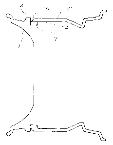
This invention concerns a method of joining forged,
machined, formed or cast components with metal tube.
In another aspect it concerns a metal object constructed
according to the method. The tube heated to expand its
diameter, but not sufficiently to anneal it, or otherwise
adversely affect its mechanical properties. Then, while
the tube is still hot, it is pushed over part of the
central component so that part of the tube overlies a
circumferential groove in the central component. Then,
while still hot, the circumferential part of the tube which
overlies the groove, is rolled into the groove, so that when
cooled the rolled pan of the tube is clamped into the
groove. The invention is particularly, but not exclusively,
applicable to the construction of vehicle wheels having a
forged, machined, formed or cast hub or centre and a
metal rim.
L'invention concerne un procédé pour assembler des éléments forgés, usinés ou moulés à un tube métallique. Selon un autre aspect, l'invention traite d'un objet métallique construit selon ce procédé. Le tube est chauffé de manière à assurer la dilatation de son diamètre, mais en évitant qu'il ne soit recuit, c'est-à-dire, en évitant des effets défavorables sur ses propriétés mécaniques. Ainsi, pendant que le tube est encore chaud, il est poussé sur une partie de l'élément central de telle sorte qu'il vienne recouvrir une rainure circonférentielle ménagée dans l'élément central. Ainsi, pendant qu'elle est encore chaude, la partie circonférentielle du tube qui recouvre la rainure, est roulée pour pénétrer dans la rainure, et une fois refroidie, elle est fixée, par serrage, dans cette rainure. L'invention s'applique, mais non exclusivement, à la construction de roues de véhicules, comportant un moyen ou centre forgé, usiné, formé ou moulé et une jante métallique.
Note: Claims are shown in the official language in which they were submitted.
Note: Descriptions are shown in the official language in which they were submitted.
2024-08-01:As part of the Next Generation Patents (NGP) transition, the Canadian Patents Database (CPD) now contains a more detailed Event History, which replicates the Event Log of our new back-office solution.
Please note that "Inactive:" events refers to events no longer in use in our new back-office solution.
For a clearer understanding of the status of the application/patent presented on this page, the site Disclaimer , as well as the definitions for Patent , Event History , Maintenance Fee and Payment History should be consulted.
| Description | Date |
|---|---|
| Time Limit for Reversal Expired | 2013-04-17 |
| Letter Sent | 2012-04-17 |
| Inactive: Correspondence - MF | 2010-08-10 |
| Grant by Issuance | 2007-03-27 |
| Inactive: Cover page published | 2007-03-26 |
| Inactive: Final fee received | 2007-01-11 |
| Pre-grant | 2007-01-11 |
| Notice of Allowance is Issued | 2006-08-30 |
| Letter Sent | 2006-08-30 |
| Notice of Allowance is Issued | 2006-08-30 |
| Inactive: Office letter | 2006-08-29 |
| Inactive: Entity size changed | 2006-08-29 |
| Inactive: Approved for allowance (AFA) | 2006-08-02 |
| Inactive: Corrective payment - s.78.6 Act | 2006-07-04 |
| Inactive: IPC from MCD | 2006-03-12 |
| Inactive: IPC from MCD | 2006-03-12 |
| Inactive: IPC from MCD | 2006-03-12 |
| Inactive: IPC from MCD | 2006-03-12 |
| Amendment Received - Voluntary Amendment | 2006-01-10 |
| Inactive: S.30(2) Rules - Examiner requisition | 2005-07-14 |
| Letter Sent | 2003-02-20 |
| Request for Examination Received | 2003-01-21 |
| Request for Examination Requirements Determined Compliant | 2003-01-21 |
| All Requirements for Examination Determined Compliant | 2003-01-21 |
| Small Entity Declaration Determined Compliant | 2000-03-14 |
| Inactive: Cover page published | 1999-11-25 |
| Inactive: First IPC assigned | 1999-11-24 |
| Inactive: IPC assigned | 1999-11-24 |
| Inactive: IPC assigned | 1999-11-24 |
| Inactive: Notice - National entry - No RFE | 1999-11-12 |
| Application Received - PCT | 1999-11-08 |
| Application Published (Open to Public Inspection) | 1998-10-29 |
There is no abandonment history.
The last payment was received on 2006-03-13
Note : If the full payment has not been received on or before the date indicated, a further fee may be required which may be one of the following
Patent fees are adjusted on the 1st of January every year. The amounts above are the current amounts if received by December 31 of the current year.
Please refer to the CIPO
Patent Fees
web page to see all current fee amounts.
| Fee Type | Anniversary Year | Due Date | Paid Date |
|---|---|---|---|
| Basic national fee - small | 1999-10-05 | ||
| MF (application, 2nd anniv.) - small | 02 | 2000-04-17 | 2000-04-07 |
| MF (application, 3rd anniv.) - small | 03 | 2001-04-17 | 2001-03-22 |
| MF (application, 4th anniv.) - standard | 04 | 2002-04-17 | 2002-03-19 |
| Request for examination - standard | 2003-01-21 | ||
| MF (application, 5th anniv.) - standard | 05 | 2003-04-17 | 2003-03-26 |
| MF (application, 6th anniv.) - standard | 06 | 2004-04-19 | 2004-03-19 |
| MF (application, 7th anniv.) - standard | 07 | 2005-04-18 | 2005-03-18 |
| MF (application, 8th anniv.) - standard | 08 | 2006-04-17 | 2006-03-13 |
| Final fee - small | 2007-01-11 | ||
| MF (patent, 9th anniv.) - small | 2007-04-17 | 2007-03-15 | |
| MF (patent, 10th anniv.) - small | 2008-04-17 | 2008-03-19 | |
| MF (patent, 11th anniv.) - small | 2009-04-17 | 2009-03-19 | |
| MF (patent, 12th anniv.) - small | 2010-04-19 | 2010-03-17 | |
| MF (patent, 13th anniv.) - small | 2011-04-18 | 2011-03-15 |
Note: Records showing the ownership history in alphabetical order.
| Current Owners on Record |
|---|
| ANTHONY GRANT SIMMONS |
| Past Owners on Record |
|---|
| None |

