Language selection

Search

Patent 2286434 Summary

Third-party information liability

Some of the information on this Web page has been provided by external sources. The Government of Canada is not responsible for the accuracy, reliability or currency of the information supplied by external sources. Users wishing to rely upon this information should consult directly with the source of the information. Content provided by external sources is not subject to official languages, privacy and accessibility requirements.

Claims and Abstract availability

Any discrepancies in the text and image of the Claims and Abstract are due to differing posting times. Text of the Claims and Abstract are posted:

  • At the time the application is open to public inspection;
  • At the time of issue of the patent (grant).
(12) Patent Application: (11) CA 2286434
(54) English Title: OPTICAL SYSTEM CAPABLE OF CREATING THE THREE-DIMENSIONAL IMAGE ON AN OBJECT IN SPACE WITHOUT IMAGE INVERSION
(54) French Title: SYSTEME OPTIQUE PERMETTANT DE CREER L'IMAGE TRIDIMENSIONNELLE D'UN OBJET DANS L'ESPACE SANS INVERSION D'IMAGE
Status: Deemed Abandoned and Beyond the Period of Reinstatement - Pending Response to Notice of Disregarded Communication
Bibliographic Data
(51) International Patent Classification (IPC):
(72) Inventors :
  • DOMINGUEZ-MONTES, JUAN (Spain)
  • GOMEZ-MARTIN, JESUS MARCOS (Spain)
  • CIENFUEGOS-JOVELLANOS, JOSE MARIA (Sweden)
(73) Owners :
  • JUAN DOMINGUEZ-MONTES
  • JESUS MARCOS GOMEZ-MARTIN
  • JOSE MARIA CIENFUEGOS-JOVELLANOS
(71) Applicants :
  • JUAN DOMINGUEZ-MONTES (Spain)
  • JESUS MARCOS GOMEZ-MARTIN (Spain)
  • JOSE MARIA CIENFUEGOS-JOVELLANOS (Sweden)
(74) Agent: SMART & BIGGAR LP
(74) Associate agent:
(45) Issued:
(22) Filed Date: 1999-10-14
(41) Open to Public Inspection: 2000-04-16
Availability of licence: N/A
Dedicated to the Public: N/A
(25) Language of filing: English

Patent Cooperation Treaty (PCT): No

(30) Application Priority Data:
Application No. Country/Territory Date
98500227.8 (European Patent Office (EPO)) 1998-10-16

Abstracts

English Abstract


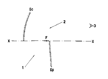
The optical system comprises a convergent mirror (E c) and a
plane mirror (E p), which are duly positioned in order for the focus (F)
established in the optical axis (X-X) of the convergent mirror (E c) in
turn to be located in the sector lying between both mirrors. An object
(I1-I2) located in an area (1) is first reflected onto the plane mirror (E p)
and then onto the convergent mirror (E c), yielding an image (I''1-I''2) in
an area (2) opposite the area (1) in a normal position for an observer
located at a point (O) outside the system, i.e. in such a position that the
signs are legible.


Claims

Note: Claims are shown in the official language in which they were submitted.

-7-
CLAIMS
1.- An optical system capable of creating the three-dimensional
image of an object in space without image inversion, designed to be
capable of offering an image in its normal position with the signs
accurately reproduced and in a legible position, the image being
observed in three dimensions, characterised in that it comprises two
mirrors, namely a convergent mirror (E c) and a plane mirror (E p), being
particular in that the focus (F) of the convergent mirror (E c) is located
on the axis (X-X) of said mirror and in the sector lying between both
mirrors, the mirrors having been designed to be located so that an
object lying in an area (1) provided below the optical axis (X-X) is first
reflected onto the plane mirror (E p) and then onto the convergent mirror
(E c) and its image is seen three-dimensionally in an area (2) located
above the optical axis (X-X), being the area where an observer (O) is
located, said three-dimensional image being reproduced in its normal
position and with its signs directly legible.
2.- An optical system capable of creating the three-dimensional
image of an object in space without image inversion, as claim 1,
characterised in that the convergent (E c) and plane (E p) mirrors are
suitably arranged within a prismatic-rectangular body (3), with an area
(1) for locating the object for which a three-dimensional image is to be
created, and with a window (4) provided on a wall opposite the wall
where the convergent mirror (E c) is positioned, the three-dimensional
image being visible through said window in the area (2) outside said
prismatic body (3) from the observer's (O) area.
3.- An optical system capable of creating the three-dimensional
image of an object in space without image inversion, as claims 1 and 2,
characterised in that the object is a genuine object.
4.- An optical system capable of creating the three-dimensional
image of an object in space without image inversion, as claims 1 and 2,
characterised in that the object is a flat or otherwise shaped diffusing

-8-
surface onto or in which a TV or cinematographic image is projected or
created.

Description

Note: Descriptions are shown in the official language in which they were submitted.


CA 02286434 1999-10-14
-1-
OPTICAL SYSTEM CAPABLE OF CREATING THE THREE
DIMENSIONAL IMAGE OF AN OBJECT IN SPACE
WITHOUT IMAGE INVERSION
SPECIFICATION
OBJECT OF THE INVENTION
The invention relates to an optical system with which the three-
dimensional image of a genuine object is created in space, which image
is observed in its normal position, i.e. without a specular inversion.
The object of the invention is providing a very simple optical
system which nevertheless allows an image to be shown in its normal
position, i.e. with properly reproduced signs, the three-dimensional
image being observed by merely using a concave mirror, a plane mirror
and the very object, all properly positioned.
BACKGROUND OF THE INVENTION
Several optical systems are known to allow a three-dimensional
image created based on an object to be seen, some of which systems
are straightforward but nevertheless have the drawback that the images
reproduced have their signs specularly inverted from left to right and
are therefore almost illegible, all of which requires that the objects be
labelled with specularly inverted characters and words and phrases be
written from right to left in order to allow them to be properly read on
observing the three-dimensional image.
There are also more complex optical systems which comprise a
greater number of elements or more sophisticated elements, such as
semi-transparent and/or polarised sheets, which may, depending on
their position, generate unwanted simultaneous images of the object, of
the observers themselves or of elements existing in their surroundings.

CA 02286434 1999-10-14
-2-
In conclusion, creating a three-dimensional image in space is
achieved either with inverted signs or based on more complex systems
which may generate other images along with the image of the object.
DESCRIPTION OF THE INVENTION
The system subject hereof has been devised to fully solve the
aforesaid drawbacks based upon a simple and effective solution, for it
overcomes the disadvantages of the simple devices or systems in which
the signs are shown inverted and also overcomes the sophisticated and
complex systems mentioned in the second place, providing an image in
its normal position and with properly reproduced signs, based upon a
structurally simple solution.
More specifically, the inventive system relies on the arrangement
of two mirrors, namely a concave and a plane mirror, such that the
optical axis of the concave or convergent mirror and on which its focus
is contained delimits two areas, to wit an upper area where the concave
or convergent mirror is precisely located, and a bottom area in which
the plane mirror is located, such that the former's focus is located on
the optical axis, between both mirrors, the mirrors having a reflecting
surface facing their common inner area.
With this arrangement, the object for which a three-dimensional
image is sought will be placed inverted, facing the reflecting surface of
the plane mirror and below the optical axis of the concave or
convergent mirror, thereby a three-dimensional image to be obtained on
the opposite area, i.e. above the optical axis and outside the area
common to both mirrors, which is the logically area where the observer
is located. The three-dimensional image obtained is reproduced in its
normal position and with perfectly legible signs.
As used herein, the term object should be taken to have not only
its vernacular meaning, i.e. any genuine object, but also the meaning it
has for optical professionals, i.e. any diffusing surface from which

CA 02286434 1999-10-14
-3-
photons are let off, namely for instance a cathode-ray tube screen, a
surface of whatever shape onto which cinematographic or TV images
are projected, etc.
DESCRIPTION OF THE DRAWINGS
In order to provide a fuller description and contribute to the
complete understanding of the characteristics of this invention, in
accordance with a preferred embodiment thereof, a set of drawings is
attached to the present specification as an integral part thereof which,
while purely illustrative and not fully comprehensive, shows the
following:
Figure 1.- Shows the arrangement of the optical system made in
accordance with the object of the present invention, or in other words
the position of the concave or convergent mirror and the plane mirror,
along with the former's optical axis and its respective focus.
Figure 2.- Shows how the successive images of the point of an
object are formed, respectively produced by the plane mirror and by the
two mirrors together.
Figure 3.- Shows successive images of an object, respectively
produced by the plane mirror and by the two mirrors together.
Figure 4.- Schematically shows the manner in which the central
part of an object and its respective images would be seen.
Figure 5.- Is a schematic representation of how the inventive
system might conceivably be assembled within a prismatic body having
a rectangular base.

CA 02286434 1999-10-14
-4-
PREFERRED EMBODIMENT OF THE INVENTION
With reference to the above figures, the inventive system
comprises a concave or convergent mirror (E~) and a plane mirror (EP),
and therefore the focus (F) of said convergent mirror (E~) is located on
the respective optical axis (X-X) of said mirror and in the sector lying
between both mirrors. The mirrors may be seen to be positioned with a
slight inclination and the area generally marked ( 1 ) would be where an
object for which a three-dimensional image is to be created would be
positioned, such area (1) lying below the optical axis (X-X) and
between both mirrors, whereas the area (2) is the area in which the
three-dimensional image of the object would be created or reproduced,
viewed by the observer marked (O), as is clearly shown in figure 1.
Figure 2 shows the path followed by the light rays in forming the
images of a point (p) of an object, the light rays therefore starting from
point (p) and being reflected on the plane mirror (Ep) so as to converge
at point (p') which is the image of point (p) aforesaid.
Said point or image (p') lies at the same distance (d) from mirror
(Ep) as point (p), albeit on the opposite side of said mirror.
Furthermore, the light rays are then reflected on the convergent
mirror (E~), converging at point (p"), which is the image of point (p)
produced by the optical system as a whole.
In paraxial conditions, the distances (d') and (d"), that is to say
the distances from point (p') and image (p") to point (C), measured
along axis (X-X) of mirror (E~), are related by the expression:
1 + 1 - 1
d" d' f
where (f) represents the focal length of the convergent mirror (E~).

CA 02286434 1999-10-14
- 5 -
Similarly, the images of all the points of the objects located in
area ( 1 ) are produced in area (2).
Figure 3 shows the images (I'~-I'2) and (I"1-I"2) produced based
on object (I~-I2), wherein the latter is located in an inverted upside
down position with respect to its normal position, and may clearly be
seen that image (I'~-I'2) has the same inverted position as the object
(Il-I2), moreover being inverted from left to right which cannot be seen
in the figure, whereas the final image (I" ~-I"2) is formed in the normal
position.
Figure 4 shows the various appearances of an object and its
successive images, and it can be seen at (a) that an observer (O) lying
on the side of the plane mirror (Ep) sees the object (I~-I2) in an inverted
upside down position with respect to its normal position.
It may be seen in said same figure 4 that the image (I'~-I'2) of the
object produced by the plane mirror is shown with the sign inverted
from right to left, the observer (O) lying on the same side of the mirror
as the actual object.
At (c) of this figure 4, an observer lying in the area (2), which is
the observer's (O) area, is shown to see the final image (I" 1-I"2)
generated by the inventive optical system, after a double inversion has
taken place to obtain the image of the object in its normal position, and
with the sign written properly.
In an exemplary assembly of the above-described optical system,
shown in figure 5, said system consists of a prismatic enclosure (3)
within which the concave or convergent mirror (E~) and the plane
mirror (Ep) are suitably arranged, ensuring that they are all properly
positioned.
An appropriate space (1) is established within this prismatic
body (3) to locate the object for which an image is to be created, being

CA 02286434 1999-10-14
-6-
either a real object which may be supported by drive means to provide
it with various movements, or an object within the optical meaning, i.e.
a flat or otherwise shaped surface of a projection system or a cathode-
ray tube.
The image is formed in the space (2) lying outside the enclosure
as the observer's (O) area, which image is achieved based on the light
rays coming from the object, through said optical system, which are
projected or leave through the window (4), the image being seen in the
area (2) when the observer is located at the point or in the area marked
(0).

Representative Drawing
A single figure which represents the drawing illustrating the invention.
Administrative Status

2024-08-01:As part of the Next Generation Patents (NGP) transition, the Canadian Patents Database (CPD) now contains a more detailed Event History, which replicates the Event Log of our new back-office solution.

Please note that "Inactive:" events refers to events no longer in use in our new back-office solution.

For a clearer understanding of the status of the application/patent presented on this page, the site Disclaimer , as well as the definitions for Patent , Event History , Maintenance Fee  and Payment History  should be consulted.

Event History

Description Date
Inactive: IPC expired 2020-01-01
Inactive: IPC from MCD 2006-03-12
Application Not Reinstated by Deadline 2003-10-14
Time Limit for Reversal Expired 2003-10-14
Deemed Abandoned - Failure to Respond to Maintenance Fee Notice 2002-10-15
Letter Sent 2001-12-28
Inactive: Entity size changed 2001-12-28
Reinstatement Requirements Deemed Compliant for All Abandonment Reasons 2001-12-07
Deemed Abandoned - Failure to Respond to Maintenance Fee Notice 2001-10-15
Application Published (Open to Public Inspection) 2000-04-16
Inactive: Cover page published 2000-04-16
Inactive: Filing certificate - No RFE (English) 2000-02-18
Request for Priority Received 2000-01-27
Inactive: Filing certificate correction 1999-12-13
Inactive: First IPC assigned 1999-11-26
Inactive: Filing certificate - No RFE (English) 1999-11-18
Filing Requirements Determined Compliant 1999-11-18
Letter Sent 1999-11-16
Inactive: Inventor deleted 1999-11-10
Application Received - Regular National 1999-11-09
Inactive: Applicant deleted 1999-11-09

Abandonment History

Abandonment Date Reason Reinstatement Date
2002-10-15
2001-10-15

Maintenance Fee

The last payment was received on 2001-12-07

Note : If the full payment has not been received on or before the date indicated, a further fee may be required which may be one of the following

  • the reinstatement fee;
  • the late payment fee; or
  • additional fee to reverse deemed expiry.

Please refer to the CIPO Patent Fees web page to see all current fee amounts.

Fee History

Fee Type Anniversary Year Due Date Paid Date
Application fee - small 1999-10-14
MF (application, 2nd anniv.) - standard 02 2001-10-15 2001-12-07
Reinstatement 2001-12-07
Owners on Record

Note: Records showing the ownership history in alphabetical order.

Current Owners on Record
JUAN DOMINGUEZ-MONTES
JESUS MARCOS GOMEZ-MARTIN
JOSE MARIA CIENFUEGOS-JOVELLANOS
Past Owners on Record
None
Past Owners that do not appear in the "Owners on Record" listing will appear in other documentation within the application.
Documents

To view selected files, please enter reCAPTCHA code :


To view images, click a link in the Document Description column. To download the documents, select one or more checkboxes in the first column and then click the "Download Selected in PDF format (Zip Archive)" or the "Download Selected as Single PDF" button.

List of published and non-published patent-specific documents on the CPD .

If you have any difficulty accessing content, you can call the Client Service Centre at 1-866-997-1936 or send them an e-mail at CIPO Client Service Centre.


Document
Description 
Date
(yyyy-mm-dd) 
Number of pages   Size of Image (KB) 
Representative drawing 2000-04-07 1 2
Cover Page 2000-04-07 1 34
Description 1999-10-14 6 249
Claims 1999-10-14 2 61
Drawings 1999-10-14 3 38
Abstract 1999-10-14 1 22
Filing Certificate (English) 1999-11-18 1 164
Filing Certificate (English) 2000-02-18 1 164
Reminder of maintenance fee due 2001-06-18 1 112
Courtesy - Abandonment Letter (Maintenance Fee) 2001-11-13 1 183
Notice of Reinstatement 2001-12-28 1 172
Courtesy - Abandonment Letter (Maintenance Fee) 2002-11-12 1 179
Correspondence 1999-11-18 1 10
Correspondence 1999-12-13 1 45
Fees 2001-12-07 2 73