Language selection

Search

Patent 2286437 Summary

Third-party information liability

Some of the information on this Web page has been provided by external sources. The Government of Canada is not responsible for the accuracy, reliability or currency of the information supplied by external sources. Users wishing to rely upon this information should consult directly with the source of the information. Content provided by external sources is not subject to official languages, privacy and accessibility requirements.

Claims and Abstract availability

Any discrepancies in the text and image of the Claims and Abstract are due to differing posting times. Text of the Claims and Abstract are posted:

  • At the time the application is open to public inspection;
  • At the time of issue of the patent (grant).
(12) Patent Application: (11) CA 2286437
(54) English Title: ADAPT-A-TRACK
(54) French Title: CHENILLE
Status: Deemed Abandoned and Beyond the Period of Reinstatement - Pending Response to Notice of Disregarded Communication
Bibliographic Data
Abstracts

English Abstract


The present invention relates to a tracks system adaptable
to a motorized vehicle. This track system allow vehicle such as
ambulance and police cruiser to travel on snow or muddy terrain.
The present invention also include a new type of easy to built
track crosslink.


Claims

Note: Claims are shown in the official language in which they were submitted.

4
The embodiments of the invention in which an exclusive
property or privilege is claimed are defined as follows:
-Any track system that fit under or in the side of a motor
vehicle and that uses the driving wheel friction of that vehicle
to power those tracks.
-Any motor vehicle adaptable track system that use the difference
of diametre of conical rollers to steer the tracks.
-Any crosslink design that would allow the tires to run on a flat
surface by installing the sprocket out of center in relation with
these tires.

Description

Note: Descriptions are shown in the official language in which they were submitted.


CA 02286437 1999-10-OS
2
Specification
The purpose of this invention is to provide extra traction
and flotation to regular motor vehicle like pick-up trucks,
ambulances, police cruisers, and more. My invention consist of
an adaptable track system that is driven by the driving wheels of
a motor vehicle temporarly installed on this track system. Other
similar product on the market are installed in replacment of the
motor vehicle wheels, but these system offer less traction and
flotation, and they also put a lot of strain on the steering
linkage of the motor vehicle. Also part of the system is a new
concept of steel crosslink that offer a smoother ride than
conventional crosslink, due to the facts that the tire and the
sprocket are not installed with the same centerline, thus
allowing the tire to run directly on one of the belts joining the
crosslinks.
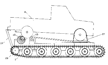
Description of the drawing, Fig. 1 represent the crosslink
of the Adapt-a-track system. Fig. 2 represent a crosslink
version that could be used for wider track system. Fig. 3
represent an elevation view of the Adapt-a-track system with a
motor vehicle installed on it. Fig. 4 represent the rear view of
the Adapt-a-track system with a motor vehicle installed on it.
Fig. 5 represent a top view of the Adapt-a-track system with the
four wheels of the motor vehicle that would drive and steer the
track system. Fig. 6 represent an elevation view of the Adapt-a-
track system with the trailer wheels in function and with the
trailer tongue and access ramps installed.
The track system include three main assembly; the tracks,
the frame, and the drive assembly.
The track assembly consist of one or more rubber belt (4)
forming a close loop with perpendiculary attached "T" shaped
steel or aluminium pieces (1). Those "T" shaped crosslinks (1)
are position in a way to have the widest of its flat sides in
contact with the belt (4). Wheel guides (3) are installed on the
opposite of the crosslinks (1), these wheel guides (3) are fasten
to the crosslinks (1) with through the belt (4) fasteners (5). A
half round pieces (2) is welded or fastened over the widest flat
part of the crosslink (1) in a way to have a sprocket drive the
whole assembly.
The frame assembly include rectangular frame (7) under which
axles (8) are attached, at the ends of these axles (8) are wheels
(6) supporting the track assemblies. On the top of the frame (7)
is a structure allowing a motor vehicle (9) to be positioned and
secured on the drive assembly. A piece of structure (10) secure
the back of the vehicle (9) to the frame (7). The front wheels
of the vehicle (9) are secured to the turn tables (14) with tie-
downs (27). A set of wheels (6) are located in the frame (7),

CA 02286437 1999-10-OS
3
those wheels (6) can be lowered in a way to support the complete
track system. One end of the frame (7) as a removable trailer
tongue (12). The frame (7) end opposite of the drive assembly as
two removable access ramp (13) which permit a motor vehicle (9)
to be driven on and off the track system.
The drive assembly consist of: two turntables (14) with
linkage (26), two cylindrical idler rolls (15) with commun shaft
(16) and bearing (17), two conical driven rolls (18) with drive
shaft (19), bearings (20), support frame (21), and two gear
reducer (22) with sprockets (23).
The two turntables (14) are fitted under the steering wheels
of the motor vehicle (9) and, as the wheels are steered, the
attached linkage system (26) move the conical rolls (18) assembly
from one side to another, thus driving the tracks at different
speeds and steering the tracked vehicle. The cylindrical rolls
(15) are joint by a shaft (16) mounted on bearing (17) resting on
the frame (7). The two conical rolls (18) are mounted on
bearings (20) resting on a seperate frame (21) that allow for
lateral movement commanded by the linkage (26) of the turntable
(14). Each conical rolls (18) can turn independent from one
another and each of them drive the gear reducer (22) on the
opposite side with the mean of a telescopic drive shaft (19). A
sprocket (23) is mounted on each gear reducer (22) and fits in
the drive pattern of the crosslinks (1).

Representative Drawing
A single figure which represents the drawing illustrating the invention.
Administrative Status

2024-08-01:As part of the Next Generation Patents (NGP) transition, the Canadian Patents Database (CPD) now contains a more detailed Event History, which replicates the Event Log of our new back-office solution.

Please note that "Inactive:" events refers to events no longer in use in our new back-office solution.

For a clearer understanding of the status of the application/patent presented on this page, the site Disclaimer , as well as the definitions for Patent , Event History , Maintenance Fee  and Payment History  should be consulted.

Event History

Description Date
Inactive: IPC from MCD 2006-03-12
Application Not Reinstated by Deadline 2003-10-06
Time Limit for Reversal Expired 2003-10-06
Inactive: Adhoc Request Documented 2003-07-09
Deemed Abandoned - Failure to Respond to Maintenance Fee Notice 2002-10-07
Application Published (Open to Public Inspection) 2001-04-05
Inactive: Cover page published 2001-04-04
Inactive: First IPC assigned 1999-11-24
Inactive: Office letter 1999-11-10
Inactive: Filing certificate - No RFE (English) 1999-11-09
Inactive: Inventor deleted 1999-11-09
Inactive: Applicant deleted 1999-11-09
Filing Requirements Determined Compliant 1999-11-09
Application Received - Regular National 1999-11-09

Abandonment History

Abandonment Date Reason Reinstatement Date
2002-10-07

Maintenance Fee

The last payment was received on 2001-10-01

Note : If the full payment has not been received on or before the date indicated, a further fee may be required which may be one of the following

  • the reinstatement fee;
  • the late payment fee; or
  • additional fee to reverse deemed expiry.

Please refer to the CIPO Patent Fees web page to see all current fee amounts.

Fee History

Fee Type Anniversary Year Due Date Paid Date
Application fee - small 1999-10-05
MF (application, 2nd anniv.) - small 02 2001-10-05 2001-10-01
Owners on Record

Note: Records showing the ownership history in alphabetical order.

Current Owners on Record
LUC BELZILE
Past Owners on Record
None
Past Owners that do not appear in the "Owners on Record" listing will appear in other documentation within the application.
Documents

To view selected files, please enter reCAPTCHA code :


To view images, click a link in the Document Description column. To download the documents, select one or more checkboxes in the first column and then click the "Download Selected in PDF format (Zip Archive)" or the "Download Selected as Single PDF" button.

List of published and non-published patent-specific documents on the CPD .

If you have any difficulty accessing content, you can call the Client Service Centre at 1-866-997-1936 or send them an e-mail at CIPO Client Service Centre.


Document
Description 
Date
(yyyy-mm-dd) 
Number of pages   Size of Image (KB) 
Representative drawing 2001-03-22 1 13
Drawings 1999-10-05 6 96
Claims 1999-10-05 1 15
Abstract 1999-10-05 1 9
Description 1999-10-05 2 103
Cover Page 2001-03-22 1 28
Filing Certificate (English) 1999-11-09 1 164
Notice: Maintenance Fee Reminder 2001-07-09 1 120
Notice: Maintenance Fee Reminder 2002-07-08 1 130
Courtesy - Abandonment Letter (Maintenance Fee) 2002-11-04 1 179
Second Notice: Maintenance Fee Reminder 2003-04-08 1 121
Notice: Maintenance Fee Reminder 2003-07-08 1 115
Correspondence 1999-11-09 1 7
Fees 2001-10-01 1 71