Note: Descriptions are shown in the official language in which they were submitted.
._ .~ . ' CA 02287083 1999-10-21
METHOD FOR PRODUCING DENTAL REPLACEMENT
Background of the Invention
The present invention relates to method for producing dental
replacements wherein a pre-shaped ceramic part is applied to a
dental support structure or a tooth stump model by a ceramic paste.
The invention also relates to the dental replacement having a pre-
shaped ceramic part that is connected by a ceramic paste to a
dental support structure or a tooth stump model .
Such a method and such a dental replacement are known
from German Offenlegungsschrift 36 04 059. A dental crown
according to this publication is produced by first manufacturing a
hollow cap and placing the hollow cap with the aid of a mineral
dentin replacement material onto a tooth stump, i.e., a tooth stump
model. The excess material which is pressed out by pressing the
cap onto the tooth stump is removed or shaped and, subsequently,
the assembly is fired. This solution is based on the known method
of producing porcelain hollow crowns which are connected by tooth
cement to the tooth stump model whereby instead of the tooth
cement the mineral dentin replacement material is used for
connecting the hollow cap to the tooth stump. This is designed to
reduce the layer thickness of the hollow cap and to thus improve the
-1-
Splanemann - 2657-11-18.996
~
- CA 02287083 1999-10-21
esthetic appearance.
The manufacture of hollow caps according to German
Offenlegungsschlinfs 36 04 059, however, has been difficult and
has shown to be disadvantageous in practice. For example, a
plurality of hollow caps with respective color, size, and shape of
the desired tooth replacement must be premanufactured and stored
so that it is necessary to have an extensive hollow cap supply in
storage. On the other hand, the esthetic result is not satisfactory
because the external shape of the replacement tooth is always a
standard result. The coloration can not accommodate the
differentiation of natural teeth even when, for example, the supply
of 100 different hollow caps is provided which is necessary for five
different colors, five different shapes and four different front teeth.
In contrast, pre-shaped ceramic parts have the advantage
that the shaping of the tooth replacement can be individualized
while, in contrast, it is essentially predetermined for hollow caps.
Since the hollow cap method has not found acceptance, it
has also been suggested to apply multiple ceramic support layers
onto a dental support structure or a tooth stump model in sequence
in order to allow for an individualized esthetic appearance that
closely resembles a natural tooth. The layers can be produced in
-2-
Splanemann - 2657-11-18.996
- CA 02287083 1999-10-21
the dental lab according to an impression. This, for example,
known from U.S. Patent 4,473,353 according to which a
corresponding layer is applied with an acrylic adhesive after a
respective impression has been prepared.
A similarly adhesively connected hollow cap is also known
from U.S. Patent 4,813,874. This method also includes producing
an impression and does not employ premanufacture so that the
work expenditure is relatively great.
It is therefore an object of the present invention to provide a
method for producing dental replacements as well as a dental
replacement of the aforementioned kind which provides an
esthetically pleasing inexpensive tooth restoration which can be
produced quickly.
Summary of the Invention
This object is inventively solved by applying a fired, pre-
shaped ceramic part onto the labial or buccal side of the tooth
replacement so that it is at least partially embedded or enveloped
by a ceramic paste.
The invention provides the advantage of using an embedded
fired pre-shaped ceramic part. This is applied to the labial or
buccal side of the tooth stump and is embedded at least partially by
-3-
Splanemann - 2657-11-18.996
- CA 02287083 1999-10-21
a ceramic paste. This inventive solution insures that individualization
that is made possible by modeling and coloration of a ceramic
paste, is realizable despite premanufacture of the ceramic part. On
the other hand, it is no longer required to apply a plurality of ceramic
layers in a sequential order and to fire each ceramic layer
separately so that the work expenditure in the dental lab is greatly
reduced.
In this context it is especially favorable when one or multiple,
preferably two-layer, ceramic parts are used. Such a two-layer
ceramic part is very similar to the translucence of natural teeth and
is partly visible since it is at least partially embedded by the ceramic
paste. This allows for a great simplification of the generally required
layer technique on the visible labial or buccal side, which, has
usually a curved (bulging) exterior shape, i.e., instead the
application of the pre-shaped fired ceramic part is possible. It is
understood that, in principle, a matching fired and pre-shaped
ceramic part can also be used at the lingual side, whereby, on the
one hand, the esthetic requirements in this area are less stringent
and, on the other hand, since the exterior shape for molars is
slightly convex and in the incisor area even concave, less material
is required .
-4-
Splanemann - 2657-11-18.996
CA 02287083 1999-10-21
Inventively, it is suggested that the support structure which
is comprised of a metal alloy where the tooth stump model is
covered by an opaquing agent and the support structure together
with the opaquing agent are fired together. The opaquing agent
has a higher melting temperature than the ceramic part and the
ceramic paste so that it remains solid at the firing temperatures for
the ceramic part as well as for the ceramic paste.
Onto the opaquing agent, which has a surface that has good
adhesive properties, the ceramic paste is applied in excess and
then the pre-shaped ceramic part is pressed onto the labial or the
buccal side. Onto the pre-shaped ceramic part the same ceramic
paste is then applied and shaped or modeled whereby this
additional application already corresponds to the application of the
last layer in the layering technique.
The finish-modeled dental replacement is then fired.
Accordingly, with the inventive method the manufacture and
individual firings of the first, second, and third ceramic layers can
be produced with one single firing. It is understood that it may be
expedient to employ the conventional painting technology, in the
same manner as in the layering technique, whereby the coloration
is individualized and, subsequently, a further firing process is
-5-
Splanemann - 2657-11-18.996
- CA 02287083 1999-10-21
undertaken.
Inventively, it is especially advantageous that the employed
ceramic materials for the ceramic paste as well as for the pre-
shaped ceramic part are compatible. Accordingly, there is hardly
any difference or no difference at all in the heat expansion
coefficient of the pre-shaped ceramic part and the ceramic paste so
that there is no risk of crack formation.
Furthermore, the dental technician must not be especially
trained for use of the inventive ceramic parts. The application of
individual layers, is has been used in the past, requires considerable
experience, while the method of the present invention can be easily
performed by a less experienced dental technician which in the end
is beneficial in regard to the quality of the dental replacement.
It is especially advantageous that the ceramic part is
industrially pre-manufactured of two or more layers. It is only
necessary to provide sets of small numbers, for example, three
each for the incisor and the molar area of the jaw. These ceramic
parts can be integrated anatomically and esthetically such into the
ceramic paste that after firing a transition between the fired ceramic
paste and the pre-shaped fired ceramic part can no longer be
detected. The ceramic part is inventively partially imbedded in the
-6-
Splanemann - 2657 11-18.996
CA 02287083 1999-10-21
ceramic paste and is thus integrated into the dental support
structure. Its surface is preferably such that the surrounding
ceramic paste will adhere well thereto which is also beneficial with
regard to the stability of the dental replacement part.
At a firing temperature between 660° and 950°c , the ceramic
pastes and the ceramic parts can be fired together such that no
special requirements with regard to the selection of the firing
furnace must be complied with. It is instead possible to employ the
conventional furnaces for producing metal ceramics.
Brief Description of the Drawings
The object and advantages of the present invention will
appear more clearly from the following specification in conjunction
with accompanying drawings, in which:
Fig. 1 is a schematic representation of one
embodiment of the inventive ceramic part
viewed from the labial side;
Fig. 2 shows the ceramic part according to Fig.1
viewed from the lingual side;
Fig. 3 shows a section of the embodiment according
to Fig.1 along the line II I-II I of Fig. 1;
Fig. 4 shows the application of the inventive ceramic
-7-
Splanemann - 2657-11-18.998
- CA 02287083 1999-10-21
part onto the dental support structure in a view
from the incisal side.
Description of Preferred Embodiments
The present invention will be described in detail with the aid
of several specific embodiments utilizing Figs. 1-4.
The ceramic part 10 represented in Fig. 1 is embodied of two
layers. The layer 12 facing the labial side is comprised of enamel
while the layer 14 facing the lingual side is comprised of dentin. The
represented embodiment refers to a ceramic part for an upper
incisor 16 while it is understood that corresponding ceramic parts
can also be used for other teeth such as bicuspids and optionally
molars.
The ceramic part 10 covers, is can be seen in Fig. 1, almost
the entire visible area of the incisor 16 on the labial side. At the
transition portion 20 between the dental support structure and the
pre-shaped ceramic part, the ceramic part is embedded in the
ceramic paste so that the connection is essentially seamless and
invisible.
As can be seen in Fig. 2, the ceramic material of the layer
14, which corresponds to dentin, is completely enclosed by the
ceramic material that forms the enamel which is applied as layer 12.
_g_
Splanemann - 2657-11-18.996
CA 02287083 1999-10-21
When viewed in a lingual view, the incisal area is covered by the
ceramic part while the metal support structure 22 at the lingual side
must not be provided with a ceramic part but is, in general, covered
by the opaquing agent.
The design of the ceramic part and the connection to the
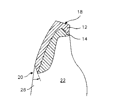
metal support structure 22 can be seen especially well in Fig. 3.
The layer 12 extends from the incisal area 18, following the
curvature of a natural tooth, down toward the root area and ends at
the transition portion 20 where it is pointed. In this transition area
the layer 12 is covered by the ceramic paste 26 whereby overlap
extends over an area of slightly less than 1 mm. The overlap angle
is 15° to 75° , preferably 20° to 45°, and more
preferred 30° .
Between the dental support structure 22 and the layer 12,
the layer14 of ceramic material that embodies the translucence of
dentin is provided. This layer 16 is slightly thicker at the transitional
portion 20 and extends to the lingual side across the support
structure 22.
For manufacturing the inventive dental replacement, the
metal support structure 22 is produced from a precious metal alloy
according to conventional criteria. Onto the metal crown a ceramic
opaquing agent is then applied and fired. It covers the metal color
_g_
Splanemann - 2657-! 1-18.996
CA 02287083 1999-10-21
and encloses the support structure at the top side and the lateral
surfaces completely. Subsequently, a ceramic material is applied
to the opaquing agent with conventional methods but is not yet fired.
A two-layer translucent pre-shaped ceramic part is then pressed
into the ceramic paste. This intermediate product is then positioned
on a silicone support and the ceramic part together with the ceramic
paste is then modeled and finished to a crown.
The crown is then removed from the silicone support and
fired. The fired crown is finemachined. Optionally, ceramic
corrections are applied before it is fired again. After completion of
the crown by grinding the final coating is applied and fired.
The crown has then a tooth-like translucence and, even
though the ceramic part is not completely embedded in the ceramic
paste, it is not visible to the eye.
In this context it is especially advantageous when the
transition portion is slanted in the aforementioned manner. By
properly selecting the transition angle, it can be prevented that light
refraction will make the ceramic part visible through the transition
portion of the fired ceramic paste.
Fig. 4 shows in which manner the ceramic parts are placed
onto the support structure 22. The ceramic parts 10 can clamp onto
-10-
Splanemann - 2657-11-18.996
CA 02287083 1999-10-21
the labial side of the support structure 22 so that with such a
clamping action form-locking and thus stable anchoring is provided.
-11-
Splanemann - 2657-1 f-18.996