Note: Descriptions are shown in the official language in which they were submitted.
CA 02287200 1999-10-22
WO 98/49394 PCT/FI98/00355
Method and equipment for attenuation of oscillation in a
paper machine or in a paper finishing device
The invention relates to a method and an apparatus for damping vibration in a
paper
machine or in a paper finishing device by means of a dynamic damper which com-
prises an additional weight suspended from a vibrating system by means of a
spring.
In paper machines and in paper finishing devices, vibrations constitute a
major
problem and, in present-day systems, when attempts are being made to achieve
ever
higher speeds, the vibration problems have become still more apparent than
before.
There are several possible sources of vibration in paper machines, and some of
the
most significant of them are rolls and cylinders, which comprise a very great
mass
revolving at a considerable speed. It is clear, of course, that when rolls are
manufac-
tured, attempts are being made to make their measurement precision as good as
possible and, in addition, they are balanced in order to eliminate the
vibrations.
However, present-day paper machines and paper finishing devices increasingly
employ rolls provided with a soft coating, which rolls in operation may form a
very
significant source of vibration. Such rolls are used, for example, in on-line
and off-
line calenders, coating machines, size presses, supercalenders and equivalent,
where
said roll provided with a soft coating forms a nip with another roll. A paper
web and
possibly a felt, wire or equivalent is passed through the nip. When in this
kind of
nip roll arrangement, the seam of the wire, felt or web, considerable
impurities or
something else causing a noticeable change in the thickness of the web
travelling
through the nip, passeslpass through the nip during running, the coating must
yield
elastically, with the result that the coating serves as a spring that excites
vibration.
For example, in a size press and in a coating device of the size press type,
the nip
is defined by means of two rolls such that one nip roll is mounted by means of
bearing housings directly on the frame structure of said device, while the
opposite
CA 02287200 1999-10-22
WO 98/49394 PCT/FI98/00355
2
roll is mounted at its bearing housings on loading arms that are attached by
means
of articulated joints to the frame structure of the machine. In that case, the
roll
mounted on the loading arms in particular begins to vibrate, in which
connection the .
coating of the soft-faced roll is deformed, with the result that the vibration
increases
and the roll begins to resonate. Until now, it has been necessary to take care
of and
to eliminate such vibrations so that, by changing the running speed of the
machine,
such a running speed has been sought that, at said running speed, the
vibration does
not grow any stronger but begins to be attenuated. The vibration problems have
prevented the use of certain speeds.
An object of the present invention is to provide a novel method and apparatus
for
damping vibrations that are being created such that the vibration can be
damped by
means of said method and apparatus without changing the running speed. The
invention is based on the use of a dynamic damper, and the method in
accordance
with the invention is mainly characterized in that, in the method, the spring
constant
of a spring of the dynamic damper and/or the mass of the dynamic damper is/are
changed by means of a control device in order to tune the natural frequency of
the
dynamic damper.
The apparatus in accordance with the invention is, in turn, characterized in
that the
apparatus comprises a control device which is arranged to change the spring
constant
of a spring of a dynamic damper andlor the mass of the dynamic damper in order
to
tune the natural frequency of the dynamic damper.
In an advantageous application of the invention, the vibration induced by
rolls that
are in nip contact is damped by means of the dynamic damper such that the
damper
is tuned to a frequency that is substantially equal to a multiple of the
rotational
frequency of the roll that is closest to the natural frequency of the
vibrating system.
The dynamic damper can also be tuned substantially directly to a frequency
that
corresponds to the problematic excitation frequency of a vibrating system.
r.. _...,. _ ~ . .... . . . .. ..... ~. . . . .. ..
CA 02287200 1999-10-22
WO 98/49394 PCT/FI98/00355
3
In one advantageous embodiment of the invention, in the method, the vibration
frequencies of a vibrating system are measured constantly by means of one or
more
vibration detectors, the measurement signals given by the vibration detector
are
amplified by means of an amplifier and fed into a vibration analyser which
identifies
the problematic excitation frequency and converts said problematic excitation
frequency into a control signal which is fed into a control device in order to
tune the
dynamic damper.
f
In one application of the invention, the spring of the dynamic damper is a rod
fixed
at one end thereof to a vibrating system, such as, for example, a bearing
housing of
a roll, in a substantially horizontal direction, on support of which rod an
additional
weight is mounted. In that case, the control device may be arranged to change
the
spring constant of the spring of the dynamic damper by changing the position
of the
additional weight on said rod.
Preferably, a locking means is fitted on the rod serving as the spring of the
damper
in order to lock the additional weight in place after the tuning frequency of
the
damper has been made as desired. The rod and the additional weight disposed on
the
rod may be provided with threads fitting each other so that the position of
the
additional weight on the rod may be adjusted by rotating said additional
weight on
the rod. In this kind of arrangement, the locking means is arranged to act in
the
axial direction of the rod and to produce an axial force acting on the
additional
weight in order to provide a frictional force necessary for locking between
the
matching threads on the rod and on the additional weight.
The locking means is preferably a pneumatically operated piston device which
is
fixed on the rod and which is telescopic in order to provide the necessary
stroke
length.
In one embodiment of the invention, the additional weight included in the
dynamic
damper comprises a container suspended from the spring and filled with a
liquid, the
amount of the liquid in said container being adjustable in order to regulate
the mass.
CA 02287200 1999-10-22
WO 98/49394 PCT/FI98/00355
4
In that connection, the control device is connected, for example, to a pump
and a
valve in order to regulate the amount of the liquid.
In one embodiment of the invention, the rod serving as the spring of the
dynamic
damper is made of memory metal. In this case, the natural frequency of the
damper
is arranged to be tuned by regulating the temperature of the rod made of a
memory
metal material by means of electric resistors or equivalent heaters. In this
kind of
embodiment of the invention, the additional weight can be attached to the rod
rigidly
and without a clearance, thereby providing a simpler construction in this
respect.
The invention provides a significant advantage over prior art especially in
that
vibration is damped by means of the method and the apparatus in accordance
with
the invention without changing the running speed of the machine. A substantial
and
significant advantage is also that the apparatus is very simple in its
construction and
in its mode of implementation and that it can be connected by very simple
operations
to existing structures for the purpose of damping vibrations. The further
advantages
and characteristic features of the invention will become apparent from the
following
detailed description of the invention.
In the following, the invention will be described by way of example with
reference
to the figures in the accompanying drawing.
Figure 1 schematically depicts a size press or a coating machine of the size
press
type to which the apparatus in accordance with the invention can be applied.
Figure 2 shows in schematic form one example of the apparatus in accordance
with
the invention.
Figure 3 is a fully schematic illustration of an advantageous mode of tuning a
damper.
__ . _..~._ ... , .. t . ... . . . _ ...
CA 02287200 1999-10-22
WO 98149394 PCT/FI98/00355
Figure 4 is an illustration corresponding to that of Fig. 2 of another example
of the
apparatus in accordance with the invention.
Figure 5 shows a further embodiment example of the apparatus.
5
Figure 6 shows an embodiment of the invention in which a special locking means
is
t
used for an additional weight of a damper.
Figures 7A and 7B are more detailed sectional views of the locking means shown
in
Fig. 6.
Figure 8 is finally a schematic view of a damper in which a memory metal
material
is used in the spring of the damper.
IS Fig. 1 has been included merely to illustrate one possible application of
the invention
and, thus, Fig. 1 shows a size press or equivalent, which is generally denoted
with
the reference numeral 10. The size press IO comprises a frame 14 on which a
first
size press roll 11 has been mounted directly by means of bearing housings 12.
In the
illustration of Fig. 1, said roll 11 is provided with a soft roll coating 13.
Loading
arms 16 have been mounted pivotally on the frame 14 of the size press by means
of
a pivot shaft 15 extending in the cross direction of the machine, on support
of which
loading arms a second roll 1 defining a nip N with the first roll 11 has been
mounted
at its bearing housings 2. For the purpose of providing a desired linear load
in the
nip N, the loading arms 16 are loaded by means of hydraulic cylinders I7, by
whose
means the nip N may also be opened. The reference signs I8 and 19 designate
coating units by whose means a coating material, such as size, pigment coating
material or equivalent is applied to the surface of the rolls. In a normal
way, a web
W is passed through the nip N.
When a seam or some other equivalent thicker pan travels through the nip N in
the
size press shown in Fig. 1, the coating 13 is deformed and it functions as a
spring,
with the result that the apparatus, in particular the roll 1 pivotally mounted
on the
CA 02287200 1999-10-22
WO 98/49394 PCT/FI98/00355
6
frame 14, begins to vibrate. Vibration deforms the roll coating 13 further,
where-
upon the vibration is intensified and the roll 1 is brought to a resonating
state. In
conventional arrangements, this has led to the fact that it has been necessary
to
change the running speed because it has not been possible to dampen the
vibration
otherwise. In the invention, however, the damping of vibration has been taken
care
of such that a dynamic damper that is automatically tuned in accordance with
the
invention is mounted on the bearing housing 2 of the vibrating roll 1, which
damper
is illustrated in more detail in Fig. 2 of the drawing.
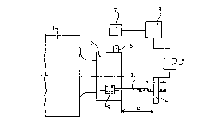
As shown in Fig. 2, the apparatus in accordance with the invention is in its
principle
very simple. In principle, the invention is constituted by a dynamic damper
known
per se and fitted on a vibrating system, i.e. in this case on the bearing
housing 2 of
the roll 1, which damper comprises a mass 4 suspended from the vibrating
system
2 by means of a spring 3. In the illustration of Fig. 2, the spring is a rod 3
rigidly
fitted on the bearing housing 2 by means of attachment members 5,. which rod
is
additionally provided with threads in the example of the figure. As the mass
serves
a weight 4 which is fitted on the rod 3 and which can be displaced by means of
the
threads in the longitudinal direction of the rod 3 such that the distance a of
the
weight 4 from the bearing housing 2 can be regulated. As already stated once
above,
the damper is thus a dynamic damper known per se. The basic equation of
dimensioning the dynamic damper is simply:
k/m = S22 where k = the spring constant of the spring, i.e. the rod 3 in this
case,
m = the mass of the weight 4, and SI = the angular velocity of the vibrating
system,
i.e. the bearing housing 2.
The effect of the dynamic damper is based in one advantageous embodiment of
the
invention on the fact that the natural frequency of said damper is tuned so as
to be
equal to the problematic excitation frequency. In this connection, it shall be
pointed
out that there may be several problematic excitation frequencies that differ
from one
another, but in one example which employs a coating machine of the size press
type
like the one shown in Fig. 1 there was a so-called lower problem frequency, in
which the motion of bearing housings was large, of the order of about 50 Hz.
Since
_~ . r . ? ... .._-. .._. __._ _ . ..
CA 02287200 1999-10-22
WO 98!49394 PCT/FI98/00355
7
the effective damping capacity of the dynamic damper is, however, limited to a
relatively narrow frequency band, it is clear that it must be possible to
regulate the
natural frequency of the damper. As it is commonly known that, for example, in
the
case shown in Fig. 2, the spring constant k of the rod 3 is inversely
proportional to
the power of three of the length of the rod, it is easy to regulate the
natural fre
quency of the damper by adjusting the distance a of the weight 4 from the
bearing
r
housing 2. When the natural frequency of the damper has been made equal to the
problematic excitation frequency by changing the distance a, the bearing
housing 2
ceases to vibrate and the weight 4 resting on support of the rod 3 begins to
vibrate,
respectively. This means that the arrangement formed by means of an additional
spring, i.e. the rod 3, and an additional weight, i.e. the weight 4, produces
a force
that is in an opposite phase and of equal magnitude to the excitation, whereby
the
vibration of the machine itself ceases.
As already stated above, a vibrating system or an equivalent object may have
several
problematic excitation frequencies because, depending on the system, it may
include
several devices which vibrate at different frequencies. For example, in the
size press
arrangement described previously, a significant source of vibration in the
system is
a vibrating roll. In this kind of example, the natural frequency of the
vibrating
system is not necessarily equal to a multiple of the rotational frequency of
the roll
inducing the vibration (in most instances this is not the case). In that
connection, a
very effective way of damping the vibrations of the system is that the damper,
for
example, a damper of the kind illustrated in Fig. 2, is tuned to a frequency
which
corresponds to a multiple of the rotational frequency of the roll that is
closest to the
natural frequency of the vibrating system. This multiple of the rotational
frequency
is thus used as the tuning frequency of the damper. This is illustrated fully
schemati-
cally in Fig. 3, which shows the relation between the natural frequency of a
vibrat-
ing system and multiples of the rotational frequency of a roll in a
frequency/amplitude coordinate system.
If the device in question were a device that is operated continuously at a
constant
speed, the vibrations could be brought under control merely by tuning the
natural
CA 02287200 1999-10-22
WO 98/49394 PCT/FI98/00355
8
frequency of the dynamic damper once to a correct level. However, in the paper
machine application, the running speeds and thus the vibration frequencies too
vary.
Consequently, it must be possible to regulate the dynamic damper fairly
precisely.
In the inventive arrangement shown in Fig. 2, adjustability is provided such
that the
bearing housing 2 whose vibration is desired to be damped is provided with a
vibration detector 6. The vibration detector 6 transmits a signal that is
amplified by
an amplifier 7 and passed further to a computer 8 serving as a vibration
analyser,
which filters and analyses the vibration frequencies and locates the
problematic
excitation frequency among the frequencies and converts it into a control
signal and
transmits said control signal to a control device 9 which moves the weight 4
on the
rod 3. The control device 9 is advantageously, for example, a stepping motor.
The
apparatus thus comprises a closed control circuit that constantly measures and
analyses vibrations and, based on this, regulates the natural frequency of the
dynamic damper.
The illustration of Fig. 4 corresponds to that of Fig. 2 so that this example
also uses
a vibration detector 6 that measures and identifies the vibrations of a
bearing housing
2 and transmits in accordance therewith a signal that is amplified by an
amplifier 7
and passed further to a vibration analyser 8. The vibration analyser 8
converts the
problematic excitation frequency it has found from the vibration frequencies
analysed
by it into a control signal and transmits it to a control device 9. The
dynamic
damper differs in this example from the one described previously such that the
damper comprises a spring 3a which is suspended from the bearing housing 2 and
from which a weight 4a is suspended whose mass can be changed. The spring 3a
itself is here constant in length. The weight 4a comprises, for example, as
shown in
Fig. 3, a container and a liquid in said container, the amount of said liquid
being
regulated by means of a pump 21 and a valve 22. The container is denoted with
the
reference sign 23. The control device 9 thus controls said pump 21 and valve
22
based on the control signal received by it in order to change the amount of
the liquid
in the container of the weight 4a.
..._T. _ .T..,._.~....~._..._ ~ ~. ..__ .,.... . . . . ..
CA 02287200 1999-10-22
WO 98149394 PCT/F198/00355
9
Fig. 5 shows a further embodiment of the invention which differs from the ones
described previously. In this embodiment, the spring 3b of the dynamic damper
comprises a rod that is mounted and attached to a bearing housing 2 in a way
corresponding to the illustration of Fig. 2. The weight 4b of the damper in
turn
corresponds in structure and in operation to the illustration of Fig. 3 so
that it
comprises a container and a liquid therein whose amount is regulated by means
of
a pump 21 and a valve 22. In the illustration of Fig. 5, the weight 4b is,
however,
suspended from the spring 3b such that its distance a from the bearing housing
2 can
be changed, for example, in a way corresponding to that shown in Fig. 2.
Accord-
ingly, both the distance a of the weight 4b from the bearing housing 2 and the
mass
of the weight 4b are regulated in the illustration of Fig. 5.
Fig. 6 shows an embodiment of the apparatus in accordance with the invention
which
is provided with a locking means 30 by whose means an additional weight 4 can
be
locked in place on the rod 3. In accordance with the embodiments described
above,
the rod 3 serving as the spring of the dynamic damper is attached to a
vibrating
system 2, such as, for example, a bearing housing by means of suitable
attachment
members 5. Fig. 6 further shows that the rod 3 is provided with threads 3'
and, in
a similar way, the additional weight is provided with threads matching said
threads
3' so that said additional weight may be moved on the rod 3 by rotating, i. e.
by
"screwing". Once the additional weight 4 has been brought to a correct place
on the
rod 3, it is locked in place by means of the locking means 30, which produces
a
force in the axial direction of the rod 3 in order to provide a frictional
force
necessary for locking between the rod 3 and the additional weight 4. As shown
in
Fig. 6, the locking means 30 is preferably attached to a free outer end of the
rod 3.
In Fig. 6, the locking means 30 is shown in a free position, in which
connection the
additional weight 4 can be moved by rotating on the rod 3. The structure and
operation of the locking means 30 is illustrated in more detail in schematic
sectional
views 7A and 7B.
Figs. 7A and 7B thus show the structure of the locking means 30 in more
detail.
Fig. 7A shows the locking means 30 in a free position corresponding to that of
Fig.
CA 02287200 1999-10-22
WO 98/49394 PCT/FI98/00355
6 and, correspondingly, in Fig. 7B, the locking means 30 is shown in a locking
position. The locking means 30 comprises a cylindrical casing 31 which
confines
within it a cavity that serves as a pressure space 32. A piston 33 is disposed
in this
pressure space 32 and sealed by means of seals against the inner wall of the
casing
5 31, said piston 33 being telescopic in the illustrated embodiment comprising
tele-
scopic parts 34. The piston 33 is attached to the rod 3, preferably in the
fashion
shown in Figs. 7A and 7B to the cuter end of the rod 3 immovably, and the
cylindrical casing 31 of the locking means 30 is thus fitted axially movably
on the
piston 33 and on the rod 3. The piston 33 divides the pressure space 32 in the
axial
10 direction in two parts, which are both provided with a connecting member
3b, 37 for
feeding in a pressure medium. Compressed air is preferably used as the
pressure
medium. Depending on the side of the piston 33 into which the pressure medium
is
passed, the locking means is brought either to the free position shown in Fig.
7A or
to the locking position shown in Fig. 7B. In the locking position, the casing
31 of
the locking means 30 has been displaced so that the end face 35 of the casing
facing
the additional weight 4 lies against said additional weight. The additional
weight 4
is shown in Figs. 7A and 7B only partially and schematically. When the
pressure
medium is conducted through the connecting member 37 into the pressure space
of
the locking means 30, an axial force needed for locking is produced, which
force
provides a frictional force of required magnitude between the thread 3' on the
rod
3 and the matching thread on the additional weight 4.
Finally, Fig. 8 shows fully schematically an alternative of the invention
where the
spring of the dynamic damper, i.e. the rod 3, is made of memory metal. The
coefficient of elasticity of memory metal is highly dependent on temperature.
In that
case, the natural frequency of the damper can be tuned to a right level by
regulating
the temperature of the rod 3. Regulation of temperature can be performed, for
example, by means of electric resistors or equivalent heaters. In this kind of
arrangement, an additional weight 4 can be attached to the rod 3 totally
rigidly and
without a clearance, for example, by welding. The structure may thus be made
fairly
simple. Regarding memory metals, it may be stated that they are alloys of
different
metals, of which an alloy of nickel and titanium may be mentioned as one
example.
.~_ __.. _ ... _...-..~,r ..... __.. ~ .." r. ..._ ..._ .....
CA 02287200 1999-10-22
WO 98/49394 PCT/FI98/00355
11
The properties of such an alloy may be regulated by introducing into it a
sufficient
amount of energy in the form of heating, with the result that the crystal
structure of
the metal alloy can be changed by this introduction of additional energy.
Memory
metal "remembers" the change which a certain heating operation brings about in
the
metal alloy.
s
It is also conceivable that the dynamic damper is applied in connection with
hollow
tubular rolls, for example, such that the dynamic damper- is disposed inside a
roll
tube. In this case, the dynamic damper might comprise two or more springs
which
are fixed to the inner surface of the roll tube while the weight of the
dynamic
damper is fixed on support of said springs. However, it may be considered that
it is
more difficult to provide adjustability for this kind of damper than in the
examples
described previously.
The invention has been described above in connection with a size press and a
coating
machine of the size press type in particular. However, problems of the similar
type
are also encountered, inter alia, in soft calenders and in supercalenders, and
the
apparatus in accordance with the invention may also be applied to them. The
problematic excitation frequencies differ. however, in these applications both
from
one another and from the arrangement shown in Fig. 1.
Above, the invention has been described by way of example with reference to
the
figures in the accompanying drawing. The invention is, however, not confined
to
relating only to the examples illustrated in the figures, but different
embodiments of
2~ the invention may vary within the scope of the inventive idea defined in
the accom-
panying claims.