Note: Descriptions are shown in the official language in which they were submitted.
CA 02287311 1999-10-19
WO 98/49500 PCT/US98/08390
- 1 -
TITLE
DUCTED FLOW HAIR DRYER
BACKGROUND OF THE INVENTION
Field of the Invention
The present invention relates to a hair dryer, and more
particularly, to a hand-held, ducted, axial-flow hair
dryer.
Description of Related Art
There are myriad different approaches to providing hair
dryers f or consumer use. The primary consideration for
such hair dryers is that they provide a flow heated of
heated air in a sufficient quantity to evaporate water
from the user's hair.
That goal is typically realized using a blower that
directs air over a heating device, such as a resistance
coil, and then to an outlet. Both axial-flow and
SUBSTITUTE SHEET (RULE 26)
CA 02287311 1999-10-19
WO 98/49500 PCT/US98/08390
- 2 -
centrifugal blowers have been used in known hair
dryers. See, for example, U.S. Patent No. 4,678,410
and German Patent DT 25 29 817, which disclose hair
dryers using axial-flow impellers, and U.S. Patent No.
3,943,329 and British Patent No. 1,519,652, which
disclose hair dryers using centrifugal-flow impellers.
Hand-held hair dryers have been in general use for many
years, and have found wide acceptance in the consumer
market. As the market has matured, commercial success
has demanded an increased ability to perform the hair
dryer's main task, that is, drying hair, while
providing a device that is quiet and safe to use.
To increase drying ability, one approach that will
obviously work is simply to increase the heat of the
air expelled from the unit. This approach has the
drawback of increasing the possibility of burns to the
user. There have been some attempts to ameliorate this
shortcoming by providing ducting around the dryer
outlet to inject ambient air into the exit air stream.
See, for example, U.S. Patent No. 3,284,611. U.S.
Patent No. 3,943,329 also discloses ducting provided
around the hair dryer outlet for safety reasons. Hair
dryers with this type of passive ducting do not have a
significantly increased amount of fluid flow for drying
a user's hair.
Therefore, to the extent that the use of such ducting
reduces the risk of injury to the user, it also reduces
the effectiveness of the exit air in drying the user's
hair. That is, it reduces the temperature of the air
directed against the user's hair without significantly
increasing the amount of air available to perform
drying.
SUBSTITUTE SHEET (RULE 26)
CA 02287311 1999-10-19
WO 98/49500 PCT/US98/08390
- 3 -
A ducting arrangement is also shown in U.S. Patent No.
5,317,815, in which a separate shell is attached to the
outlet of a hair dryer. The shell contains an impeller
vane that is rotated by the exit air from the hair
dryer, and is said to induce ambient air into the flow
through holes in the rear of the housing. Since the
outlet of the shell is larger than the hair dryer
outlet, the cross-sectional area of the air stream is
increased. However, those familiar with the principles
of fluid mechanics and the laws of physics will realize
that driving the impeller vane with the exit air from
the hair dryer imparts no additional energy to the air
stream. Therefore, while it may marginally increase
the amount of air flow, the increase is not significant
enough to offset the loss in drying effectiveness
caused by reducing the air temperature through
entraining ambient air in the flow.
Clearly, the amount of air flow can be increased simply
by increasing the speed of the rotating blower. That,
however, increases the amount of noise generated by the
hair dryer. According to well known principles, so-
called "dipole noise," Ndb, caused by rotating
components satisfies the relationship:
Ndb °~ ~6 ( 1
From equation (1) it can seen that dipole noise is
proportional to the sixth power of the rotational speed
w of the flow-generating components of a hair dryer.
Therefore, very small increases or decreases in the
rotational speed m will have a great effect on the
dipole noise generated by a hair dryer. Jet noise,
generated by the air stream mixing with the ambient air
at the dryer exit, also contributes to the noise
perceived by the hair dryer user.
SUBSTITUTE SHEET (RULE 26j
CA 02287311 1999-10-19
WO 98/49500 PCT/LJS98/08390
- 4 -
At the relatively low air flow velocities in a hair
dryer, dipole noise is the predominant noise source.
However, since jet noise scales with air flow velocity
to the eighth power (that is, Ua), jet noise can be
reduced perceptibly by reducing the velocity of the air
stream exiting the hair dryer. On the other hand, it
is likewise important that the drying ability of the
hair dryer not be compromised by reducing the air flow
velocity.
It has been recognized that hair dryer dipole noise can
be reduced by using an axial-flow impeller, with rotor
and stator elements. See, for example, U.S. Patent
4,678,410. And even a multi-stage axial-flow impeller,
with successive rotor and stator stages, has been used.
See, for example, German Patent No. DT 25 29 817.
However, those arrangements are used essentially to
provide air flow like that provided by more widely used
centrifugal blowers. They can produce the same air
flow at a lower rotational speed of the blower, but
they do not represent a different approach to solving
the problems inherent with hair dryers using
centrifugal blowers. That is, they can only produce
significantly greater air mass flow by increasing
rotational speed, and they can increase drying
effectiveness only by increasing the heater (and
therefore air) temperature.
What is required to move to the next generation hair
dryer is a configuration that will provide optimum air
mass flow and permit reduced air flow velocities, and
also enable the efficient introduction of an
appropriate amount of heat, while reducing noise levels
to the barest minimum.
SUBSTITUTE SHEET (RULE 26)
CA 02287311 1999-10-19
WO 98/49500 PCT/US98/08390
- 5 -
BRIEF DESCRIPTION OF THE INVENTION
It is an object of the invention to achieve those goals
by overcoming the limitations inherent in previous hair
dryer configurations and approaches.
According to one aspect of the present invention, an
axial flow hair dryer comprises a housing forming an
air flow passage having an air inlet and an air outlet,
a first axial flow impeller disposed in the housing for
generating air flow from the inlet to the outlet of the
housing, an outer duct having an air inlet and an air
outlet, the outer duct being secured to the housing
with the air outlet of the housing disposed to form an
annular air intake between the housing and the outer
duct, a second axial flow impeller disposed in the
outer duct for generating air flow through the annular
air intake to the outlet of the outer duct, driving
means for supplying motive force to the first axial
flow impeller and second axial flow impeller, and
heating means for heating the air flowing through the
hair dryer.
In its more detailed aspects, an axial flow hair dryer
in accordance with the present invention comprises a
housing forming an air flow passage having an axis and
an air inlet and an air outlet, which housing includes
a handle depending therefrom, an integrally molded
first fan stage including a first axial flow impeller
disposed in the housing for generating air flow from
the inlet to the outlet of the housing generally along
the axis thereof, an integrally molded first stator
stage disposed in the housing downstream of the first
fan stage and having a plurality of radially extending,
flat stator vanes connected to a hub at the axis of the
housing and rigidly secured to said housing, an outer
duct forming an air flow passage having an axis
SUBSTITUTE SHEET (RULE 26)
CA 02287311 1999-10-19
WO 98/49500 PCT/US98/08390
- 6 -
substantially coincident with the axis of the housing
and having an air inlet and an air outlet, the outer
duct being rigidly secured to the housing with the air
outlet of the housing disposed within the outer duct to
form an annular air intake between the housing and the
outer duct, an integrally molded second fan stage
including a second axial flow impeller disposed in the
outer duct for generating air flow through the annular
air intake to the outlet of the outer duct, the second
axial flow impeller including a plurality of inner
blades and a plurality of outer blades separated by an
annular shroud that forms an extension of the air flow
passage formed by the housing, an integrally molded
second stator stage disposed in the outer duct
downstream of the second fan stage and including a
plurality of radially extending, flat inner vanes
connected to a hub at the axis of the outer duct and to
an annular shroud that forms an extension of the
extended air flow passage formed by the annular shroud
of the second fan stage and a plurality of radially
extending, flat outer vanes connected to the annular
shroud, wherein the outer vanes are rigidly secured to
the outer duct, a motor mounted inside the handle with
a vibration-absorbing material interposed between the
motor and the handle, a drive shaft mounted for
rotation in the hub of the first stator stage and the
hub of the second stator stage, the first fan stage and
the second stator stage being mounted to the drive
shaft for rotation therewith, a flex shaft for
supplying motive force from the motor to the drive
shaft, and resistance heating means for heating air
flowing through the air dryer.
SUBSTITUTE SHEET (RULE 26)
CA 02287311 1999-10-19
WO 98/49500 PCT/US98/08390
BRIEF DESCRIPTION OF THE DRAWINGS
The objects of the invention will be better understood
from the detailed description of its preferred
embodiments which follows below, when taken in
conjunction with the accompanying drawings, in which
like numerals refer to like features throughout. The
following is a brief identification of the drawing
figures used in the accompanying detailed description.
FIGURE 1 is an overall depiction of a preferred
embodiment of a hair dryer comprising the present
invention.
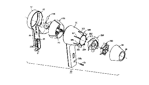
FIGURE 2 is an exploded perspective view of the hair
dryer shown in FIGURE 1.
FIGURE 3 is a cross-sectional view taken along the axis
of the hair dryer depicted in FIGURE 1.
FIGURE 4 is a detailed view of the first fan stage 100
of the hair dryer depicted in FIGURE 2, wherein FIGURE
4A is a perspective view and FIGURE 4B is a front view
of the first fan stage.
FIGURE 5 is a detailed view of the first stator stage
150 of the hair dryer depicted in FIGURE 2, wherein
FIGURE 5A is a front view of the first stator stage and
FIGURE 5B is a sectional view taken along line 5B-5B of
FIGURE 5A.
FIGURE 6 is a detailed view of the second fan stage 20
of the hair dryer depicted in FIGURE 2, wherein FIGURE
6A is a perspective view and FIGURE 6B is a rear view
of the second fan stage.
SU9STITUTE SHEET (RULE 26)
CA 02287311 1999-10-19
WO 98149500 PCT/IJS98/08390
_ g _
FIGURE 7 is a detailed view of the second stator stage
250 of the hair dryer depicted in FIGURE 2, wherein
FIGURE 7A is a rear view of the second stator stage and
FIGURE 7B is a sectional view taken along line 7B-7B of
FIGURE 7A.
DETAILED DESCRIPTION OF PREFERRED EMBODIMENTS
Referring to FIGURES 1 to 3, a hair dryer 10 according
to an embodiment of the invention includes a main
housing 20 with an air inlet 22. The hair dryer 10
also includes an outer air duct 24 that overlaps a
portion of the main housing 20 to form an annular air
intake 26 between the outside of the main housing 20
and the inside of the outer duct 24. That is, in the
present embodiment the outlet 27 of the main housing 20
is disposed within the outer duct 24. The outer duct
24 terminates in an air outlet 28. The main housing 20
and outer duct 24 incorporate an axial-flow impeller
system described in more detail below.
The main housing 20 is provided in two parts, a forward
housing 30 and a rear cover 32. Both the forward
housing 30 and rear housing 32 are integral units
injection molded of plastic, and they mate as shown in
FIGURES 1 and 3 to form the main housing 20 and a
hollow handle 34 depending integrally from the main
housing 20.
FIGURE 3 illustrates how the forward housing 30 and
rear cover 32 mate to form the main housing 20 and the
integral handle 34 depending from the main housing 20.
The forward housing 30 has a thinned portion forming a
flange 30a around its open rear face, and the rear
cover 32 has a undercut portion 32a inside the
periphery of its open front face. The undercut portion
32a fits over the external flange 30a on the forward
SUBSTITUTE SHEET (RULE 26)
CA 02287311 1999-10-19
WO 98!49500 PCT/US98/08390
- 9 -
housing 30, and the rear cover 32 and forward housing
30 are secured together by a screw 35 passed through a
counterbore 30b on the handle portion of the forward
housing 30 and threaded into a boss 32b on the handle
portion of the rear cover 32.
The cooperating flange 30a and undercut portion 32a
positively locate the forward housing 30 and rear cover
32 relative to each other. The screw 35 removably
secures the forward housing and rear cover together.
The flange 30a and undercut portion 32a permit the
forward housing 30 and rear cover 32 to be secured
together with their outer surfaces flush with each
other.
A motor 36 is disposed in the handle 34. This is an
important feature of the present invention, because it
allows the motor to be isolated acoustically from the
remaining structure of the hair dryer. In the
embodiment illustrated in FIGURE 3 the motor 36 is
mounted to a motor bracket 37 made of suitable sheet
metal bent into the shape depicted. The motor bracket
is secured to the handle portion 34 of the forward
housing 30 using countersunk screws 37a threaded into
the bracket 37. Alternatively, the screws could be
threaded into lock nuts on the other side of the
bracket 37. The motor 36 is secured to the bracket 37
with a shock absorber 38 interposed between the bracket
37 and the motor 36. The shock absorber 38 can be an
appropriate rubber compound or any other suitable
vibration-absorbing material. Bolts 38a pass through
the bracket 37 and are threaded into the motor housing
to hold the motor onto the bracket 37 with the shock
absorber 38 sandwiched between them. Of course, an
alternative fastening technique can also be used, as
mentioned above in connection with the screws 37a.
Instead of using a bracket which is isolated from the
SUBSTITUTE SHEET (RULE 26)
CA 02287311 1999-10-19
WO 98/49500 PCT/US98/08390
- 10 -
motor 36 by a shock absorber, it would also be possible
to mount the motor by enveloping it completely in a
vibration-absorbing material such as polyurethane foam
capable of holding the motor in place.
As discussed in more detail below, the unique fluid
flow properties of a hair dryer according to the
present invention make it feasible to employ an axial-
flow impeller system with the drive motor off-axis.
Therefore, the noise reduction made possible by the
fluid flow properties of the hair dryer can be enhanced
further still by placing the motor in a location where
a suitable mounting arrangement, such as one of those
discussed above, can be employed to isolate the user
from the noise and vibration inherent in operation of
the motor.
The handle 34 also contains conventional circuitry for
supplying power to the motor 36 as well as to
resistive heating elements, discussed in detail below.
An ON-OFF switch 39 is conveniently placed on the
handle. This switch can be a toggle switch as shown,
or a slide switch, or assume other forms, but in any
case it will typically have multiple positions
corresponding to multiple power settings (that is,
blower speed/heating current combinations) for
providing maximum convenience of use to the operator.
The circuitry required for providing multiple power
settings to that end will be conventional in design and
within the skill of those working in this field.
Accordingly, a detailed description of same is not
included here.
The multi-stage, ducted, axial-flow structure of the
hair dryer of the present invention includes multiple
fan and stator stages in the ducts formed by the main
housing 20 and outer air duct 24. These stages are the
SUBSTITUTE SHEET (RULE 26)
CA 02287311 1999-10-19
WO 98/49500 PCT/US98/08390
- 11 -
first fan stage 100, the first stator stage 150, the
second fan stage 200, the second stator stage 250 and a
duct stator stage 300. The fan stages 100 and 200 are
mounted to an axial drive shaft 40 that is supported
for rotation by the stator stages 150 and 250 in a
manner discussed in detail below. A flex shaft 42
constitutes a drive mechanism that provides motive
power to the drive shaft 40 from the motor 36.
FIGURE 2 shows the duct stator stage 300 in detail. It
comprises seven vanes 301, 302, 303, 304, 305, 306 and
307, molded integrally with the forward housing 30. As
FIGURE 3 illustrates, the large-diameter inlet end of
the outer duct 24 fits over the vanes 301-307 and is
suitably secured thereto to mount the outer duct on the
forward housing. The outer duct 24 is a plastic,
injection-molded, one-piece part. It is secured to the
vanes 301-307 by heat welding or with an adhesive or
both. Of course, other materials and attachment
techniques can be used.
FIGURE 4 shows the first fan stage 100 in detail. The
first fan stage comprises an axial flow impeller having
five blades 104, 105, 106, 107 and 108 attached to a
hub 110. The fan blades 104-108 have the shape shown
in FIGURE 4. The first fan stage may also conveniently
be an injection-molded, one-piece, plastic part.
The first stator stage 150, shown in detail in FIGURE
5, is located just downstream of the first fan stage
100. The first stator stage includes three vanes 152,
153 and 154. The vanes 152-154 extend radially between
a hub 156 and an outer envelope 158. The entire first
stator stage 150 is integrally molded from a suitable
material. The contour of the outer envelope 158
generally matches the contour of the forward housing 30
of the main housing 20. The outer envelope 158
SUBSTITUTE SHEET (RULE 26)
CA 02287311 1999-10-19
WO 98/49500 PCT/US98/08390
- 12 -
includes axially extending ridges 160, 161 and 162 that
fit into cooperating axial grooves 164 (see FIGURE 3)
in the forward housing 30 to positively locate the
first stator stage angularly in the forward housing 30.
Such a locating system is preferred because the forward
housing 30 is not completely symmetrical about its axis
at the location where the first stator stage is
mounted. That is, the inclusion of the handle 34 as
part of the main housing causes the bottom portion of
the main housing to be non-cylindrical where it
smoothly transitions into the portion comprising the
handle. As a result, the outer envelope 158 does not
contact the inner surface of the housing 30 around the
envelope's entire periphery.
Accordingly, the two vanes 153 and 154 are spaced 150°
apart, symmetrical about a diameter of the stator 150
that includes the first vane 152. In that manner, the
vanes 152-154, all of which serve the structural
purpose of supporting the dryer's drive shaft in a
manner discussed below, are positively supported by the
housing 30.
FIGURE 6 shows the second fan stage 200, which is
provided just beyond the end of the housing 30. The
second fan stage includes five evenly spaced inner
blades 2021, 2031, 2041, 2051 and 2061 extending
outwardly from a hub 207, and five evenly spaced outer
blades 2020, 2030, 2040, 205o and 2060, each of which
extends outwardly as a continuation of the
corresponding inner blade of the same number.
Separating the inner and outer rotor blades is an
annular shroud 208 that forms an extension of the
housing 30. That is, except for the axial clearance
between the end of the housing 30 and the shroud 208,
the latter forms a part of the inner air duct provided
SUBSTITUTE SHEET (RULE 26)
CA 02287311 1999-10-19
WO 98/49500 PCT/US98/08390
- 13 -
by the forward housing 30. The second fan stage 200 is
injection molded in one piece using plastic.
FIGURE 7 shows the second stator stage 250. It
comprises four evenly spaced inner vanes 252, 253, 254
and 255, and six evenly spaced outer vanes 256, 257,
258, 259, 260 and 261. The inner vanes 256-261 extend
between a central hub 262 and terminate at an annular
shroud 264 which forms an extension of the annular
shroud 208 of the second fan stage 200. The outer
vanes 256-261 extend radially outwardly from the shroud
264. It is integrally molded by injection molding.
The hair dryer of the present invention is typically
assembled in the following manner. The outer envelope
158 of the first stator stage 150 is introduced into
the forward housing 30 through its open rear face. The
axial ridges 160-162 are positioned for insertion into
the cooperating grooves in the inner surface of the
forward housing 30. The outer envelope 158 is secured
to the inner surface of the forward housing in any
suitable manner, preferably by heat welding and using
an adhesive. It is important that the first stator
stage 150 be firmly attached to the forward housing 30,
because the hub 156 forms the rear bearing for
supporting the axial drive shaft 40 of the hair dryer.
Prior to assembling the first stator stage into the
front housing, the vanes 152-154 are each wrapped with
resistance heating coils 70 of Nichrome° alloy wires,
as shown in FIGURE 3. These wires are connected in a
suitable fashion to the power circuitry in the handle
34 once the first stator stage 150 is assembled into
the forward housing 30.
The second stator stage 250 is securely attached within
the outer duct 24 by heat welding and/or using an
SUBSTITUTE SHEET (RULE 26)
CA 02287311 1999-10-19
WO 98/49500 PCT/US98/08390
- 14 -
adhesive to firmly secure the outer vanes 256-261 to
the inside wall of the outer duct at the proper axia_1
location. Again, it is important that the second
stator stage be securely and rigidly attached to the
outer duct so that a rigid structure is formed, because
the hub 262 provides a bearing for the drive shaft 40
in a manner to be described.
The drive shaft 40, onto which the hub 207 of the
second fan stage 200 has been secured in a suitable
fashion, is inserted through the hub 156 of the first
stator stage 150 and held in place while the outer duct
is positioned on the vanes 301-307 forming the duct
stator stage.
1S
The end of the drive shaft 40 is introduced through the
central opening in the hub 262 of the second stator
stage and the outer duct is secured to the vanes 301-
307 by heat welding and/or using an adhesive. In this
manner, the two stator stages 150 and 250, the forward
housing 30 and the outer duct 24 form a rigid,
permanent assembly supporting the drive shaft 40 for
rotation in the hubs 156 and 262.
The hubs each include a suitable bearing surface, such
as a bronze insert or a coating of Teflon° polymer, to
reduce friction on the shaft 40 and the bearing
surface. Cooperating sleeves 44 and 46 of Teflon°
polymer also may be used. If so, they are secured
rigidly to the drive shaft and the respective hubs 110
and 207 of the first and second fan stages, so that
rotational motive force applied to the drive shaft
causes rotation of the fan stages. The drive shaft is
also secured against axial movement in a suitable
manner, such as by ring clips (not shown) fitting in
circumferential grooves in the shaft.
SUBSTITUTE SHEET (RULE 26)
CA 02287311 1999-10-19
WO 98/49500 PCT/US98/08390
- 15 -
The first fan stage is then secured to an end of the
drive shaft 40 extending beyond the first stator stage
150. The flex shaft 42 is secured in a suitable manner
between the motor 36 and the drive shaft 40, and the
rear cover 32 is attached to the front housing to
complete the hair dryer 10.
It may be noted that the second stator stage 250 can be
used to provide additional heat capacity by wrapping
some or all of the stator vanes with resistive heating
coils in the same manner as the vanes 152-154 of the
first stator stage are wrapped with Nichrome° alloy
wires (see FIGURE 3). In that event, the second stator
stage is made from a suitable material, and the wires
are connected to the power circuitry in an appropriate
fashion to provide operation as desired. For example,
at maximum air flow all heating coils on both stator
stages could be activated to provide maximum drying
ability. Suitable combinations of air mass-flow and
heat input can be developed by those skilled in the art
without a more detailed description here.
The air intake 22 at the rear cover 32 and the air
outlet 28 at the end of the outer duct 24 may require
suitable protection. This will typically be provided
in the form of having the air inlet formed of radially
extending slots (not shown) too small for the passage
of the user's fingers, or a metal screen, or both. The
same will be true of the air outlet. These safety
features are largely governed by industry standards,
and the hair dryer of the present invention can easily
accommodate any such safety requirements.
An advantage of the present invention is that the air
flow characteristics of the hair dryer can be tailored
to maximize mass flow of the dryer's air throughput
while minimizing the speed of revolution of its
SUBSTffUTE SHEET (RULE 26)
CA 02287311 1999-10-19
WO 98/49500 PCT/US98/08390
- 16 -
rotating parts. The use of multiple rotor stages and
providing the annular air intake 26 significantly
increases the mass flow rate of air through the hair
dryer at a given rotational speed. For example,
commercial hair dryers today typically run at speeds of
about 10,000 rpm, and sometimes even higher. The
present invention can duplicate the same mass flow rate
at rotational speeds in the order of one-half of that
of current commercial hair dryers.
The mathematical techniques for providing the desired
flow characteristics of a hair dryer with the
configuration shown are well known to those skilled in
the art. The shape of the housing 20 and outer duct
24, the axial length of the annular duct 68 between
them and the variation in area of that annular duct in
the axial direction, the number of stator and rotor
stages, and the shapes and number of blades in each,
are all capable of being chosen by those skilled in the
art using known principles of aerodynamics and fluid
mechanics.
An example of how the configuration of the various
parts can be determined will be given for illustrative
purposes. It should be understood that other
configurations are possible within the scope of the
invention.
A typical starting point will be the rotating speed w
of the drive shaft 40 and thus of the two fan stages
100 and 200. It may be desired to minimize the noise
generated by the hair dryer by choosing w~, = 5000 rpm
(revolutions per minute). The heat output is expressed
as follows:
q = mC~T ( 2 )
SUBSTITUTE SHEET (RULE 26)
CA 02287311 1999-10-19
WO 98/49500 PCT/US98/08390
- 17 -
where q is the heat output of the dryer, m is the
mass flow of air through the dryer, Cp is the heat
capacity of air, and DT is the temperature increase
over ambient of the air exiting the hair dryer. CP is a
known property of air, and the maximum exit temperature
of the air is set by industry standards as embodied in
specifications published by Underwriters Laboratories,
Inc. A typical maximum heat output q might be 2000
watts, which using equation (2) yields a required air
mass flow m - 0.03 m3/sec for an exit temperature of
about 70 °C.
Using known equations for axial-flow fan design, the
configuration of each fan stage can be determined. Of
course, that presupposes that the number of fan stages
has been chosen. In the embodiment of the invention
shown herein, a hair dryer with two fan stages is
depicted. To avoid complications, certain design
choices can also be incorporated into the fan stages.
For example, the blades can be made essentially flat
(that is, with minimum camber). It is important to
realize that the first and second fan stages must be
designed in concert. For example, it has been found
that the blade incidence-angle in the second fan stage
generally should be greater than the blade incidence-
angle in the first fan stage. An ideal configuration
will yield a uniform velocity profile in the radial
direction at any given axial location in the air dryer.
As for the stator stages, they are provided by flat
vanes in the present embodiment, although the invention
is not limited to the use of flat stator vanes. As is
well known, the stators straighten, or "deswirl," the
flow exiting the fans, to recover the kinetic energy in
the flow. That is, after exiting a fan stage, the air
flow has a complex velocity distribution that detracts
from its kinetic energy in the axial direction. The
SUBSTITUTE SHEET (RULE 26)
CA 02287311 1999-10-19
WO 98/49500 PCT/US98/08390
- 18 -
stator stages redirect the flow to recover this kinetic
energy. The vanes 301-307 of the duct stator stage 300
help to direct the flow into the outer blades 2020-2060
of the second fan stage at an optimum angle of attack.
The air flow envelope of the ducts is also chosen
according to known engineering design principles. The
exit velocity of the air flow is an important parameter
in that regard. Those skilled in the art will
recognize that there are certain practical limits that
consumers place on exit velocity magnitudes, as well as
there being engineering reasons to have an exit
velocity of a certain minimum value.
However, once the total mass flow through the hair
dryer is determined, the required dimensions of the
ducts can be determined knowing the desired exit
velocity. In the embodiment depicted herein, the main
housing 30 has a cylindrical inlet portion that extends
to the downstream end of the first fan stage 100.
Then, the flow envelope is a cubic function, that is,
d = f(x'~3), where d is the diameter of the main housing
and x is the axial distance along the housing. The
outer duct 24 is also configured as a cubic function of
the axial distance along the duct. This profile is
chosen empirically to inhibit flow separation from the
internal duct walls.
It is preferable that the number of stator vanes in
each stage be different from the number of fan blades.
If the number were equal, there would be a periodic
situation in which the ducts are subject to minimum
blockage (when the fan blades are in the same angular
position as the stator vanes), and maximum blockage
(when the fan blades are equally spaced angularly
between the stator vanes). This effect is experienced
SUBSTITUTE SHEET (RULE 26)
CA 02287311 1999-10-19
WO 98/49500 PCT/US98/08390
- 19 -
by the user as a source of periodic noise. Using
unequal numbers of stator vanes and fan blades
minimizes this effect. It should also be mentioned
that the present invention is not limited to the use of
a particular number of fan blades or stator vanes in a
particular stage, or to the number of fan and stator
stages shown.
As noted above, the air flowing through the hair dryer
is heated by resistance coils 70 wound around the vanes
152-154 of the ffirst stator stage 150. The resistance
coils 70 are in an actuation circuit that permits them
to be energized for different levels of heat
generation. For example, the resistance coils 70 are
energized to a lower temperature to provide a low-heat
setting in which the air is heated to a moderate
temperature, and to a higher temperature to provide a
high-heat setting. In the low-heat setting the fans
are rotated at a low speed and in the high-heat setting
they are rotated at a higher speed.
Wrapping the resistance coils around the stator vanes
provides some unique advantages. It causes intimate
contact between the air flow and the heating coils
because the heating coils induce turbulence in the flow
and thus increase mixing of the air flow passing over
the vanes, thereby promoting more efficient heat
transfer from the coils to the air. At the same time,
the resistance coils do not significantly decrease the
flow area and they do not have a deleterious effect on
the operation of the stator vanes in deswirling the
flow. This enhanced mixing effect enables the heating
coils to be concentrated in a smaller area in the flow
stream, thus reducing the pressure drop across the
heating coils.
SUBSTITUTE SHEET (RULE 26)
CA 02287311 1999-10-19
WO 98/49500 _ PCT/US98/08390
- 20 - -
It is not necessary to coil the wires before they are
wrapped around the stator vanes. For example, the
wires can be made of a flat cross-section and wound
around the stator vanes in a fashion similar to that
shown for the coiled wires depicted herein_ Such an
arrangement also serves to "trip" the flow over the
vanes, thus inducing turbulence and enhancing mixing.
This arrangement makes the air flow through the hair
dryer more efficient because it will reduce even
further the pressure drop caused by having the coils in
the air flow.
If desired, however, one or more additional resistance
coils can be placed in the path of the flow. One way
of introducing an additional heating coil would be to
provide a grid in the main housing 20 downstream of the
first stator stage 150. This grid could be rigidly
attached to the housing to increase its structural
rigidity.
An important feature of the present invention is the
placement of the motor 36 in the handle 34. In any
hair dryer, the motor contributes to the total noise
generated when operating the hair dryer. In the
present invention, the motor 30 is placed in the handle
where it can be isolated from the structure of the hair
dryer, as discussed above, thus reducing the overall
noise generated by the hair dryer. In prior axial flow
air dryers, the motor typically forms a part of the
rotor axis, as in U.S. Patent No. 4,678,410 and German
Patent No. DT 25 29 817. This reduces the space
available for air flow and makes noise shielding more
difficult.
In the present invention, the use of ducted, axial air
flow with multiple rotor stages reduces the rotational
speed and torque that the motor must deliver.
SUBSTITUTE SHEE? (RULE 26~
CA 02287311 1999-10-19
WO 98/49500 PCT/US98/08390
- 21 -
Therefore, the motor can be located remotely in
relation to the rotor axis and a drive train mechanism
used to transient motive power to the rotor axis.
In the embodiment shown, the drive train comprises the
flex shaft 42. This flex shaft is a double-wound
spring, which has good resistance to torsional
deformation but low bending resistance. Those skilled
in the art will recognize that this flex shaft will
have a natural frequency of vibration depending on its
physical properties, such as Young's modulus and cross-
sectional area. However, because of the lowered
rotational speeds of the hair dryer of the present
invention, it is possible to provide a flex shaft with
a natural frequency much higher than the maximum
rotational speed it will encounter in operation.
Accordingly, the motor 36 can be placed in the handle
34 and acoustically isolated from its mounting
structure.
It will be appreciated that other drive train
arrangements can be substituted for that described
above. For example, the fan stages need not be mounted
on the same drive shaft or rotate at the same speed or
direction. Moreover, a transmission mechanism other
than the flex shaft 42, such as a belt-and-pulley
system, can be used.
While preferred embodiments of the invention have been
depicted and described, it will be understood that
various modifications and changes can be made other
than those specifically mentioned above without
departing from the spirit and scope of the invention,
which is defined solely by the claims that follow.
. ur,.~~~.
SUBSTITUTE SHEET (RULE 26)