Note: Descriptions are shown in the official language in which they were submitted.
CA 02287625 1999-10-22
METHOD OF PATCHING DOWNHOLE CASING
BACKGROUND OF THE INVENTION
1. Field of the Invention
The present invention relates to a method for sealing areas in
a well bore, and more particularly, by not by way of limitation, to
an improved method for inserting a tubular viscoelastic material
into a casing affixed within a well bore for repairing breaches in
the casing.
2. Description of Related Art
As the drilling of an oil or gas well progresses, the well
bore is lined with a casing that is secured in place by a cement
slurry injected between the exterior of the casing and the well
bore. The casing functions to provide a permanent well bore of
known diameter through which drilling, production or injection
operations may be conducted. The casing also provides the
structure for attaching surface equipment required to control and
produce fluids from the well bore or for injecting fluids therein.
In addition, the casing prevents the migration of fluids between
subterranean formations through the well bore, i.e., the intrusion
1
CA 02287625 1999-10-22
of water into oil or gas formations or the pollution of fresh water
by oil, gas or salt water.
The mechanical integrity of the casing and the ability of the
casing to isolate subterranean formations is closely regulated.
Casing which has been cemented in a well bore is required to pass
a mechanical integrity test to assure that no breaches in the
casing occur. If the casing fails the mechanical integrity test,
the casing must be repaired. Mechanical integrity failure can
result from various means, such as corrosion, old perforations, or
other breaches in the casing including joint leaks, split casing or
parted casing.
Mechanical integrity failures are normally repaired by either
replacing the defective casing, cementing a new casing inside the
old casing, or injecting cement into the breach of the casing which
is commonly known as "squeeze cementing". Replacement of defective
casing is often not feasible because of the initial completion
method used and the risk in damaging additional casing due to
stress imparted on the casing during such an operation. Because
the operation of inserting a new casing inside the old casing is
expensive, this option may not be economically feasible.
Additionally, squeeze cementing is not always economically
feasible, and is inappropriate for certain types of subterranean
formations. Furthermore, when squeeze cementing is utilized,
satisfactory results are not always obtained. Finally, each of
these remedies are costly in terms of the amount of time required
2
CA 02287625 1999-10-22
for each operation, and therefore, the amount of time that the well
is out of service.
To avoid the expense and time associated with the above-
mentioned remedies, sealing apparatuses employing retrievable
packers have been utilized for sealing and isolating casing at the
point of the mechanical integrity failure. However, when employing
such sealing apparatus, problems have been encountered. For
example, the annular flow of fluids about a tubing string which
extends through the sealing apparatus is often restricted, thus
producing a hydraulic breaking effect as the apparatus is inserted
into the well bore. Further, the annular flow may be restricted
during mechanical integrity testing which requires an annulus
between the tubing string and the casing. Lastly, the sealing
apparatus is often ineffective because the resilient sealing
elements become worn or deteriorate due to rough or cement-coated
interior casing walls when the sealing apparatus is inserted into
the well bore.
A method of lining the casing with a continuous string of
tubular viscoelastic material has also previously been proposed.
This method is disclosed in U.S. Patent No. 5,454,419, issued to
Jack Vloedman, the present inventor. The method disclosed in the
Vloedman '419 patent utilizes a continuous, seamless viscoelastic
tubular liner wound on a portable spool. The liner, which has an
outer diameter greater than the inner diameter of the casing, is
reeled off the spool and through a roller reduction unit to reduce
the diameter of the liner so that the liner can be injected into
3
CA 02287625 1999-10-22
the casing. A weight system connected to the bottom end of the
liner maintains the reduced liner in tension so that the liner
remains in its reduced state until the liner is positioned at a
desired depth. After the liner is run to such depth, the weights
are removed thereby allowing the reduced liner to rebound and form
a fluid tight seal with the casing and effectively sealing any
breaches in the casing.
While the method disclosed in the Vloedman '419 patent has
successfully met the need for repairing breaches in casing in an
effective and time efficient manner, several inefficiencies-have
nevertheless been encountered, particularly in circumstances when
only a selected segment of the casing is in need of repair. That
is, if only a relatively short section of approximately 100 to 2000
feet of casing is in need of repair and this section is located
several thousand feet below the surface, for example, it is more
cost effective if the casing does not have to be lined entirely
from the surface to the pertinent section. In addition,
viscoelastic tubing has less tensile strength than conventional
steel tubing. As such, in attempting to line the casing at depths
below about 5,000 feet, the weight of the weight system coupled
with the weight of the lining run into the casing can cause the
lining to fatigue or even fail.
To this end, a need exists for an improved method for patching
selected sections of casing with segments of viscoelastic tubing
having a length less than the distance extending between the
surface and a preselected depth to repair breaches therein which is
4
CA 02287625 2004-02-03
durable and effective, while remaining inexpensive and time
efficient. It is to such an improved method that the
present invention is directed.
BRIEF SUMMARY OF THE INVENTION
The present invention is directed to a method for
lining a portion of a casing affixed within a well bore a
distance below an upper end of the well bore with a
viscoelastic pipe having an upper end, a lower end, and an
outer diameter greater than the inner diameter of the
casing. The outer diameter of the pipe is reduced so that
the outer diameter of the pipe is less than the inner
diameter of the casing. The reduced pipe is then lowered
IS into the casing to a predetermined depth where the upper
end of the reduced pipe is positioned a distance below the
upper end of the well bore. The reduced pipe is then
allowed to expand against the internal wall of the casing.
According to this invention a method, for lining a
portion of a casing affixed within a well-bore a distance
below an upper end of the well-bore, comprises providing a
viscoelastic pipe having an upper end, a lower end and an
outer diameter greater than the inner diameter of the
casing, and reducing the outer diameter of the pipe so that
the outer diameter of the pipe is less than the inner
diameter of the casing. The step of reducing the outer
diameter of the pipe comprises: disposing an upper
connector assembly in the upper end of the viscoelastic
pipe, the upper connector assembly having an outer diameter
less than the inner diameter of the viscoelastic pipe
connecting a guide shoe to the upper end of the
viscoelastic pipe, the guide shoe having an inner diameter
5
CA 02287625 2004-02-03
less than the inner diameter of the viscoelastic pipe such
that a support shoulder is formed by the guide shoe;
linking the upper connector assembly to a carrier section
of viscoelastic pipe; passing the viscoelastic pipe through
a roller-reduction unit comprising a plurality of banks of
rollers, the banks of rollers cooperating to form a
substantially frusto-conically shaped passageway such that
the outer diameter of the viscoelastic pipe is gradually
reduced as the viscoelastic pipe is passed therethrough;
suspending the reduced viscoelastic pipe from the upper end
of the well-bore; detaching the carrier section of
viscoelastic pipe from the reduced viscoelastic pipe;
connecting a lower end of a work string to the upper
connector assembly, the work string having an upper end
connected to surface equipment and a string mill at the
lower end thereof; and lowering the viscoelastic pipe into
the casing with the work string. The reduced viscoelastic
pipe is passed into the casing to a predetermined depth
where the upper end of the reduced viscoelastic pipe is
positioned a distance below the upper end of the well-bore,
and the reduced viscoelastic pipe is allowed to expand
against the internal wall of the casing.
By another aspect the invention provides a method for
lining a portion of a casing affixed within a well-bore a
distance below an upper end of the well bore, which method
comprises providing a viscoelastic pipe having an upper
end, a lower end and an outer diameter greater than the
inner diameter of the casing, and reducing the outer
diameter of the viscoelastic pipe so that the outer
diameter of the viscoelastic pipe is less than the inner
diameter of the casing. The step of reducing the outer
diameter of the viscoelastic pipe comprises: suspending the
viscoelastic pipe from a carrier section of viscoelastic
Sa
CA 02287625 2004-02-03
pipe; passing the viscoelastic pipe and at least a portion
of the carrier section of viscoelastic pipe through a
roller-reduction unit such that the outer diameter of the
viscoelastic pipe is reduced as the viscoelastic pipe is
passed therethrough; suspending the reduced viscoelastic
pipe from the upper end of the well-bore; detaching the
carrier section of viscoelastic pipe from the reduced
viscoelastic pipe; and suspending the reduced viscoelastic
pipe from a lower end of a work string, the work string
having an upper end connected to surface equipment. The
reduced viscoelastic pipe is passed into the casing with
the work string to a predetermined depth where the upper
end of the reduced viscoelastic pipe is positioned a
distance below the upper end of the well bore, and the
reduced viscoelastic pipe is allowed to expand against the
internal wall of the casing.
In an alternative embodiment, the viscoelastic pipe
and also at least a portion of the carrier section of
viscoelastic pipe are passed through a roller-reduction
unit .
So that the other diameter of the reduced pipe remains
less than the inner diameter of the casing as the
viscoelestic pipe is being passed down the casing, the
reduced pipe can be maintained in tension as the reduced
pipe is being passed down the casing. Tension may be
maintained on the reduced pipe by suspending weight from
the lower end of the pipe prior to passing the pipe down
the casing. The amount of weight is sufficient to maintain
the pipe in tension as it is being passed down the casing
3o so that the outer diameter of the pipe remains less than
the inner diameter of the casing as the viscoelastic pipe
is being passed down the casing. The reduced viscoelastic
pipe can be allowed to expand by removing the weight.
5b
CA 02287625 1999-10-22
The objects, features and advantages of the present invention
will become apparent from the following detailed description when
read in conjunction with the accompanying drawings and appended
claims.
BRIEF DESCRIPTION OF THE SEVERAL VIEWS OF THE DRAWING
FIG. 1 is a cross sectional view of a well bore having a
casing affixed therein showing the casing having a breach.
FIG. 2 is a cross sectional view of the well bore of FIG. 1
showing a casing patch of the present invention inserted into the
casing.
FIG. 3 is a diagrammatical illustration of a casing patch
injector unit used in the method of the present invention.
FIG. 4 is a partially cross sectional view of a casing patch
constructed in accordance with the present invention shown attached
to the end of a coil of viscoelastic pipe.
FIG. 5 is an elevational view of a weight assembly.
FIG. 6 is a diagrammatical illustration of the casing patch
injector unit showing the casing patch being prepared to be lowered
into the casing.
FIG. 7 is a diagrammatical illustration of the casing patch
injector unit showing the casing patch lowered partially into the
casing.
FIG. 8A is a partial cross sectional view of the casing patch
showing the casing patch being lowered into the casing with a
workstring and a weight assembly extending from the casing patch.
6
CA 02287625 1999-10-22
FIG. 8B is a partial cross sectional view of the casing patch
showing the weight assembly landed on the landing anchor and the
casing patch set against the casing.
FIG. 8C is a partial cross sectional view of the casing patch
showing the upper guide shoe of the casing patch having been milled
out and the workstring having been connected to a bottom connector
assembly and the weight assembly.
FIG. 8D is a partial cross sectional view of the casing patch
showing the lower guide shoe of the casing patch having been milled
out and the weight assembly in the process of being removed from
the casing.
DETAILED DESCRIPTION OF THE INVENTION
Referring now to the drawings, and more specifically to FIG..
1, a typical wellhead configuration 10 utilized in the production
of oil and gas from a well is shown. The wellhead configuration 10
includes a casing head 12 which functions to support a casing 14
which is extended down the well .to provide a permanent borehole
through which production operations may be conducted. The casing
14 is shown affixed in a well bore 16 in a conventional manner,
such as by cement (not shown) . The casing 14 is illustrated as
having a breach 20.
As mentioned above, the casing which lines an oil or gas well
is intended to isolate subterranean formations to prevent the
migration of fluids between various formations through the well
bore. A breach in the casing provides a conduit between different
formations and allows for the migration of fluids therebetween.
7
CA 02287625 1999-10-22
The ability of fluids to migrate may result in fresh water
formations being contaminated with hydrocarbons and salt water,
hydrocarbons or injection fluids being lost to surrounding
formations, or water flowing into the producing zone which
substantially increases pumping and separating costs.
Current methods of repairing leaks in casing are either
expensive or ineffective. As such, often the only option available
to a well operator is to plug the leaking well thereby rendering it
unusable for future production, injection, or disposal. Therefore,
l0 an effective and inexpensive method of repairing leaking casing is
needed. Otherwise, leaking wells, unable to pass a mechanical
integrity test, will continue to be plugged prematurely resulting
in a shortage of production, injection and disposal wells.
FIG. 2 shows a casing patch 22 inserted in the casing 14 in
accordance with the present invention wherein the breach 20 in the
casing 14 is effectively sealed. The casing patch 22 is
characterized as having an upper end 23 and a lower end 24. The
unique aspect of the present invention is that the casing patch 22
is positioned in the casing 14 with the upper end 23 of the casing
patch 22 positioned a distance below the casing head 12. The
casing patch 22 is fabricated of a tubular viscoelastic material
which is compressible and has sufficient memory so as to permit the
material to return to its original shape after compression forces
are removed from the material. More specifically, the tubular
viscoelastic material is compressible in such a manner that the
outer diameter of the tubular viscoelastic material can be
8
CA 02287625 1999-10-22
substantially reduced in size and the memory of the material allows
the material to rebound to its original size after a period of
time . This capability of the diameter of the casing patch 22 to be
downsized enables a tubular viscoelastic material having an outer
diameter 25 (FIG. 4) greater than the inner diameter of the casing
14 to be injected into the casing 14. With the reduced tubular
viscoelastic material positioned within the casing 14, the memory
of the viscoelastic material causes the casing patch to expand
within the casing 14 and press against the casing wall. Because
the original outer diameter of the tubular viscoelastic material is
greater than the inner diameter of the casing 14, the expanding
tubular viscoelastic material presses tightly against the casing 14
and forms a fluid tight seal over the breach 20. To this end, the
casing patch 22 is sealingly secured.against the casing 14 without .
the use of adhesives which have generally proven to be ineffective
in downhole environments.
A preferable material for the fabrication of the casing patch
22 is high density polyethylene pipe. In addition to the
compression and memory characteristics mentioned above,
polyethylene pipe is resistant to abrasion, which enables it to
withstand the passage ~f downhole tools, and resistant to chemical
and salt water corrosion. Furthermore, polyethylene pipe can be
formed into a long, continuous joint containing no joint
connections. This is important in that many casing leaks occur in
or near the connection of one joint of casing to the adjacent joint
9
CA 02287625 1999-10-22
of casing. By lining the casing 14 with a continuous joint of
material, all casing joints are effectively sealed.
While polyethylene pipe is described herein as the material of
preference for the fabrication of the casing patch 22 of the
present invention, it will be recognized that the casing patch 22 '
is not limited to being fabricated of polyethylene. The casing
patch 22 can be fabricated of any durable, viscoelastic material.
capable of withstanding temperatures and pressures typically
encountered in oil and gas wells and which has compression and
memory properties that allow it to be downsized for insertion into
the casing and subsequently permit it to expand to form a fluid
tight seal against the casing 14.
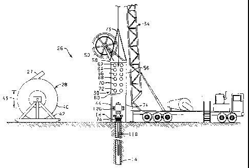
Referring now to FIG. 3, a casing patch injector unit 26
constructed in accordance with the present-invention for injecting
a tubular viscoelastic material, such as a coiled polyethylene pipe
27, into the casing 14 to form the casing patch 22 . (FIG.. 2) is
schematically illustrated. The casing patch injector unit 26
includes a reel 28 for handling and storing the polyethylene pipe
27 and a roller reduction unit 30 for directing the casing patch 22
into the casing 14, for reducing the diameter of the casing patch
22 to the desired diameter, and for partially injecting the reduced
casing patch 22 into the casing 14. A conventional workover rig 34
is also utilized in the process of positioning the.casing patch 22
in the casing 14. _
The reel 28 comprises a spool 40 rotatably mounted to a frame
42. The frame 42 is set on a suitable support surface such as the
CA 02287625 1999-10-22
ground (FIG. 3), a trailer, or offshore platform deck. The spool
40 has a core diameter 43 suitable for storing a polyethylene pipe
of sufficient outer diameter to form a compression fit against the
casing. For example, a casing having an outer diameter of 5.5
inches will have an inner diameter of about 4.95 inches. As such,
a polyethylene pipe having an outer diameter greater than 4.95
inches is required for the present invention, such as 5.25 inches,
for example.
The roller reduction unit 30 is supported above the wellhead
10 by a support structure 44. The workover rig_ 34 is also
connected to the roller reduction unit 30.so as to cooperate with
the support structure 44 to support the roller reduction unit 30
above the wellhead 10. The connection of the workover rig 34 to
the roller reduction unit 30 facilitates the rigging up and the
rigging down of the roller reduction unit 30 by enabling the roller
reduction unit 30 to be moved from a. trailer (not . shown) to its
position over the wellhead 10 and back- to the trailer once the
injection process is completed.
The roller reduction unit 30 includes a guide wheel 50 and a
support frame 56 having a first end 58 and a second end 60. The
support frame 56 supports several banks of rollers 62, 64, 66, 68,
70, and 72 which are each journaled to the support frame 56. The
rollers in each bank 62-72 are arranged to form a substantially
circular passageway 73 through which the casing patch 22 is passed.
Each subsequent bank of rollers 62-68 from the first end~58 to the
second end 60 provides the passageway 73 with a diameter smaller
11
CA 02287625 2003-07-04
than the diameter provided by the previous bank of rollers thereby
cooperating to form a substantially frusto-sonically shaped
passageway such that the outer diameter of the casing patch 22 will
be gradually reduced as the casing patch 22 is passed therethrough.
S The banks of rollers 62-68 are preferably set up to reduce the
outer diameter of the tubular viscoelastic material approximately
15%. The portion of the passageway 73 formed by the banks of
rollers 70 and 72 provide the passageway 73 with a diameter that is
the same size as the portion of the passageway 73 formed by 'the
banks of roller 68 and thus the banks of rollers 68, 70, and 72 axe
adapted to.frictionally engage the reduced casing patch 22 to
provide the thrust to snub the reduced casing patch 22 into the
casing 14 and to control the rate of entry into the casing 14.
To this end, each bank of rollers 62-72 is controlled by a
hydraulic motor (not shown?. The hydraulic motors are used to
control insertion rate of the casing patch 22- into the casing 14
with respect to injection, as well as braking of the casing patch
22.
Roller reduction units as briefly described above are well
known in the art. Thus, no further description of their
components, construction,. or operation is believed necessary~in
order for one skilled in the art to understand and implement the
method of the present invention.
The roller reduction unit 30 is supported in an elevated
position above the wellhead 10 with support structure 44, which
can include a plurality of telescoping legs 74 or other suitable
device such as a hydraulic jack stand. It should be noted that
the roller reduction unit 30 should be elevated sufficiently
W
CA 02287625 2003-07-04
above the wellhead 10 to permit access to the wellhead 10 during
the casing patch injection process. As mentioned above, the
roller reduction unit 30 is further supported by cables of the
workover rig 34 which are connected to the first end 58 of the
support frame 56 of the roller reduction unit 30.
As an example of an alternative to the roller reduction unit
30 described above, a roller reduction/wheel injector combination
can be utilized to reduce and inject the casing patch 22 into the
casing 14. Wheel injectors for injecting coiled tubing into a well
bore, such as that described in U.S. Patent No. 4,673,035, issusd
June 16, 1987, are well known in the art. When employing a wheel
injector, the roller reduction unit is disposed between the reel
28 and the wheel injector which is adapted to receive the reduced
casing patch 22 from the roller reduction unit. Like the roller
reduction unit 30, the wheel injector provides the thrust to snub
the reduced casing patch into the casing.
Reference is now made to FIG. 4 to illustrate the forming of
the casing patch 22. Initially, a length of polyethylene pipe 27
is pulled off the spool 40 (FIG. 3) and cut to a selected length.
It will be appreciated that the casing patch 22 can be formed to
any length. However, by way of example only, the casing patch 22
may be cut to have a length in a range from about 100 to about
3,000 feet, depending on the number of breaches in the casing and
13
CA 02287625 1999-10-22
their location. Upon cutting the casing patch 22 to length, an
upper connector assembly 80 is positioned in the upper end 23 of
the casing patch 22, and a lower connector assembly 82 is
positioned in the lower end 24 of the casing patch 22. The upper
connector assembly 80 includes the combination of an externally
slotted member 84, a mandrel 86 with a flanged portion 88, and a
retrieving tool 90. The lower connector assembly 82 includes the
combination of an on/off tool 92, and a mandrel 94 with a flanged
portion 96.
With the upper connector assembly 80 and the lower connector
assembly 82 positioned in the respective ends of the casing patch
22, a guide shoe 98 is fused to the upper end 23_of the casing
patch 22, and a guide shoe 100 is fused to the lower end 24 of the
casing patch 22. Each of the guide shoes 98 and 100 is a tubular
piece of viscoelastic material, preferably fabricated of the same.
material from which the casing patch 22 is fabricated, having one
end with an outer diameter equal to the outer diameter of the
casing patch 22 prior to reduction of the casing patch 22. Each
guide shoe 98 and 100 is further provided with a tapered sidewall
such that guide shoe 98 provides an internal support shoulder 102
when the guide shoe 98 is -connected to the upper end 23 of the
casing patch 22 and such that guide shoe 100 provides an internal
support shoulder 104 when the guide shoe 100 is connected to the
lower end 24 of the casing patch 22. The flanged portion 88 is
dimensioned so that it will rest on the support shoulder 102 of the
guide shoe 98 and not pass through the guide shoe 98. Likewise,
14
CA 02287625 1999-10-22
the flanged portion 96 is dimensioned so that it will rest on the
support shoulder 104 of the guide shoe 100 and not pass through the
guide shoe 100.
A cable connector assembly 106 is positioned in the distal end
of the polyethylene pipe 27 that remains on the spool 40 and a
guide shoe 108, similar to the guide shoes 98 and 100 described
above, is in turn fused to the distal end. The cable connector
assembly 106 includes the combination of a mandrel 109 having a
flanged portion 110, and a cable assembly 112. The cable assembly
112 has a short length of approximately 12 inches and is adapted to
have one end threadingly connected to the mandrel 109 of the cable
connector assembly 106 and the other end threadingly connected to
the slotted member 84 of the upper connector assembly 80 so as to
mechanically connect the casing patch 22 to .the polyethylene pipe
27 of the spool 40, which functions as a carrier for the casing
patch 22 during the reduction operation. With the casing patch 22~
connected to the polyethylene pipe 27 via the cable assembly 112,
the polyethylene pipe 27 and the casing patch 22 are wound back
onto the reel 28.
Prior to the casing patch 22 being positioned iri the casing
14, the casing 14 is cleaned with a brush or scrapper to remove
debris such as cement that may cause damage to the casing patch 22
or impede the insertion of the casing patch 22 into the casing 14.
The well ~is then killed by injecting KC1 or inserting a bridge plug
or landing anchor 116 downhole (FIGS. 8A-8D). As shown in FIG. 3,
a weight assembly 118 is then disposed and suspended in the upper
CA 02287625 1999-10-22
portion of the well bore 16. As best shown in FIG. 5, the weight
assembly 118 includes the combination of an externally slotted
member 120 which is adapted to be threadingly connected to the
mandrel 96 of the lower connector assembly 82, a string mill 122,
and a series of weights which may be in the form of a plurality of
drill collars 124 having sufficient weight for maintaining enough
tension on the casing patch 22 to keep the casing patch 22 in a
reduced state.
The weight assembly 118 can be suspended at the slotted member
120 from any convenient location, such as the wellhead 10 or from
the top of a blow out preventer 126 (FIGS. 3, 6, and 7), if
utilized, with a suitable device, such as a U-clamp (not shown) or
a pair of slips (also not shown).
As illustrated in FIG. 6, the casing patch 22 is next fed over
the guide wheel 50 and through the banks of rollers 62-72 of the
roller reduction unit 30. When the guide shoe 100 has passed
through the roller reduction injector unit 30 and is positioned
near to the slotted member 120, as shown in FIG. 6, the mandrel 94
of the lower connector assembly 82 is threadingly connected to the
slotted member 120, thereby connecting the lower connector assembly
82 to the weight assembly 118.
The lower connector assembly 82 is next caused to engage
against the internal support shoulder 102 of the guide shoe 98 and
place the reduced casing patch 22 in tension by reversing the
roller reduction injector unit 30 so as to lift up on the weight
assembly 118 so that the U-clamp or slips can be removed.
16
CA 02287625 1999-10-22
It is critical that the casing patch 22 remain in a reduced
state as the casing patch 22 is being injected into the casing 14
and until the casing patch 22 is set at the desired depth. The
lower connector assembly 82 and the weight assembly 118 cooperate
to maintain the casing patch 22 in tension as the casing patch 22
is being lowered into the casing 14 in order to sustain the casing
patch 22 in such reduced state. While the amount of weight needed
to maintain the casing patch 22 in sufficient tension will vary
depending on the size and composition of the pipe used to form the
casing patch 22, the weight assembly 118 will typically require
about 5,000 pounds of weight to maintain the casing patch 22 in
sufficient tension.
With the weight assembly 118 suspended from the lower end 24
of the casing patch 22, the roller reduction injector unit 30 is
operated to lower the casing patch 22 into the casing 14 until the
upper end 23 of the casing patch 22 is positioned near the top of
the wellhead 10 or the blow out preventer 126, as illustrated in-
FIG. 7. The casing patch 22 is then suspended from the blow out
preventer 126 or the wellhead 10 using the externally slotted
member 84 of the upper connector assembly 80 and a U-clamp or
slips. With the reduced casing patch 22 suspended in the wellbore-
16, the cable assembly 112 is disconnected from the slotted member
84 and the roller reduction injector unit 30 and the polyethylene
pipe 27 is removed from its position above the wellhead 10.
The floor (not shown) of the workover rig 34 is next lowered
over the wellhead 10 and a work string 130 (FIG. 8A and 8B), which
17
CA 02287625 1999-10-22
is made up to include a string mill 132 and a mandrel 134 at the
lower end thereof, is threadingly connected to the slotted member
84 via the mandrel 134. The U-clamp or slips are then removed and
the reduced diameter casing patch 22 is lowered down the casing 14
utilizing the work string 130 of the workover rig 34.
The landing anchor 116 is set in the casing 14 at a depth
which is below the desired setting depth of the casing patch 22 to
account for the length of the string mill 122 and the drill collars
124 extending below the casing patch 22. Thus, as illustrated in
FIG. 8B, the casing patch 22 is lowered into the casing 14 until
the bottommost drill collar 124 sets down on the landing anchor 116
and the guide shoe 100 engages and rests on the string mill 122.
The work string 130 and the upper connector assembly 80 are further
lowered until the string mill 132 of the work string 130 engages
and rests on the guide shoe 98.
With the weight of the weight assembly 118 supported on the
landing anchor 116, the tension is removed from the casing patch
22. Consequently, the casing patch 22 is allowed to expand into
position against the casing 14, as shown in FIG. SB. To assist the
expansion process, the weight of the work string 130 is maintained
on the casing patch 22 for a period of time thereby causing the
weight of the work string 130 to push the casing patch 22 out
against the casing 14.
After the casing patch 22 has expanded into position against
the casing 14, the work string 130 is rotated at the surface to
cause the string mill 132 to mill out the guide shoe 98 to permit
18
CA 02287625 1999-10-22
the work string 130 to be lowered through the casing patch 22 until
the retrieving tool 90 of the upper connecting assembly 80 connects
to the on/off tool 92 of the lower connector assembly 82 (FIG. 8C).
At this juncture with the work string 130 connected to the lower
connector assembly 82, and thus the weight assembly 118, the work
string 130 is rotated and pulled up to mill out the guide shoe 100
with the mill string 122 (FIG. 8D). With the guide shoes 98 and
100 milled out, the work string 130 along with the upper connector
assembly 80, the lower connector assembly 82, and the weight
assembly 118 are pulled up through the casing patch 22 and removed
from the well bore 16 leaving the casing patch 22 in position
against the casing 14 and effectively sealing any breaches therein.
In addition to enabling a patch having a predetermined length
to be positioned along selective portions of a casing, the method
of the present invention provides the further advantage of enabling
a series of casing patches to be set in a casing whereby the entire
length of a casing, which may be too great in length to be lined
with a single casing patch, may be lined nevertheless.
From the above description it is clear that the present
invention is well adapted to carry out the objects and to attain
the advantages mentioned herein as'well as those inherent in the
invention. While presently preferred embodiments of the invention
have been described for purposes of this disclosure, it will be
understood that numerous changes may be made which will readily
suggest themselves to those skilled in the art and which are
19
CA 02287625 1999-10-22
accomplished within the spirit of the invention disclosed and as
defined in the appended claims.