Note: Descriptions are shown in the official language in which they were submitted.
CA 02287739 1999-10-29
1
REMOVABLE HANDLE FOR CASKET
10
FIELD OF THE INVENTION
The present invention relates to a removable handle mechanism, and more
particularly, to a removable handle for caskets.
BACKGROUND
The manufacturer of casket furniture faces peculiar problems. His products are
used only once and then burnt or buried, so that logic dictates they should be
of
the cheapest and most ephemeral kind. But the mores of (at least) Western
contemporary society have, at least, since the days of Pharaoh Tutankhamun
required funerary furnishings to be of a quality proportional to the status of
the
deceased party.
It is common practice, in the casket industry, to use handles that are not
removable. The reason is that the weight of the casket requires strong handles
to
be used. These handles are either integral with the casket or they are bolted
from
the inside of the casket.
Another criteria discerning in the choice of handles in the casket industry is
their
aesthetic look. The handle design must be in good taste. Thus, it is readily
apparent that cheap-looking removable handles would be unacceptable for most
clients.
SUMMARY
An object of the present invention is to achieve almost contradicting demands
for
casket handles. Namely, to secure the handles from the inside of the casket
for
CA 02287739 1999-10-29
2
more solidity and, to provide removable handles such as to facilitate the
casket's
incineration.
The present invention provides a removable handle mechanism. It comprises at
least one anchorage having a front side and a back side. The back side is
fixedly
attached to a surface. Each anchorage has two opposite ends. One of the
opposite ends is provided with receiving grooves. The handle further comprises
at
least one sliding support adapted to slide into the receiving grooves of each
anchorage. The handle also comprises means for securing each sliding support
when engaged into the receiving grooves of each anchorage and a handle
pivotally attached to the sliding support
An advantage of the invention is that it allows repeated use of the handles
once a
casket is buried or incinerated.
Another advantage of the invention is that the handle mechanism is strong
enough
to withstand the weight of the casket.
Another advantage of the invention is that the handle is easily removable and
has
a feature that prevents the handle from falling down while removing it from
the
casket.
BRIEF DESCRIPTION OF THE DRAWINGS
Figure 1 is a side elevation view of the handle mechanism.
Figure 2 is a side elevation view of the handle mechanism wherein the handle
is
pivoted upwards.
Figure 3 is a side elevation view of the handle mechanism wherein a holding
screw is removed.
CA 02287739 1999-10-29
3
Figure 4 is a side elevation view of the handle mechanism wherein the handle
is
removed.
Figure 5 is a perspective exploded view of the anchorage and sliding support.
Figure 6 is a perspective view of the sliding support engaged in the
anchorage.
Figure 7 is front view of a casket with the handle mechanism.
Figure 8 is a front view of a casket with the handles being removed.
DETAILED DESCRIPTION
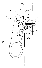
Referring now to Figures 1, 5, and 6 a handle mechanism 10 can be seen to
comprise an anchorage 12, a sliding support 24, and a handle 28. The handle 28
is pivotally attached to the sliding support 24.
The anchorage 12 has a back side 16 which is fixedly attached to a surface 18
by
means of a bolt 30 and a nut 32 also known as a "carriage bolt". The anchorage
12 has a first perforation 34, which allows the passing of the screw 30 there
through. The surface 18 can be the side of a casket. In this embodiment, the
head
of the screw 36 is on the outside of the casket and the bolt 30 is fixed from
the
inside. The bolt 30 and nut 32 combination allows the anchorage 12 to be
strongly
attached on the outside of the casket. In this embodiment, the anchorage 12 is
intended to be permanently attached on the casket. The anchorage 12 has two
opposite ends 20. One of the opposite ends is provided with grooves 22.
The anchorage 12 has a second perforation 38, which will be further described
in
connection with the other figures.
In the present embodiment of the invention the grooves 22 of the anchorage 12
face downwards when the anchorage 12 is fixed on the casket, but to those
skilled
CA 02287739 1999-10-29
4
in the art, it should be apparent that one could position the grooves in any
suitable
location as long as they allow to hold a sliding support 24 or bracket in the
anchorage by preventing an orthogonal displacement of the support 24.
Alternatively, the anchorage 12 could be integral with the surface of the
casket.
This could be the case for a steel casket for example.
The front part 14 of the anchorage 12 is partially covered by the sliding
support 24
or bracket. The support 24 has a rectangular shape, which allows the support
24
to slide into the grooves 22. The support 24 slides into the grooves 22 by
means of
lateral railings 23, engaging the support into the grooves 22 of the
anchorage12.
The support 24 has a hinge 40 on the side facing away from the anchorage 12
when the support 24 is in place. The hinge 40 has an axis of rotation
orthogonal to
the sliding direction of the support 24.
The support 24 has a perforation 42, which, when the support is slid in place
in the
grooves 22, is aligned with the second perforation 38 of the anchorage 12. A
screw 44 is inserted from the outside of the casket through the perforation 42
of
the support and the second perforation 38 of the anchorage into the surface of
the
casket for securing the support in place.
An abutment on the anchorage, extending at the extremity of the grooves
prevents
the support from sliding further inside the grooves.
The handle 28 is provided to be pivotally attached to the hinge 40 of the
sliding
support 24.
In the embodiment of the present invention, one end of the handle extends
beyond
the axis of the pivot such that this end 46 abuts on the head of the bolt 36
when
the handle 28 is pivoted.
CA 02287739 1999-10-29
Referring now to Figures 2, 3, and 4, it can be seen how the handle 28 and
sliding
support 24 can be removed from the anchorage12.
Referring now to Figure 2, the first step in removing the handle 28 is to
pivot the
5 handle 24 upwards. The screw 44 now becomes accessible for removal.
Referring now to Figure 3, the second step in removing the handle 28 is to
remove
the screw 44. As explained above, the head of the bolt 36 blocks the end 46 of
the
handle which prevents the support from sliding and handle 28 from falling
during
the removal thereof.
Referring now to Figure 4, the third and last step in removing the handle 28
is to
bring down the handle 28 first and then slide down the sliding support 24.
Referring back to Figure 2, when the handle 28 is in place on the support 24
and
the support 24 is in place in the anchorage 12, the handle can be pivoted
upwards
allowing for the transportation of the casket. The handle is pivoted downwards
when the casket is at rest, thus allowing for a reduction of the space
occupied by
the casket.
Referring now to Figure 7, the handle mechanisms 10 can be seen to be
installed
on a regular casket 48. The handles 28 are held together by a holding bar 50
used
for lifting the casket 48.
Referring now to Figure 8, the handles 28 are shown to be removed. Such is
done
by following the removal steps shown in Figures 2, 3, and 4 described above.
The handle mechanism 10 can be used on various type of surfaces, like wood or
metal. Different type of screws or bolts can be used. In the present
embodiment,
the screws are wood screws # 8. The carriage bolt is 1 '~4 " long x 10 metric
and
made of steel. Other type of screws can obviously be used, depending on the
size
of the handle mechanism.
CA 02287739 1999-10-29
6
The material used for the anchorage, sliding support, and handle is injection
molded zinc. Of course, other suitable materials can be used.
Although a preferred embodiment of the method and apparatus of the present
invention has been illustrated in the accompanying Drawings and described in
the
foregoing Detailed Description, it will be understood that the invention is
not limited
to the embodiment disclosed, but is capable of numerous rearrangements,
modifications and substitutions without departing from the spirit of the
invention as
set forth and defined by the following claim.