Language selection

Search

Patent 2288081 Summary

Third-party information liability

Some of the information on this Web page has been provided by external sources. The Government of Canada is not responsible for the accuracy, reliability or currency of the information supplied by external sources. Users wishing to rely upon this information should consult directly with the source of the information. Content provided by external sources is not subject to official languages, privacy and accessibility requirements.

Claims and Abstract availability

Any discrepancies in the text and image of the Claims and Abstract are due to differing posting times. Text of the Claims and Abstract are posted:

  • At the time the application is open to public inspection;
  • At the time of issue of the patent (grant).
(12) Patent Application: (11) CA 2288081
(54) English Title: ROTARY REGENERATIVE HEAT EXCHANGER WITH MULTIPLE LAYER BASKETS
(54) French Title: ECHANGEUR ROTATIF DE CHALEUR REGENERATIVE COMPORTANT DES COUCHES MULTIPLES DE PANIERS
Status: Deemed Abandoned and Beyond the Period of Reinstatement - Pending Response to Notice of Disregarded Communication
Bibliographic Data
(51) International Patent Classification (IPC):
  • F28D 19/04 (2006.01)
(72) Inventors :
  • RITTER, KENT E. (United States of America)
(73) Owners :
  • ALSTOM POWER INC.
(71) Applicants :
  • ALSTOM POWER INC. (United States of America)
(74) Agent: SMART & BIGGAR LP
(74) Associate agent:
(45) Issued:
(86) PCT Filing Date: 1998-03-13
(87) Open to Public Inspection: 1998-11-05
Examination requested: 1999-10-27
Availability of licence: N/A
Dedicated to the Public: N/A
(25) Language of filing: English

Patent Cooperation Treaty (PCT): Yes
(86) PCT Filing Number: PCT/US1998/004901
(87) International Publication Number: WO 1998049511
(85) National Entry: 1999-10-27

(30) Application Priority Data:
Application No. Country/Territory Date
08/848,589 (United States of America) 1997-04-28

Abstracts

English Abstract


The modular heat exchange baskets (22) for a rotary regenerative air preheater
which normally have a single stacked array of heat exchange plates, are
constructed with heat exchange plate support bars (58, 60) intermediate the
top and bottom surface. The basket (22) then has two separate stacked arrays
of heat exchange plates (62, 64) which permits the plate material or
arrangement in the top of each basket (22) to be different from the plate
material or arrangement in the bottom. For side loaded air preheaters with
basket support gratings, the arrangement of heat exchange plates (62, 64) can
be changed without the need to move the gratings.


French Abstract

Des paniers modulaires (22) d'échange de chaleur pour un dispositif rotatif de réchauffement préalable d'air régénératif possédant normalement un seul ensemble empilé de plaques d'échange de chaleur, sont conçus de manière à présenter des barres de support (58, 60) de plaques d'échange de chaleur placées en position intermédiaire entre la surface supérieure et la surface inférieure. Ce panier (22) comporte, de ce fait, deux ensembles empilés séparés de plaques (62, 65) d'échange de chaleur permettant au matériau ou à la disposition des plaques au sommet de chaque panier (22) d'être différents du matériau ou de la disposition des plaques du fond. En ce qui concerne les dispositifs de réchauffement préalable d'air à chargement latéral comportant des grilles de support de paniers, on peut modifier la disposition des plaques (62, 64) d'échange de chaleur sans qu'il soit nécessaire de déplacer les grilles.

Claims

Note: Claims are shown in the official language in which they were submitted.

6
THE EMBODIMENTS OF THE INVENTION IN WHICH AN EXCLUSIVE
PROPERTY OR PRIVILEGE IS CLAIMED ARE DEFINED AS FOLLOWS:
1. A heat transfer element basket assembly (22) for a rotary regenerative
heat exchanger comprising: a basket framework including first and second end
plates
(46,52) disposed at inner and outer ends of said basket framework and means
(54)
attaching said first and second end plates (46,52) in spaced relationship,
said basket
framework having top and bottom surfaces, and a first set of heat exchange
plate
support bars (58) extending between said first and second end plates (46,52)
adjacent
said bottom surface characterized in that
a. a second set of heat exchange plate support bars (60) extends
between said first and second end plates (46,52) at a position intermediate
said top
and bottom surfaces;
b. a first set of heat exchange plates (64) is juxtaposed in a
stacked array between said first and second end plates (46,52) and is
supported on
said first set of heat exchange plate support bars (58);
c. a second set of heat exchange plates (62) is juxtaposed in a
stacked array between said first and second end plates (46,52) and is
supported on
said second set of heat exchange plate support bars (60); and
d. a third set of heat exchange support bars (56) extend between
said first and second end plates (46,52) adjacent said top surface.
2. The heat transfer element basket assembly as recited in Claim 1 further
characterized in that said first set of heat exchange plates (64) are
different from said
second set of heat exchange plates (62).

Description

Note: Descriptions are shown in the official language in which they were submitted.


CA 02288081 1999-10-27
WO 98/49511 PCT/US98/04901
Rotary Regenerative Heat Exchanger
With Multiple Layer Baskets
Background of the Invention
. The present invention relates generally to rotary regenerative heat
exchangers and, more particularly, to improved modular heat exchange
baskets which permit flexibility in arranging various types or
configurations of heat absorbent material.
A rotary heat exchanger is employed to transfer heat from one
hot gas stream, such as a flue gas stream, to another cold gas stream,
such as combustion air. The rotor contains a mass of heat absorbent
material which is first positioned in a passageway for the hot gas stream
where heat is absorbed by the heat absorbent material. As the rotor
turns, the heated absorbent material enters the passageway for the cold
gas stream where the heat is transferred from the absorbent material to
the cold gas stream.
In a typical rotary heat exchanger, such as a rotary regenerative
air preheater, the cylindrical rotor is disposed on a vertical central rotor
post and divided into a plurality of sector-shaped compartments by a
plurality of radial partitions or diaphragms extending from the rotor post
to the outer peripheral shell of the rotor. These sector-shaped
compartments are loaded with modular heat exchange baskets which
contain the mass of heat absorbent material commonly comprised of
stacked plate-like elements.
The rotor is surrounded by a housing and the ends of the rotor are
partially covered by sectcr plates which divide the housing into gas and
~ air sides. In order to improve the efficiency of operation, it is
conventional to provide seals, which are referred to as radial seals, on
the ends of the rotor such that the seals will come into proximity with
the sector plates and minimize-the flow or leakage between the air and

CA 02288081 1999-10-27
2
gas sides at the ends of the rotor. These seals are normally attached to the
edges of
the diaphragms.
The modular heat exchanger baskets may be of the open frame type or they
may have solid side walls. Also, the baskets may be loaded axially into the
sector-
shaped compartments of the rotor from the top end or they may be loaded
radially
through the periphery of the rotor. In the former case, the modules sit on top
of each
other. In the latter case, the baskets are supported on gratings fixed between
the
diaphragms at each end of the rotor and between layers of baskets.
In rotary regenerative heat exchangers, it is often desirable to employ
different
forms of heat absorbent material or plate at various levels. For example, the
material
at the hot end of the rotor where the hot gases enter and the heated air exits
may need
to be quite different from the material at the cold end, or for that matter,
at the center.
Therefore, it is advantageous to be able to vary these heat exchange materials
in the
baskets with varying conditions. With conventional types of rotors and
baskets, this
can only be done by completely changing the mass of heat exchange material for
a
particular level of baskets or by modifying the rotor structure (grate
location) and the
basket design (axial height).
One example of such a conventional type of rotor and baskets is that which
forms the subject matter of Document US-A-5 454 418 wherein there is disclosed
a
heat transfer element basket assembly for a rotary regenerative heat exchanger
comprising a) a basket framework including first and second end plates
disposed at
the inner and outer ends of said basket framework and means attaching said
first and
second end plates in spaced relationship and wherein said basket framework has
top
and bottom surfaces, and b) a first set of heat exchange plate support bars
extending
between said first and second end plates adjacent said bottom surface.

CA 02288081 1999-10-27
2a
Summary of the Invention
The present invention relates to a rotary regenerative heat exchanger and to a
novel modular heat exchange basket for use in the heat exchanger. At least
some of
the heat exchange baskets are constructed such that multiple levels of
different heat
absorbent material can be placed in each basket. Specifically, support means
are
located in such baskets at a selected level between the top and bottom of the
basket
such that heat exchange material of one type can be located above that support
means
and heat exchange material of another type

CA 02288081 1999-10-27
WO 98/49511 PCT/US98/04901
3
can be located below that support means. The support means in the
module can be changed to vary the proportions without needing to
change the support gratings of the rotor structure.
Brief Description of the Drawings
Fig. 1 is a general perspective view of a rotary regenerative air
preheater.
Fig. 2 is a top cross section view of a portion of the rotor of the
preheater of Fig. 1 illustrating the support gratings in position between
diaphragms.
Fig. 3 is a perspective view of a typical prior art modular heat
exchange basket.
Fig. 4 is a perspective view of a basket similar to Fig. 3 and
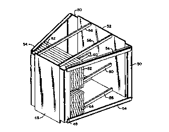
illustrating the present invention.
Description of the Preferred Embodiment
Fig. 1 of the drawings is a partially cut-away perspective view of
a typical air heater showing a housing 12 in which the rotor 14 is
mounted on drive shaft or post 16 for rotation as indicated by the arrow
18. The rotor is composed of a plurality of sectors 20 with each sector
containing a number of basket modules 22 and with each sector being
defined by the diaphragms 34. The basket modules contain the heat
exchange surface. The housing is divided by means of the flow
impervious sector plate 24 into a flue gas side and an air side. A
corresponding sector plate is also located on the hottom of the unit.
. The hot flue gases enter the air heater through the gas inlet duct 26,
flow through the rotor where heat is transferred to the rotor and then
exit through gas outlet duct 28. The countercurrent flowing air enters
through air inlet duct 30, flows through the rotor where it picks up heat
and then exits through air outlet duct 32.

CA 02288081 1999-10-27
WO 98/49511 PCT/US98/04901
4
Although the present invention can be applied to air preheaters
which are axially loaded from the top, the invention is particularly
applicable to air preheaters which contain basket support gratings and
which are radially loaded through the periphery of the rotor. Therefore,
the invention will be described with reference to radial loading.
Referring now to Fig. 2 which shows a plan view in cross section
of a portion of a rotor, the diaphragms 34 are shown in cross section
extending radially between the central portion 36 of the rotor and the
rotor shell 38. This Fig. 2 is a view before the basket modules have
been installed. Supported between and attached to the diaphragms 34
are the support gratings 40. These support gratings are formed from
the members 42 and are normally truss-like structures. Any desired
truss configuration can be used as long as it is structurally designed to
support the baskets. The gratings are suitably attached to the
diaphragms 34 such as by welding. As is conventional, there are a
plurality of levels of gratings in each sector.
Fig. 3 illustrates a single, prior art heat transfer element basket
22 showing a portion of the heat transfer plates 44. Of course, the
basket would be filled with these heat transfer plates but the remainder
have been omitted for clarity. The frame of the basket 22 comprises a
nose piece or inner end 46 which is bent outwardly at the sides to form
the corners 48. The outer end of the basket is defined by the outboard
corner angles 50 which are attached by welding to the outer end piece
52. The inner and outer ends are connected by the welded side angles
54 and the upper and lower tie bars 56 and 58 respectively. All of
these members together form the basic framework of the basket.
Although the sides of the basket have been illustrated as being open,
they could also be closed by metal side plates. As seen in this Figure
3, the heat transfer plates 44 extend from the top to the bottom of the
basket and are supported on the lower tie bars 58.

CA 02288081 1999-10-27
WO 98/49511 PCT/US98/04901
Figure 43 illustrates the present invention as it would be applied
to the prior art basket of Figure 3. In Figure 4, additional tie bars 60 are
provided which are located between the upper and lower tie bars 56 and
58. Although these tie bars 60 are illustrated as being approximately
mid way between the top and bottom, they can be located at any
desired level.
As illustrated in Figure 4, the heat transfer plates in the basket 22
of the present invention are now divided into a group of upper plates 62
and a group of lower plates 64. The upper and lower groups of plates
can now be formed of different material or formed in different
configurations as desired for a particular application. For example, the
plates 62 in the top of the basket may be of one material, spacing or
configuration, while the plates 64 in the bottom of the basket may be
of a different material, spacing or configuration. As shown in Figure 4,
the plates 64 are spaced wider apart than the plates 62.
The present invention permits the heat exchange plates within
each basket section to be changed as desired to change the mix of
different types of plates in the overall air preheater. This can eliminate
the necessity to make changes in the basic rotor construction, such as
changing the location of gratings, in order to adjust that mix. The
support bars in each basket can now be located or moved to give the
optimum performance without altering the rotor structure.

Representative Drawing
A single figure which represents the drawing illustrating the invention.
Administrative Status

2024-08-01:As part of the Next Generation Patents (NGP) transition, the Canadian Patents Database (CPD) now contains a more detailed Event History, which replicates the Event Log of our new back-office solution.

Please note that "Inactive:" events refers to events no longer in use in our new back-office solution.

For a clearer understanding of the status of the application/patent presented on this page, the site Disclaimer , as well as the definitions for Patent , Event History , Maintenance Fee  and Payment History  should be consulted.

Event History

Description Date
Application Not Reinstated by Deadline 2003-03-13
Time Limit for Reversal Expired 2003-03-13
Deemed Abandoned - Failure to Respond to Maintenance Fee Notice 2002-03-13
Letter Sent 2001-08-09
Letter Sent 2001-08-08
Inactive: Cover page published 1999-12-21
Inactive: First IPC assigned 1999-12-13
Inactive: Acknowledgment of national entry - RFE 1999-11-30
Letter Sent 1999-11-30
Application Received - PCT 1999-11-26
Request for Examination Requirements Determined Compliant 1999-10-27
Amendment Received - Voluntary Amendment 1999-10-27
All Requirements for Examination Determined Compliant 1999-10-27
Application Published (Open to Public Inspection) 1998-11-05

Abandonment History

Abandonment Date Reason Reinstatement Date
2002-03-13

Maintenance Fee

The last payment was received on 2001-01-03

Note : If the full payment has not been received on or before the date indicated, a further fee may be required which may be one of the following

  • the reinstatement fee;
  • the late payment fee; or
  • additional fee to reverse deemed expiry.

Please refer to the CIPO Patent Fees web page to see all current fee amounts.

Fee History

Fee Type Anniversary Year Due Date Paid Date
Basic national fee - standard 1999-10-27
Registration of a document 1999-10-27
Request for examination - standard 1999-10-27
MF (application, 2nd anniv.) - standard 02 2000-03-13 1999-12-13
MF (application, 3rd anniv.) - standard 03 2001-03-13 2001-01-03
Registration of a document 2001-06-21
Owners on Record

Note: Records showing the ownership history in alphabetical order.

Current Owners on Record
ALSTOM POWER INC.
Past Owners on Record
KENT E. RITTER
Past Owners that do not appear in the "Owners on Record" listing will appear in other documentation within the application.
Documents

To view selected files, please enter reCAPTCHA code :


To view images, click a link in the Document Description column. To download the documents, select one or more checkboxes in the first column and then click the "Download Selected in PDF format (Zip Archive)" or the "Download Selected as Single PDF" button.

List of published and non-published patent-specific documents on the CPD .

If you have any difficulty accessing content, you can call the Client Service Centre at 1-866-997-1936 or send them an e-mail at CIPO Client Service Centre.


Document
Description 
Date
(yyyy-mm-dd) 
Number of pages   Size of Image (KB) 
Representative drawing 1999-12-21 1 13
Description 1999-10-27 5 205
Abstract 1999-10-27 1 56
Claims 1999-10-27 1 30
Drawings 1999-10-27 4 103
Claims 1999-10-28 1 39
Description 1999-10-28 6 221
Cover Page 1999-12-21 1 57
Reminder of maintenance fee due 1999-11-30 1 111
Notice of National Entry 1999-11-30 1 202
Courtesy - Certificate of registration (related document(s)) 1999-11-30 1 115
Courtesy - Abandonment Letter (Maintenance Fee) 2002-04-10 1 182
PCT 1999-10-27 10 333