Note: Descriptions are shown in the official language in which they were submitted.
CA 02288314 1999-11-02
P-12481.JSS
ag\f:\work\030\P12981\SPGC\P12901.JSS
fIITLTICHANNEL IMPLANTABLE INNER )3AR STIMULATOR
Backaround of the Invent'inn
The present invention relates.to a system and
method for electrical stimulation of the inner ear. More
particularly, the present invention relates to an
implantable device for electrical stimulation of the 8tf
JS nerve. Even more particularly, the present invention
relates to an implantable device for electrical
stimulation of the 8th nerve to produce the sensation of
hearing.
It is well known that brain and nerve impulses
are electrical in nature. It is also known that
electrical stimuli applied to receptor centers such as
the nerves cause a reaction dependent on the electrical
characteristics of the stimuli. Many devices utilize
these characteristics to compensate for defective
performance of sensory organs of the body.
In normal hearing, the hair cells are a
critical linJc in the hearing chain. They serve two
functions in association with the brain: (1) they
establish a background nerve activity that is perceived
as silence ("active silence" as described below); and (2)
CA 02288314 1999-11-02
P-12481.JSS
~9\f:\work\030\P12481\SPEC\P12981.JSS
when sound enters the ear, they generate a potential that
varies and modulates this bac)cground nerve activity in
response to the sound. The resulting nerve activity is a
constant plus the derivative of the atmospheric pressure.
This derivative or rate of change of pressure carries the
sound information. Important to the present invention is
the recognition that the rate or frequency or density of
the resultant nerve activity may be viewed as a carrier
modulated by sound.
In the profoundly deaf patient, the principal
cause of deafness is the loss of function of the hair
cells. In 300 of the deaf, the loss of nerve fibers from
the spiral ganglion to the non-functioning hair cells is
a contributory cause of deafness . Tii:i.s may .bP ,.all ;ar d~.~.P
I5 l:U :Llla:.'l:i~,l'l.l:y C~'f tl'lf: xi~3:"~iE: fi~JC'rS .frUtTl I:IlF.'.
::a?r C:E.:11S Lf')
tie sJ.»-r~~l g~~l~glion. Therefore, to restore hearing to a
person with a partial or total (profound) loss of
hearing, a replacement of these functions is required
past the point of los:~ of funr:t orl, t:-lat is pit a hi~.~rlfr
2U 1 i nl: Lo t~~:e ~~LliI1 .
In the case of the ear and associated hearing
functions, many devices have been designed to
electrically stimulate the auditory nerve of the human
body, which is known as the 8"' cranial nerve. However,
25 these devices operate on principles derived from an
inappropriate extrapolation of certain observations made
by Beckesy in the 1930~s. Beckesy~s observations
concerned the Basilar membrane, which extends the entire
length of the Cochlea. These observations revealed that
30 the Hasilar membrane vibrates in response to sound
-2-
CA 02288314 1999-11-02
P-12481.JSS
ag\f:\work\030\P12981\SPEC\P12981.JSS
vibrations that enter the ear. It was observed by
Beckesy, and confirmed by others, that the sound
vibrations caused the membrane to vibrate with a standing
wave wherein the maximum amplitude of the standing wave
occurred at a location on the membrane dependent on the
frequency of the entering sound vibrations. Individual
hair cell activity at these locations was also
particularly pronounced at the locations of the maximum
amplitude of the standing wave. High frequencies result
in a maximum amplitude at the entrance to the Cochlea.
As the frequency decreases, the location of this maximum
amplitude moves toward the extreme end of the Cochlea.
While this mechanical action is true and
individual hair cell activity is emphasized at these
15 maximum amplitude locations, others have inappropriately
extrapolated these observations to conclude that hearing
was effected by the response of the individual nerve
fibers along the length of the Cochlea that were
frequency dependent. Thus, the theory developed, lcnown
as the Place Theory of hearing, that the nerve fibers in
. the Cochlea conduct different frequencies to the brain
dependent on their location in the Cochlea. It is
curious that the absolute length of the cochlear duct,
which varies from 5 mm in the chicken to over 100 mm in
25 the whale, does not seem to play a very important role in
the frequency range of the Cochlea, i.e., the whale has a
slightly greater frequency range than a chicken even
though the Place Theory of hearing would suggests that,
with a Cochlea that is 20 times longer, the whale's
-3-
CA 02288314 1999-11-02
P-12481.JSS
ag\f:\work\030\P12481\SPEC\P12481.JSS
frequency range should be 20 times greater than the
chicken's.
The Place Theory of hearing requires that the
nerves in the Cochlea operate in a manner different from
the manner in which.all other nerves in the body operate.
The present invention is based on a model of hearing that _
is entirely different than the Place Theory. This'
invention, in contrast to the Place Theory, is based upon
the application of signal processing principles to the
function of the nerve fibers of the 8't' nerve terminating
in the vestibule and Cochlea, much like the.operation of
modern communication receivers that use Digital Signal
Processing to reduce noise and process information.
The nerves terminating in the Vestibule and!o:
Cochlea t:l?;:~Y: tr~~msLc:x~ sr~ur_.d sensatioci are non-specific .
and may be fired in sequence or as a sustained background
~erve activity by a single pulse which, when modulated,
produces the sensation of the sound of the modulation for
a given period of time. Accordingly, given the
principles guiding the present invention, the nerve
fibers in the g"' nerve operate in a manner identical to
those throughout the body. In particular, the signal sent
by the nerves is non-specific but the number of nerves
firing and the rate of firing conveys information to the
brain that the brain translates into sound. The number
of nerve fibers firing simultaneously or at sn,~..h a h7.~.h
rw.~:r_t:it:i.ar: w;~~Le t::at :it: ::rppF.= irn
=irs s ul~~c~Tie_'U~IIS is a
function of the instantaneous sound intensity, vari~~t,~.~lla
of th~.s n.erva act i vity i s perceived as s.oum~~.
-4-
CA 02288314 1999-11-02
P-12481.JSS
ag\f:\work\030\P12481\SPEC\P124A1.JSs
The model of hearing upon which the present
invention is based recognizes that mar..~r nerve fibers of
the Cochlea have functions other than the conduction of
sound. Tt is recognized that the very regular and
orderly spatial arrangement of the sensory elements in
the Cochlea predispose it to work on the basis of spatial
principles, however, not in accordance with the Place
Theory of hearing. It has been observed that stimulation
of many of these fibers does not produce the sensation of
sound. The brain utilizes the Cochlea as a mechanism to
control the sound pressure variations as a result of the
sound vibrations and thereby serve as a means of volume
control.
In this mode, some of the outer hair cells of
the Cochlea sense the motion of the Hasilar membrane,
transmit this information to the brain which in turn
sends baclc signals to many of the hair cells in the
Cochlea to control the stiffness of the Basilar membrane
and thereby control the InE:c:i~~~:r:~.r~:;i impedance at the
entrance from the Vestibule to the Cochlea. This then
allows for an automatic volume control (in the mechanical
domain) and possibly a means of controlling the frequency
response to improve intelligibility. Ch~tngi::q t:~E~
Ili(_:GIOeiI:lCi.'ll chara~~teri:~tics of t-~c~ Basilar rnenWrane:
c:.,ai-..ge s t.h a ma~c:~an ical transfer of enera~~ to the h air.
cP:l.:l s thus etl:e::cr i.ng sensi.t ~.v.~.ty and f r. e~~.~Przcr~ i-
esprm.:~P .
The Cochlea may also contribute to the process of sound
localization.
Audio signals of speech and music are found to
have most of their energy concentrated in the lower-
-5-
CA 02288314 1999-11-02
P-12481.JSS
ag\f:\work\030\P129p1\SPEC\P124p1.JSS
frequency ranges. To achieve an improvement in the
signal-to-noise ratio, preemphasis (boosting the gain of
a signal) of the high frequencies should be observed and
a corresponding deemphasis at the detection in the brain.
Consistent with t$is.notion, Bec)csey published in 1960
that patterns of vibration of the Cochlear partition of
cadavers for various frequencies showed a preemphasis of
the high frequencies in the first 10-mm distance from the
stapes. In 1974, Rhode published a graph of the input-
output ratio, in decibels, for the Malleus and Basilar
membrane ( F.1.~~ . 21t? ) . The graph shows an increase of 6dB
per octave (or 20 dB per decade) of the frequencies
between 200 Hz and BkHz. Also figure 21B shows that a
broad range of frequencies stimulates the hair cells in
this area. These observations t~er~d t_o :~upp«rt tale
LOIICc?ht of pre:emp:zasi:~. Observations ~~lso suggest that
the outer hair cells of the Cochlea function to provide
information to the brain to control volume, the dynamic
range and have an effect on frequency response rather
than to transmit the sensation of particular frequencies
to the brain.
In addition, it is not generally known that the
nerve activity that produces sound consists of the
summation of the nerve activity in response to external
sound or stimuli modulating a constant background nerve
activity. This constant background nerve activity was
described by R. Lorente De No in 1976 as follows, ~~In the
absence of peripheral stimulation, the acoustic nuclei
are the site of continuous activity maintained by the
arrival of nerve impulses spontaneously initiated in the
-G-
CA 02288314 1999-11-02
P-12481.JSS
ag\f:\work\030\p12981\SPEC\P12901.JSS
Cochlea. The activity is necessarily accompanied by
circulation of impulses in chains of neurons.
Since spontaneous activity in the cochlea and
in the acoustic centers is perceived by humans as
silence, it must be. concluded that the spontaneous
activity serves to determine the background states of the
various subdivisions of the acoustic nuclei, to which the
deviations caused by sound are referred. In other words,
what we hear is the result of those deviations from the
ground states or baseline signal of the acoustic nuclei,
which are caused by external sources of sound." He refers
to this background state as "active silence" to which
perception of sound is referred.
While others have observed this activity, none
has recognized it as a carrier that is t~hr.: sua,o~:~t:; ors ~~ f
non-specific ne:r;Tc acti.:rity and modulated by external
stimuli. The recognition of this principle is an
important element of the present invention. This
recognition is consistent with the sample data-theorem
developed by Hartley of Bell Labs and Nyquist in 1928
when one considers the "active silence" as a carrier
frequency.
It is not necessary that the nerve activity be
a sequence~of single nerve fiber activity but that the
nerve activity is at such a high frequency that it is
beyond the range of audible sound, paring or multiples of
simultaneous nerve findings may occur. Active silence
can be compared to the molecular activity of a gas at a '
given pressure (silence) and the modulation of this
activity by pressure variations due to sound.
CA 02288314 1999-11-02
P-Za~al.JSs
eg\P:\work\030\P12481\SPEC\P12481.JSS
The mechanical characteristics of the Hasilar
membrane at the entrance to the Cochlea (see Fig. 21?a an~i.
1B) are such that the modulation is maximum for high
frequencies and reduces at a rate of 6 dB per octave to
the lower frequencies. Audio signals of speech and music
are found to have most of their energy concentrated in
the lower-frequency ranges. The emphasis of the high
frequency components of the audio signal is introduced
before the nerve activity noise is introduced, to the
point where they produce a constant deviation of the
background nerve activity as a function of .frequency.
This equalization, of the low frequency and high
frequency portions of the audio spectrum, enables the
signal to fully occupy the bandwidth of the neuron
IS communication link. The spectrum of the noise introduced
at the nerve summation output occupies the entire
bandwidth. The noise-power spectrum at the output
summation is emphasized at the higher frequencies. At the
summation output of the nerve fibers the inverse
20 function, deemphasis is introduced to the
higher-frequency components, which restores the original
signal-power distribution. This deemphasis process
reduces the high-frequency components of the noise also
and so effectively increase the signal-to-noise ratio.
25 This funcfion of accentuating the high
frequencies compensates for an inverse function at the
far end~of the nerve bundle in the brain. It is similar
to accentuating the high frequencies in a FM transmitter
and subsequently attenuating high frequencies at the
30 receiver. The result is, with the Basilar membrane
_g_
CA 02288314 1999-11-02
P-12481.JS5
ag\f:\work\030\P12981\SPEC\P12981.JSS
compensation for the brain "receiver" functions, an
improved signal-to-noise ratio. A secondary
characteristic of the Cochlea is that all frequencies do
in fact stimulate nerve fibers near the Vestibule ~~t~i t,;l
pievmpha sis . E:igh frequencis s dom~.nate the entrance and
low frequencies dominate the other end. However, the
sensing of a frequency is not related to which nerve
fibers are stimulated but rather to the change in overall
nerve fiber activity when looking at the summation of all
nerve fiber activity (see Fig. 20y
The foregoing function of the Cochlea might be
compared to a woofer, mid-range and tweeter speaker
system. When the sounds arrive at the ear, an individual
hears the summation of the activity of each of the
15 speakers. Similarly, the brain receives signals that
constitute the summation of the activity and signals sent
by the hair cells and the associated nerve activity.
Importantly, however, the nerve activity associated with
each stimulated hair cell makes a contribution to t.T,4
20 ;~ummateci nerve activit~~ entirely independent of the
contribution made by the nerve activity of other
stimulated hair cells b»t i.s rfA:maPd l.~y ot;~P,: nP3.-vP
a~=tv~%=i~y. Thus, oftentimes, when observed in isolation,
the nerve activity seemed to be frequency selective.
25 However, when looked at closer in light of the
recognition of the spontaneous or background activity of
the hair cells as a carrier frequency for sound stimuli
received, the recognition of the present invention that
the modulation of background or spontaneous nerve
30 activity is what is "heard", not the nerve activity
-9-
CA 02288314 1999-11-02
P-12481.JSS
ag\f:\work\030\p12981\SPEC\P12481.JSS
associated with individual hair cells, becomes apparent.
While it is true that different frequencies may
ixicreasr= activitir of nerve fibers in different areas of
the Cochlea, this does not effect the transmission of
sound. The summed change in nerve activity from the
Vestibule and the Cochlea is heard as sound, not which
nerve fiber is. activated at any time or when a given
frequency is heard. This concept was first suggested by
Rinne in 1865 but he had no formal theory to put forward.
In 1880 Rutherford provided a plausible explanation, the
TELEPHONE THEORY. However at that time little was known
of nerve fiber characteristics and it would be almost 50
years before Hartley~s and Nyquist~s SAMPLE DATA THEOREM.
The physiological characteristics of the 8t"
IS auditory nerve are likewise important in designing any
system based on the theory of hearing adopted above. In
particular, five characteristics play an important role
in the design of any such system: strength-duration,
streaming, latency, recovery, and fatigue. The strength-
duration characteristics of the human nerve fibers are
graphically represented by the strength-duration curve
shown in Figure lA. The strength duration curve
expresses the relation between least strength of an
applied current (stimulus) to the nerve fiber and the
least time during which the current (stimulus) must flow
to reach a threshold for excitation. Expressed another
way, the strength-duration curve is a plot of the
threshold intensity just capable of exciting an axon and
its relationship to the duration of the stimulus current.
Indeed, nerve fibers will not excite in response to
' -10-
CA 02288314 1999-11-02
P-12481.JSS
~g\f:\work\030\P12401\ShEC\Y1?.401.JSS
current densities below a minimum. The strength-duration
curve is further described in Medical Physiology and
Biophysics, Ruch and Fulton, 18th Edition, W.B.Saunders &
Co. Ruch and Fulton model this nerve behavior after a
single resistance capacitance circuit. Strength duration
combined with a gradient electric field determines the
range of pulse length for a stimulus pulse to cause
"streaming."
Streaming is the sequential firing of nerve
JD fibers within a group of nerve fibers or ganglia that
have been stimulated by a single-pulse stimulus. Upon
stimulation by a single-pulse stimulus such as a single
square wave through action of a gradient electrical field
impinging on a group of nerve fibers or ganglia, the
individual nerve fibers within the group will each
receive a stimulus decreasing in intensity as the
individual nerve fibers within the group increase in
distance from the source electrode. This phenomenon is
shown in Figure 1B. The tiring rate of the individual
2~ nerve fiber will correspond to that shown in the
strength-duration curve of Figure 1A. Thus, ~~~hen the
individual nerve fibers within a st~.rmz:J.at,-.rc.~, net-ve group
c:omr;ieri;:cfig°ixzc~, those closer to the origin of the
gradient field will fire at a greater rate while those
25 f_arthc?r a~.lay will fire at a slower rate.
Thus, the nerve group will transmit a series of
signals, i . e. , a stream of x~cz-~;ra ~z;:Glv:itl,, over time . In
particular, this "streaming" is characterized in that
~ome nerves ii: the group will fire in succession, which
CA 02288314 1999-11-02
P-12481.JSS
ag\f:\work\030\P12A81\SPEC\P12481.JSS
successive firings occurring at a slower rate than the
previous fixing.
Streaming occurs during the latter portion of a
single nerve pulse stimulus. The length of streaming of
a group of nerve fibers is limited by the delay of the
start of streaming at the beginning of the pulse (no
sooner than 0.1 milliseconds according to the strength-
duration curve of Figure lA) and the time remaining to
the end of the stimulus pulse. This behavior is show : at
the top portion of the graph of Figure lA by the line
labeled as the "Nerve Firing Rate." The latency period
is the delay between the start of the stimulus pulse and
the firing of a nerve fiber.
Reference to Figure lA sh.oc,rs t.ha.t the :t,,~.ten~-,~,.
t: i mc:~ ax~ G.~c:h nexvYC: f i bc:x~ is d:if f event cts de.f ? rzE~d by
thc:
strr~nytil-ciuratinn Cul"VE: illid tl:e r.~iadicmt fir~lci. :Ln
practice it is ciesirable to have' the star_t.ing of
;~tr.eam:i.rzg to be ri.e:l.a.yed b~.~ more ti~arx «.2 ms. ,~s fi:.rie
lat:enc:y tittle :1.5 SaU'.Y.'tE'_Tled ~7~.' vzxr.:r~:as:irzg t:ze stiruzlus
amplitude, the compensation cnn~l~orl,~I:L ncces;~ar.~ tn ~~
t'~e clifzerent~.a1 lat.ej:cy time, co~~st.aj:t during streaming
~'rqn:i.~:e.:~ n.r..rr-_ases t.hr-. .:~t,.nu~:l.tzs to an p.xcr-_sal.ve
;xmp:l.i.tudP
for a sysLenin with a long st,_..eamyng t-:iiri~:, (;as ir1 t:l~e d
chartncl system) . The minimum latency period also
determines the overlay time for adjacent channels i.e.,
the time in which the adjacent or other nerve fibers must
be stimulated to continue the transmission of the total
signal once the original nerve fiber ch~~iir~~~l enters the
recovery stage.
-12-
CA 02288314 1999-11-02
P-12481.JSS
ag\f:\work\030\P12981\SPEC\P12981.JSS
Moreover, the 8'h nerve ii:div ideal f ~.~~er s a,-~
not capable of indefinitely transmitting stimuli. After
receiving and transmitting a stimulus, the nerve must go
through a recovery period. Absent this, the nerve will
fatigue and will cease transmitting. The recovery
characteristics of the nerve limit the repetition rate of
individual channel stimulation. Lasi:l~.~ rfex.~,.E,s ~;mE: ynn~~~3.c:d
by prolnnr~ed :stimulus wit=: an average DC component. All
such stimuli must be made in an AC fashion.
When an electrical field impinges on t:l~e
tu.~d.itoxy~ sensory branch of the 8tr' nerve including the
brain stem or the spiral ganglion, the angle of arrival
produces a gradient field across the nerve group that can
causes the nerves to tire in sequence. This is
.j
15 illustrated in Figure lC,.which indicates how the
strength of an electric field decreases across a group of
nerve fibers, between a cathode and an anode. Because of
this decreasing strength electric field, the nerve fibers
fire in sequence. In addition, because of the
20 combination of the electric field and the strength-
duration characteristics of the nerve fibers, as the
distance from the cathode increase, the time between
successive nerve firings also increases. In contrast,
with the arrangement shown in Figure 1D, all of the nerve
25 fibers are subject to substantially the same electric
potential and will thus fire substantially
simultaneously.
If the stimulus amplitude is small, so as not
to produce a high enough carrier frequency to be above
30 the range of hearing the streaming frequency can be
-13-
CA 02288314 1999-11-02
P-12481.JSS
ag\f:\work\030\P12981\SPEC\P12481.JSS
heard. Its frequency is a function of the stimulus
place on the strength-duration curve in relation to the
nerve fibers stimulated and the curve's slope. This
varies with time and amplitude of the stimulus. As
mentioned above, the signal sent by the nerves is non-
specific but the number of nerves firing and the rate of
firing conveys information to the brain that the brain
translates into sound. For example, as the amplitude is
increased, the rate of sequential nerve fiber firing
increases . If the angle ol: ~. at.zma:l.txs is near
perpendicular a high rate of sequential firing will
occur ~z;; the incii~.~iciual Ii~h'trE: fiber; of a cl:anncl rcceivc;
clo''e to the same s,t imulati oIl. If the angle is small
the sequential firing is at a lower frequency as th.e
di.~::~E?'.~'~lls:r~ «f sl:irnzlatimn ciC:x'USS the: inci:~:i.dual ixF~ ,
r'J E.
fibr~rs stimulatr~d will h j a >
~~ r a great',.. r ,
m- clLge , .
Known devices which are designed to aid the
profoundly deaf by electrical stimulation of the 8t'' nerve
but on principles guided by the Place Theory, however,
function ,prirnarill~ because of this angle and stimulus
dependency, but with results that are not predictable,
repeatable or optimized. In U.S. Patent No. 3,449,768,
issued to James Doyle, the system was not designed based
on principles of the Place Theory of hearing but was
designed to produce a carrier of nerve activity based on
multiple channels stimulated in sequence at a rate
sufficiently high to result in a carrier of nerve
activity suitable for modulation with sound information.
That patent discloses a device for applying electrical
stimuli to the 8'" cranial nerve and includes an
-1LE_
CA 02288314 1999-11-02
P-12481.JSS
ag\f:\work\030\p12981\SPEC\P12981.JSS
electrode system for placement in the vicinity of the
auditory nerve, means for feeding pulses to a plurality
of transmission channels and a modulator which modulates
a time-amplitude integral of each of the pulses.
This system was limited because, for example,
of the number of channels required and the recovery time
allowed for each channel was too short to allow for
prolonged stimulus without causing nerve fatigue. No
consideration was given to the latency characteristics of
nerve fibers (the delay between the start of the stimulus
pulse and the firing of a nerve fiber). Moreover, the
earlier Doyle system failed to allow for compensation in
the stimulus strength to maintain a constant nerve firing
rate and overcome the inherent slowing due to streaming,
as described above. Lastly, the earlier Doyle patent did
not recognize or teach that the carrier frequency (the
frequency or density of the background nerve activity) is
independent of the rate at which the individual channels
are being fired and the number of the individual
channels. These limitations or failures resulted in a
system with low sound fidelity, a signal to noise ratio
that is lower than can be achieved otherwise, and a
constant hum or tone perceived by the patient.
Summary of the Tnvention
An object of this invention is to improve
systems~for stimulating the auditory. nerve of the human
body.
-15-
CA 02288314 1999-11-02
P-12481.JSS
ag\f:\work\030\P12981\SPEC\P12481.JSS
Another object of the present invention is to
improve the system disclosed in U.S. Patent No.
3,449,768, issued to James Doyle.
A further object of this invention is to
produce continuous nerve activity mimicking the
~,. spontaneous nerve activity present in normal hearing and
to modulate this nerve activity with an audio signal to
provide hearing.
A further object of this invention is to
provide a new system for stimulating groups or bundles of
nerve fibers of the 8th cranial nerve in a manner to
cause channel streaming at a constant rate.
Still another object of the present invention
is to accomplish this constant rate streaming in a manner
15 that accounts for the strength-duration characteristics
of the nerves.
Another object of this invention is to modulate
this channel streaming with audio information to produce
hearing for the profoundly deaf or those with other
20 hearing impediments.
The present invention provides a new system for
stimulating groups or bundles of nerve fibers of the gtn
cranial nerve in a manner to cause channel streaming at a
constant rate. With the preferred embodiment of the
25 invention disclosed herein in detail, unlike any prior
art device, this constant rate streaming is accomplished
in a manner that accounts for the strength-duration
characteristics of the nerves. Further, the system
modulates this channel streaming with audio information
to produce hearing for the profoundly deaf or those with
-16-
CA 02288314 1999-11-02
P-12481.JSS
ag\f:\work\030\P124B1\SPEC\P12481.JSS
other hearing impediments. The present invention
provides further a method for stimulating these groups or
bundles of nerve fibers.
In accordance with the preferred embodiment of
v 5 this invention, an electrical stimulus is applied so as
to cause nerve firing at a constant rate. The increase
in stimulus strength provided by the device of the
present invention is governed by the strength-duration
characteristics or behavior of the nerve fibers or
gang:l.i.a. By adjusting the gradient field generated by
the electrode: placed in proxirn.i.ty to t.m 8r' izc~r-ve for
the nerve characteristics represented by the strength-
duration curve, the individual nerve fibers located
within the gradient field need not fire simultaneously
'~%'l~:r; si::imulal:ed, as taught in the prior art, but will
fire in a sequence of nerve activity as time progresses.
Preferably, the stimulus does not occur at the
extremes of the strength-duration curve. This is because
the high voltage needed to obtain a very short latency
20 period may produce undesirable electromechanical
reactions. Also, a long latency period results in an
excessive channel overlap and reduces the available time
per channel for streaming. For instance, preferably, the
latency period is kept between 0.1 and.4.0 milliseconds;
25 and even more preferably, the latency period may be
maintained between 2 and 3 milliseconds. It should be
noted that the preferred latency period may vary
depending on the specific subject.or patient, and, with
some individuals it may be appropriate or preferred to
operate outside of the
-17-
CA 02288314 1999-11-02
P-12481.JSS
ag\f:\work\030\P12401\SPEC\P12401.JSS
above-described ranges.
While this streaming of nerve activity takes
place, the device of the present invention modulates the
stimulus pulse to vary the nerve activity rate and cause
the transmission of~signals to the brain by the gtr' nerve
or the ganglia that are perceived as hearing. Tfi a;~.fio
Tnc.~dt.rlatcs t~:c~ cornbirled st:.irnulus pul:~e~ ;arld iU:s tu.t~~~.t~
nzodulclti0ll to cau~ie tllE :gtrnclT:linCj' t0 LG1T1c1'.Il ':OIlulri:rllt
~~Tllnn
n0 ~OL111C1 1w p?"e;ert. ~t fO~.lOWa t.'7!yre,.orE ti:at as tile
a.mp:l.i.t:.trc~e o.~: i.-.hF st.i.mt~:l.tzs ptz:l.sP i.nr..rPases, tllr~ pe:
crn.t,=age
of rrudul;atiorl due Lo sourlc.~ reT;Tazn:~ corzststrll:. TrI oI.~IC?-
v~ords Zs the stirnulus araplitude ir~_.c?.'ease;; so ~-zlso does
the audio modulat~.an component .
In embodiments of the present invention in
which more than one channel is employed, adjacent
channels overlap, due to the latency and recovery
characteristics of the nerve. This is done so that a
constant stream of summated channels is transmitted.
The device of the present invention therefore provides a
constant stream of nerve activity independent of audio
modulation that acts as a carrier wave but that will not
be perceived by the brain as sound but merely as «active
silence" as the term is understood in the art. In
addition to stimulating the nerves fibers in such a way
as to create a carrier wave, the present invention
further utilizes this carrier~wave to cause the sensation
of sound by modulating it at appropriate times during the
s>=imulus signal duration and the nerve fibers,' response.
Devices made in accordance with the teachings
of the present invention contain a means of generating a
-18-
CA 02288314 1999-11-02
P-12481.JSS
. ~s\F:\work\030\P12401\SPEC\P12901.JSS
background nerve activity, perceived by the brain as
silence. Such devices utilize this background nerve
activity as a carrier of audio information and modulate
this nerve activity with audio information. This
modulation causes a variation of the density of the
background nerve activity which is perceived by the brain
as sound. Importantly, however, such modulation is
accomplished in a manner such that the frequency or
density of the background nerve activity is independent
of the number of electrical channels used by the device
(so long as the number is greater than one). and the rate
at which any given channel is being stimulated. Thus,
the rate at which any stimulus is applied to any channel,
and the duration of any pulse, is secondary in function
IS to the main objects of this invention. Indeed, the
surnmated nerve carrier frequency may then be produced at
greater than 1000 cycles per second, which exceeds the
t-PC«very time for a single nerve fiber, and independent
of the modulating frequency.
20 A method is disclosed for causing a stream of
nerve fiber activity resulting in a background state of
nerve activity on the audio transmission branch of the 8"'
nerve to flow to the brain and modulation of this stream
(pseudo carrier) with audio information. A device is
described for stimulating the auditory transmission
branch of the 8"' nerve. It uses electrodes designed to
restrict the electrical field to the region of their
respective nerve fiber group and to produce a gradient
field fox each channel such that the latency
characteristics of the nerve fibers in a given channel
_ 19_
CA 02288314 1999-11-02
P-12481.JSS
ag\f:\work\030\P12981\SPEC\P12401.JSs
will cause a sequential firing (streaming) of the nerve
fibers during a portion of the channel stimulus pulse. In
the analog system the nerve fiber channels are stimulated
in sequence but with their stimulus overlapping their
previous channel by an amount equal to the shortest
latency period of the channel.
During the period when a stimulus pulse is
causing nerve fiber streaming, the pulse amplitude is
modulated with the audio information. In addition during
the nerve fiber streaming either electrical means or the
shape of the probe or both compensate, through the
strength of the stimulus, for the Strength-duration
characteristics of the individual nerve fibers.such that
when no sound is present the streaming rate is
substantially constant resulting in "active silence",
i.e., a minimum of sound sensation.
Thus, the stimulus pulse is divided into two
periods. In the first period, the nerves, to which the
pulse is applied, do not fire. All of the firings of the
20 nerves occur in the second period of the stimulus pulse.
It may be noted that these two periods, typically, are
IlOt equal in length; and in fact, with the specific
examples disclosed herein in detail, the second period is
substantially longer than the first period. The desired
25 streaming -- that is, sustained nerve activity and at a
- uniform rate -- can be caused by changing the stimulus
pulse during the second period or both the first~and
second period. The audio modulation of the streaming,
however, is done only in the second period of the
30 stimulus pulse.
-20-
CA 02288314 1999-11-02
P-12481.JSS
ag\f:\work\030\P129B1\SPEC\P12901.JSS
In the digital system, there is no streaming as
there is a single firing time for nerve fibers in a
channel. The channel overlap exists over a number of
channels and the audio modulation is in the form of
frequency modulation of the streaming frequency and
independent of the channel sequence frequency.
An aspect of the present invention involves
producing or enhancing a carrier of background nerve
activity that is perceived as silence and modulating the
background nerve activity (a pseudo carrier) to produce
the sensation of sound and to restore a degree of hearing
when the organ of sound is totally defective.
Another aspect of the preferred embodiment of
this invention involves a system which transforms sound
IS into a corresponding electrical signal and includes a
coding device for converting the analog signal into a
pulse train of nerve stimulus applied to at least 2
groups of~nerve channels simultaneously. Further, the
preferred system includes a transmitter coupler, a
receiving coupler, and a multi-channel gradient probe for
impressing electrical stimulus to a nerve bundle and
means for independently adjusting each channel stimulus
amplitude.
A further aspect of the preferred embodiment of
the present invention involves an electrode system within
the Vestibule and/or Cochlea for stimulating individual
nerve fibers of the auditory nerve therein, generating
nerve fiber activity which is transmitted to the brain in
a simple pulse pattern, whereby a background nerve
activity (pseudo carrier) is modulated by the audio
-21-
CA 02288314 1999-11-02
P-12481.JSS
ag\f:\work\030\P12981\SPEC\P129B1.JSS
information, whereby the modulation of the density of the
bac)cground nerve activity is perceived as sound. See
Fig. 20.
An additional aspect of the present invention
involves generating.a nerve activity carrier frequency
not dependent on the number of stimulus channels and
allowing time for the activated nerve fibers
sufficiently to recover so that no fatigue will occur on
the stimulated nerve fibers.
A further aspect of the present invention
involves a means for stimulation of any number (N) of
different fiber groups or portions of the Spiral Ganglion
of the sensory branch of the St'' nerve, phased in N spaced
time intervals with a portion of each adjacent group
overlapping. The time interval between the repetitions of
any group stimulus is substantially longer than the
natural recovery time of a single nerve fiber or portion
of the Spiral Ganglion after electrical stimulation.
Five milliseconds are chosen in the preferred embodiments
to avoid fatigue of the nerve group after an applied
stimulus . ':('ris represent. ~ about ~ time r.on~ t.aeits of t'..:e
1."r:C.OVr:t:''r i:7.me OA a llel:vP .~.P.~V7.T'il
~f s. r. a s i.dtze o.f. abu~.~.t .,;
i'rom pe~r.~: ions s t:itrilxlus
An advantage of the present invention is that
sufficient recovery time for nerve fibers to recover from
previous stimulus is allowed so as not to fatigue the
nerve fibers. A further advantage is that the present
invention provides a continuous stream of nerve fiber
activity not directly related to the channel repetition
rate thereby avoiding the limitations of the system
-22-
CA 02288314 1999-11-02
P-12481.JSS
ag\f:\work\030\P12481\SPEC\P12481..TSS
disclosed in U.S. Patent No. 3,449,768 which required a
channel rate dictated by sample data theory criteria.
Advantageously, the power required for nerve
stimulus is reduced due to the proximity of the stimulus
electrodes to the nerves in the audio transmission branch
of the 8'h nerve. Potentials less than one volt are
sufficient to trigger a nerve fiber without causing
electrochemical reactions of the metal/tissue.
The use of one-cycle stimulus pulses having an
average J.7~ value of 0 reduces the possibility of
electrochemical reactions of the metal/tissue.
Hereinafter, the term "bi-phasic" is used to refer to a
stimulus pulse having an average DC value of 0. U.S.
Patent No. 5,674,264 mentions that manufacturers of
cochlear implant systems have to be careful to control
electrode voltages to keep them in a region where any
electrochemical ructions occur at a rate too slow to
cause damage. Advantageously, the embodiments of the
present invention effectively eliminate these reactions.
20 There are two limits on the use of the
strength-duration curve. If the latency period is too
short, the amplitude of the stimulus will be high, but
more important the compensation to keep the streaming
constant for an extended period of time will require a
25 very high stimulus. This can put the electrodes in
jeopardy of causing electrochemical reactions. As the
number of channels is. increased this effect is less
pronounced.
The present invention ensures a constant
30 background nerve activity during a single nerve fiber's
-23-
CA 02288314 1999-11-02
P-12481.JSS
ag\f:\work\030\P12481\SPEC\P12481.JSS
streaming. The present invention accomplishes this by
canceling out the nonlinear characteristics of the nerve
fiber's streaming, as represented by the time constant of
the strength-duration curve. Such cancellation may be
accomplished by one or both of the following techniques:
(a) modulating the stimulus pulse with a similarly
canceling time constant; or (b) causing the gradient
field emanating from the electrode to be shaped in such a
manner as to cancel the strength-duration curve.
The embodiments of the present invention
provide normal sensations of sound to the recipient. For
those who have heard in the past no extensive training is
required to interpret sound.
The present invention will also produce sound
IS sensation for those whose hair cells and nerve cells have
been destroyed. Oftentimes, the cause of deafness or
defective hearing is due to the destruction of hair cells
in the ear. In such circumstances, the stimulation of
the nerves in the manner described herein will produce
the sensation of sound. However, in some circumstances,
the nerves going to the hair cells in the ear of
profoundly deaf patients or patients with defective
hearing are also destroyed. In such instances, the
present invention will produce sound sensations by
electrically stimulating the Spiral Ganglion in the
manner provided for herein or stimulating at a higher
level as at the brain stem.
In summary, the present invention produces
continuous nerve activity mimicking the spontaneous nerve
-24-
CA 02288314 1999-11-02
P-12481.JSS
ag\f:\work\030\P12981\SPEC\P12901.JSS
activity present in normal hearing and modulates this
nerve activity with an audio signal to provide hearing.
Brief Description of the Drawings
Figure lA is a graph. of the strength-duration
curve and illustrates a gradient electrical field imposed
on a linear matrix of nerve fiber endings and the effect
of the Strength Duration characteristics of a nerve on
the time when each nerve fiber is fired in relation to
the strength of the stimulus received. Figure 1A also
shows the logarithmic nerve firing rate o~_ sL;~ES~.~invt~.q;
Figure 1B shows a graph illustrating in tt"=o
dimen~ion~ one channel of a gradient probe and the
gradient field impinging on the nerve endings in the
proximity of the probe.
Figure IC and 1D illustrate electric fields at
two different angles relative to a group of nerve fibers.
Figure 2 is the schematic of the clock,
modulator & four-phase signal generator for a 16-channel
sys tem .
Figure 3 is the schematic of the ramp generator
for a 16-channel system.
Figure 4 is the schematic of the 16-channel
multiplexes.
Figure 5 is a chart showing the timing
relationship between the 16 channels, the electrical
waveforrris including the Strength Duration compensation
and the continuous nerve activity on the auditory branch
of the 8"' nerve .
-25-
CA 02288314 1999-11-02
P-12481.JSS
ag\f:\work\030\P12481\SPEC\P12981.JSS
Figure 6A is a chart showing the increase in
stimulus strength to compensate for the strength-duration
characteristics of a nerve to produce a constant rate of
nerve activity.
Figure 6B.shows the audio modulation imposed on
the last portion of the stimulus pulse.
Figure 7 is one configuration of a
multi-channel gradient probe of 16-channels.
Figure 8 is a block diagram of a 4-channel
system.
Figure 9 is the schematic of the 4-channel
clock, sequencer & modulator.
Figure 10 is the schematic of one of tour
strength-duration curve compensation circuits.
IS Figure 11 is.a block diagram of the
interconnections between Figure a and Figure 9.
Figure 12 is the schematic of the Latency
period gate.
Figure 13 is the schematic of the 4-channel
output attenuator and one of four digital to analog
converters used to perform the channel gain adjustment.
Figure 14 is a chart of the timing and
waveforms of the 4-channel system including the
modulation of the latter portion of the stimulus
waveforms.
Figure 15A is a drawing of the 4-channel probe
using electrodes perpendicular to the probe and an
enlarged ground-plain.
-26-
CA 02288314 1999-11-02
P-12481.JSS
ag\f:\work\030\p12481\SPEC\P12481.JSS
Figure 15B is a drawing of the 4-channel probe
showing its conformity to the shape of the Scala tympani
and its location relative to the Spiral Ganglion.
Figure 16 is a block diagram of the digital
system.
Figure 17 is a schematic of the external power
source, microphone, frequency modulator and RF coupler of
the digital system.
Figure 18 is a schematic of the internal unit
of the digital system.
Figure 19 is a chart of the waveforms of the
channels of the digital system.
Figure 20 is a chart showing the VITI nerve
activity changes as the result of acoustical basil
15 membrane displacement. (Honrubia V, Strelioff D, Stiko S;
Ann Otol Rhinol Laryngol 85:697-701, 1976)
Figure 21A plots the input-output ratio, in
decibels, for the Malleus and Basilar membrane. (Rhode
WS: Ann Otol Rhinol Laryngol 86:610-6126, 1974)
20 Figure 21B shows the patterns of vibration of
cochlear partition of cadaver specimen for various
frequencies. (Beckesy: Experiments in Hearing, New York,
McGraw-Hill, 1960.)
Figure 22 shows a system bloc)c diagram. This
25 includes an implant using a microprocessor, the external
unit for the patient, a test computer and a brief showing
of computer screens.
Figure 22A depicts the ability to adjust the
amplitude of each stimulus channel independently, both
30 amplitude and gain, and to select the channel frequency.
-27-
CA 02288314 1999-11-02
P-12481.JSS
ag\f:\work\030\P12981\SPEC\P12481..1SS
Figure 22B depicts the ability for adjustment
of the Strength Duration Compensation for each channel,
to select an initial time constant for all channels~and
the ability to trim the Strength Duration compensation on
a per channel basis:
Figure 22c provides for~the ability for the
optimum channels from the probe to be connected to the
stimulator, to adjust the stimulus level for each
channel, to control the rate of soft start, and to enter
a Stimulator or I.D. Number for a permanent record in the
patient's file.
Detailed Descri tion of the Preferred Embodiment
The nerve fibers in the 8"' nerve that transmit
audio information to the brain are divided into N
separate sections. Each section consists of a number of
nerve fibers or portions of the Spiral Ganglion. Each
section is independently stimulated by an electric pulse,
which is divided into two time periods. During the first
20 period, the stimulus amplitude of each section is held at
a constant such that the first nerve, fibers activated
have a latency period substantially equal in time to the
other sections. During the second period, the pulse
amplitude will vary in a manner to cause some of the
25 remaining nerve fibers in that section to be activated at
a constant rate to the end of the stimulus pulse. This
compensation may also occur during the first period as it
remains fixed and contains no audio component. During the
second period the audio modulation is superimposed
30 varying the nerve-tiring rate.
-2 8-
CA 02288314 1999-11-02
P-12481.JSS
ag\f:\work\030\P12481\SPEC\P12481.JSS
If the compensation of the pulse amplitude
includes the first period, it is still important to
recognize that the audio modulation is superimposed ar;.lx~
in the second period, i.e., when streaming in the group
nerve fibers is occurring. The sections are stimulated
in a cyclic manner. Section N+1 stimulation starts at a
time such that its 2nd period starts at the end of
section N's stimulus pulse. During the 2nd period of each
channel stimulus pulse, audio information modulates the
stimulus pulse. Since the 2nd period of consecutive
channels occurs with no time gap between them, the flow
of c'rLldlU modulation information is continuous. The
electrical probe used to stimulate a section of nerve
fibers is configured so that the stimulation amplitude is
different for different nerve fibers in t.=~;at: section.
This causes the latency periods to be different for
different nerve fibers thereby causing the nerve fibers
to fire sequentially during the 2nd period.
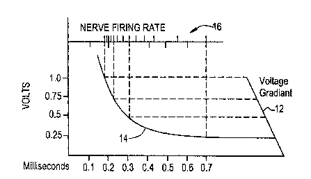
Figure 1~1 shows a graph illustrating a gradient
electrical field 12 imposed on a linear matrix of nerve
fiber endings.' The graph illustrates a strength duration
curve 14 in (relative) volts per milliseconds. The
strength-duration curve is a plot of the threshold
intensity just capable of exciting an axon and its
relationship to the duration of the stimulus current.
The strength duration curve expresses the relation
between least strength of an applied current and least
time during which the current must flow in order to reach
a threshold for excitation. There is a minimal current
density below which excitation does not occur. The
-2 9-
CA 02288314 1999-11-02
P-12481.JSS
ag\f:\work\030\P12401\SPEC\P124~1.JSS
strength duration curve does not show the effects of
subthreshold st.i.mu:l.ils upon excitability. The
subthreshold current flow may advantageously be used in a
preferred embodiment of the present invention as a means
of adjacent channel overlapping or to enhance the
background state of nerve activity.
I~'igure lA further shows at 16 a firing sequence
of a group of nerve fibers when a stimulus pulse is'
applied which has a potential gradient that causes the
stimulus amplitude at each nerve fiber to be different
than its adjacent nerve fibers.
figure 1B shows a two dimensional graph
illustrating one channel of a gradient probe and the
gradient field.-~igure 1B shows the location of the
15 active and ground electrodes 20 and 22 for a single
stimulus channel. The active electrode and each of its'
associated ground electrodes produce a gradient field
between the electrodes and for a small distance above the
electrodes. The gradient probe is placed such that the
20 nerves to be stimulated are in this gradient field either
between the electrodes or immediately adjacent to the
electrodes. rigure 1B also shows the gradient field 24 in
terms of a voltage. The illustrated range for the voltage
is exemplary and does not represent actual voltages used.
25 Those skilled in the art will appreciate that nerve
fibers can be stimulated with as low as 100 millivolts.
16 CHANNEL STIMULATOR CIRCUIT
A 16-channel system using a 200 Hz repetition
rate produces a channel-s~n~i.tch.9.ng frequency of 3, 200 Hz.
-3 0-
CA 02288314 1999-11-02
P-12481.JSS
ag\f:\work\030\P129D1\SPEC\P124~1.JSS
It requires an average of 7.5 nerve fibers streaming~per
channel to achieve a 24 kHz neuron-carrier frequency.
Amplitude modulation of the pulse stimulus (to provide
the sensation of sound) is transformed into frequency
modulation of the neuron-carrier frequency. Precision in
tracking the strength-duration curve is not required as
only a small portion of the strength-duration curve is
utilized. With this number of channels, the streaming
time per channel is only 0.25 ms and the variation of
slope during that time is small.
Figure 2 is the schematic of the clock,
modulator and signal generator. Its function is to
generate a sequence of bi-phasic pulses and the
appropriate modulation of a portion of the bi-phasic
I5 pulses . .
Starting at the left of Figure 2 are the
terminals 30a and 30b for the power source of +6 volts
and -6 volts. Across both the -H and - terminals are
filter capacitors C1 and C2 to provide stable voltages
free of shifts due to variations in current requirements.
The Schmitt trigger IC1 (1/6 of a 74C14) along with R1
and C3 form an oscillator, which provides the clock of
the system. The values of R1 and C3 determine the clock
frequency. The output of the Schmitt trigger drives IC2 a
4 bit binary counter (74C93). This counter divides the
clock signal by 16.
The two least significant digits of the output
of the counter IC2 drive the least significant inputs of
a 4028 BCD to Decimal Decoder IC3. The 2 most significant
inputs are grounded malting the 4028 in effect a 2 digit
-3 I -
CA 02288314 1999-11-02
P-12481.JSS
ag\f:\work\030\P12401\SPEC\P124A1.JSS
Binary Decoder. The four outputs representing logic
values 0 through 3 (4 separate states) drive the 4001
Quad 2-Input NOR Gates IC4. The 4 outputs of the NOR
Gates are bi-phasic signals that swing between the power
supplies rails of +6V & -GV and are shifted in phase from
each other by 90 degrees (see Figure 2). These outputs
drive 220IC resistors R 2, 3, 4. &5. These outputs will be
summed with the modulation signal.
At the bottom right of Figure 2, the modulation
input goes through a 10K resistor R14 to the input one
half of a 4052 dual 4-Channel Analog Multiplexer IC5. The
channel selection inputs of IC5 are in parallel with the
inputs of the 4028 IC3. The outputs of IC5 are modulation
signals delayed by 90 degrees from the outputs of IC4.
The outputs of IC5 drive 220K resistors R 6, 7, 8, &g
which sum with the outputs of R 2, 3, 4, &5. The timing
causes the modulation to only be imposed on the last half
components of the bi-phasic pulses. R14 is a resistor in
series with the modulation signal. It provides a lOK
input resistance to IC5 from the modulation source.
The outputs of the 4052 also go through
resistors R 10, 11, 12, &13 to electrical ground. Their
function including R14 is to lceep the impedance
substantially constant on the input to resistors R 6, 7,
8, & 9 so that the value of the summed outputs remains
substantially independent of which channel IC5 has
selected. There are three outputs from this circuit. At
the bottom left is the 4-digit ADDRESS BUS that is driven
by the outputs of IC2. At the right is the ST~NAL BUS
containing the 4 phase shifted bi-phasic analog stimulus
-32-
CA 02288314 1999-11-02
P-12481.JSS
ag\f:\work\030\P12481\SPSC\P129B1.JSS
signals including their modulation, and at the bottom
center is the ramp control signals. At the bottom right
of center are the RAMP CONTROL outputs.
Figure 3 is the schematic of the ramp
generator. At the left of the figure are the three
control signals that come from the ramp control of Figure
2. The A line drives a control line. of a Bilateral~Switch
4066, IC7 and through an inverter IC6 to a second control
line of IC7. The phase A and phase B signals coming from
Figure 2 charge capacitors C4 and C5 through resistors
R32 and R15. When IC7 switches are open, a voltage ramp
occurs. IC8 and IC9 are operational amplifiers each
having a positive gain of 11 due to the negative feedback
through resistor networks R16 & R17 and R18 & R19.
Resistors R20 and R21 introduce positive feedback causing
the ramp on C4 or C5 to produce at the output of the
amplifiers a curved up ramp similar to the curve of the
strength duration curve. R22 and R23 sum these ramp
output signals from IC8 and IC9 on to the SIGNAL BUS with
the A and B signals from Figure 3. IC10 and IC11 are
operational amplifiers connected with a gain of -1. The
resistors R24 & R25 and R26_& R27 determine this.
Resistors R28 and R29 reduce DC drift by lceeping the two
inputs of each amplifier at the same impedance. R30 and
R31 sum the outputs of IC10 and IC11 to the STGNAL BUS
lines C and D. Resistors R22 and R23 sum the outputs of
IC8 and ~IC9 to the A & B lines of the SIGNAL BUS.
Figure 4 is the 16 Channel Multiplexer. The
ADDRESS BUS lines from Figure 2 connect to the address
bus input at the bottom left of the figure. The ADDRESS
-33-
CA 02288314 1999-11-02
P-12481.JSS
a9~f:\work\030\P12401~SPGC\P124~l.JSs
BUS drives the address input lines of IC12, a 74C154 4-
line to l6-line Decoder. The output of the Decoder IC12
has 16 lines (0 through 15) that turn on one at a time in
sequence in a cyclic manner. The first 4 lines 0 through
3 go to the input of a 4-input NAND Gate IC13A (1/2 of a
4012 Dual 4-Input NAND Gate IC13). The output of the
IC13A NAND Gate is high through the first 4 positions of
the 16-line decoder. In a similar manner the lines 1
through 4 of IC12 go the inputs of the IC13B NAND. Its
output will be delayed by one count from IC13A and so
through the eight 4012 ICs IC13 through IC20. Note that
this is done in a cyclic manner so that the output of the
gate IC20B starts one clock pulse before the output of
IC13A. These outputs which last 4 cloc)c pulses long and
IS are overlapped by three clock pulses from its adjacent
channel control Triple 2-Channel;Analog Multiplexers ICs
21A, B, C through IC26A.
The multiplexer when on selects the bi-phasic
Signal A to connect to its output when turned on and
signal ground when turned off. Iri a similar manner IC21B
switches Signal B, IC21C switches Signal C, IC22A
switches Signal D, IC24B switches Signal A and so forth
through IC26A and then back to IC21A. When the switches
are not connected to one of the Signal A, B, C, D lines
they are grounded to prevent crosstalk and prevent
leakage currents. The outputs of the Multiplexer switches
are of low impedance and provide a voltage output.
Resistors R33 through R48 change the voltage output into
a current to drive.the nerve probe. Their resistance
value is substantially higher than the resistance of the
-34-
CA 02288314 1999-11-02
P-12481.JSS
ag\f:\work\030\P12481\SPEC\P12481.JSS
nerve probe electrodes thereby insuring that the nerve
drive is relatively independent of the probe resistance
path to the nerves.
Fine adjustment of output current can be done
by varying the power supply voltage which has a small
effect on the cloc)c frequency or by placing a shunt
variable resistors across each Signal line A, B, C, &D tc
signal ground which will reduce the voltage swing of
these points and therefore reduce the current drive to
the nerve. Each variable resistor effects only 1/4 of the
16 outputs, therefore the 4 variable resistors are
ganged.
Figure 5 shows the waveforms of the 16
channels. As shown in the figure, each channel is delayed
1S by 90 degrees of a complete pulse cycle. The amplitude of
the stimulus pulse is set so that nerve streaming (or
firing) starts at the start of the slope compensation.
Note that the slope compensation may occur at the
beginning of the stimulus pulse (not shown in Figure 5)
or in the second portion of the stimulus pulse (as shown
in Figure 5. However, the modulation.does not occur until
nerve streaming is in place.
Figure 6A shows the strength-duration curve 40
with the stimulus pulse 42 crossing the.:~txwn:~t,1-ciuration
curve and the compensation added to the stimulus pulse to
generate a constant rate of tiring of the nerve fibers.
Figure 6B shows the audio modulation 44 superimposed on
the last portion of the stimulus pulse. Both figures show
the stimulus in a positive direction. This is only for
-3 5-
CA 02288314 1999-11-02
P-12481.JSS
ag\f:\work\030\P12981\SPEC\P12481.JSS
simplicity and does not necessarily indicate the polarity
of the stimulus pulse.
Figure 7 is a drawing of a 16-channel probe.
This is connected to the channel outputs of Figure 4.
Figure 15A shows a 4-channel probe. Its design is
typical of 4-channels of a 16-channel probe.
4 CHANNEL STIMULATOR CIRCUIT
The 4-channel analog system is a configuration
with the preferred minimum number of channels. Therefore
it requires a preferred maximum number of streaming nerve
fibers to be stimulated per channel and a preferred
maximum of compensation for the strength-duration
characteristics of the nerves. To achieve a 24 kHz
neuron-carrier or streaming frequency let us assume a
repetition rate of 200 pulses per second times 4 channels
results in a total of 800 channel stimulus pulses per
second. If 30 nerve fibers are activated in uniform
sequence per channel, a 24 kHz neuron-carrier frequency
will result. Amplitude modulation of the pulse (to
provide audio sensations) then in effect transforms into
a frequency modulation of the neuron-carrier frequency
(more or less than 30 nerve fibers being fired per
pulse) .
. Figure 8 is a block diagram of a 4-Channel
System. At the left is the microphone driving an audio
amplifier and limiter/automatic gain control. The output
of the audio amplifier drives the external transmitter.
The internal receiver drives the Cloc)c-Modulator,
Stimulus Generator & Strength Duration ramp generator.
-3 G-
CA 02288314 1999-11-02
P-12481.JSS
ag\f:\work\030\P12981\SPEC\P12481.JSS
The output of this module is fed through an attenuator to
a 4-channel multiplexer. The output of the multiplexer
then drives the probe.
Figure 9 is the circuit of the audio
preamplifier, clock, and sequencer. To the bottom left of
the figure is the Clock Oscillator 60
IC27 i
.
s one
section of a 4093 used as a Schmitt trigger. R48 and R49
. provide feedback to the input. C6 along with the sum
f
o
R48 and R49 determine the clock frequency. R49 provides a
means of adjusting the clock frequency. The output of the
clock drives the input of a 4-bit 74C393counter IC28 and
also to the SD Ramp generator 62. The output of IC28
drives a 4-Line tol6-Line Decoder, IC29. At the right
bottom of the figure is the wiring of 4093 Quad 2-Input
IS Nand Schmitt Triggers wired to build, Set-Reset Latches.
At,the top left of the figure are 6 4093~s, IC30 through
' IC35 wired as shown to provide Set-Reset Latches. The
first Latch IC30A is set on position 0 of the IC29
output. The second Latch IC30B is set on position 4, the
third Latch IC31A at position 8 and the 4tt'Latch IC31B
on
position 12. Tn a similar manner the first L
t
h i
a
c
s
reset on position 5, the second Latch is reset on
position 9, the third latch is reset on position l3 and
the fourth Latch IC31B is reset on position 1. The output
25 of these tour latches is fed through resistors R50, R52,
R54, and R56 to be summed with the audio, modulation.
In the lower center of the Figure 9 is the
microphone input 64 driving a closed loop amplifier IC36
with a gain of about 80. The ratio of R58, the impedance
30 of the microphone and R59 determine the gain. C7 AC
-3 7-
CA 02288314 1999-11-02
P-12481.JSS
ag\f:\work\030\P12481\SPGC\P12481.JSS
couples to the next stage through a volume control R60.
The value of C7 may be selected to provide preemphasis..
IC37 adds an additional gain of 3 determined by the
values of R61 and R62. The output of amplifier IC37 is
the audio signal. It is fed into 4 single pole double
throw CMOS switches IC39B, IC39C, IC40A and IC40B.
Latches IC32A, IC32B, IC33A and IC33B control these
switches. The arm of the switches is connected through
resistors R51, R53, R55, and R57 to sum with the channel
stimulus outputs. Latches IC32A, IC32B, IC33A and IC33B
control the timing of the switches. TC32A sets on IC29
position 1 and resets on position 5, IC32B sets on
position 5 and resets on position 9. IC33A sets on
position 9 and resets on position 13. IC33B Sets on
15 Position 13 and resets on position 1. The summed outputs
for channels 1 through 4 are fed into CMOS switches
IC38A, IC138B, IC138C and IC139A. The output of these
switches selects either the summed outputs of channels 1
through 4 or a ground reference level.
20 At the lower left of Figure 9 are 4 outputs 66
going to the SD compensation circuit. These come from
IC41 and IC42. IC43 a 74C08, an AND gate, drives their
set and reset times as follows. RESET CH1 sets on
position 0 and 6 (low output sets the latch) and resets
25 on positions 5 and 9. In a similar manor RESET CH2 sets
on positions 5 and 9 and resets on positions 8 and 14.
RESET CH3 sets on positions 8 and 14 and resets on
positions 1 and 13. RESET CH4 sets on positions 1 and 13
and resets on positions 0 and 6.
-3 8-
CA 02288314 1999-11-02
P-12481.JSS
ag\f:\work\030\P12481\SPEC\P12981.JSS
Figure 10 is the schematic of one channel of
the four channels of the Strength-duration compensation
circuit. At the bottom left the inputs from the clock and
reset signals from Figure 9 enter. The clock signal
enters the cloc)c input of a 74C393, TC45 and the eloc)c
input of the 74C174, IC46. TC45 is held at zero by the
reset/clear signal. When the reset signal stops, the
counter starts counting. IC46 prevents counting timing
errors by capturing the counter's value after any ripples
have settled. The output of the IC46 register drives two
digital to analog converters comprised of 4053 CMOS
switches IC~7, IC48, IC49, and IC50. These switches drive
two binary ladder networks LR1 and LR2. At the top left
of Figure 10 the input signal from Channel 1 of Figure 9
is fed into a buffer amplifier IC53 which drives first
ladder Switches IC47 and IC48. The output of LR1 is fed
into a buffer amplifier TC51, which drives the reference
of the second DAC switches IC49, and IC50. In this manner
a square law curve is generated to mirror the strength
duration curve. This curve which is generated by the
Channel 1 signal also has the audio modulation generated
in Figure 9; A second buffer amplifier IC54 feeds the
Channel 1 signal through a 200K resistor R63 to the
output of the second DAC. The outputs are summed and fed
into a buffer amplifier IC52. This circuit for
compensation for the SD curve is repeated for each of the
four channels as shown in Figure 11.
At the bottom center of Figure 11 is a block
called LATENCY LOGTC 70. When this is activated the
pulse to each channel is shortened to the :l.at-..e~.~.cy time,
-3 9-
CA 02288314 1999-11-02
P-12481.JSS
ag\f:\work\030\P12481\SPEC\P12481.JSS
the time before the first nerve fiber is activated in a
channel. It allows only one channel to be activated at a
time. This is to allow for the adjustment of each channel
stimulus amplitude to have its proper latency time and is
also used to establish the strength duration
characteristics for each nerve group during testing.
Figure 12 is the schematic of the LATENCY PERIOD GATE
logic. The signals from Figure 9 lower right drive IC53 a
74C08 AND gates. 100K resistors R64, R65, R66 and R67
ground one input of each AND gate. When SW1 is in the 1
position the input to IC53 which was held low by R64 goes
high allowing the signal from TC44 to pass through to the
output of IC53. In this manner each channel may be
selected by SW1. When SW1 is in the OFF position a high
15 signal is given to IC54 which causes the outputs of IC54
a 74C32 to turn on. The output of TC54 drives the analog
switches IC55, and IC56 to select ground and the
respective signal channel output or allows all channels
to feed through.
20 Figure 13 is the circuit that adjusts the
amplitude of each channel. IC57 is a .Quad Schmitt two
input gate that in combination with R69 and C7 generates
a clock. The clock is enabled when either the UP switch
SW2 or the DOWN switch SW3 is activated. When the down
25 switch~is activated, a low signal drives the up down
counters ICSa and IC59 down inputs. In this manner, the
counter,will count up or down when commanded. Only 6 bits
are used of the possible 8 from the up/down counter. The
diodes D1 through D8 are used to prevent the counter from
30 rolling over. When the count reached full scale it will
CA 02288314 1999-11-02
P-12481.JSS
ag\f;\work\030\P12981\SPEC\P129B1.JSS
not carry over to 0, and also when counting down to 0 it
will not roll baclc to full scale. The output of the
counters IC58 and IC59 drive four DACs configured as for
the SD compensation circuit. This circuit in effect
replaces a four-ganged potentiometer. The inputs to the
four DACs are the output four signal channels of the
J.~.ttE_Tl~~~r period gate Figure 12.
Figure 14 shows the waveforms for each of the 4
channels along with their modulation component. This
figure shows an overlap of 0.2 oz- 0.:~ milliseconds
between channels and the superimposing of the modulation
and compensation of the strength-duration characteristics
of the nerve fibers on all but the first 0.2 or 0.3
milliseconds of each channel. Each channel stimulus pulse
IS is bi-phasic to avoid introducing a DC component in the
system. The modulation is only on the nerve-firing
portion of the pulse. Since the modulation has an average
value of zero over time, it is not necessary to modulate
the portion of the stimulation pulse following i~he
modulation. The portion of the stimulation pulse that
follows the modulation is an inversion and results in an
average DC value of 0. Not shown in this figure but
shown in Fig. 5 as typical is the background state of
nerve activity when no sound is present.. This background
state when modulated results in the perception of sound.
Figure lSA shows a four-channel probe 80. The
conducting area of the electrodes is vertical producing a
gradient field between the electrodes and providing a
maximum surface area for each electrode. Tn this way the
3U contact surface area is not determined by the closeness
-41-
CA 02288314 1999-11-02
P-12481.JSS
ag\f:\work\030\P12481\SPEC\P12481.JSS
of the electrodes and an accurate gradient field is
produced.
The distance between ground electrodes can be
as srnall as 20 microns and over 200 microns. The hair
cells are spaced typically 10 microns. Twenty-micron
spacing allows only 1 row of hair cells between the
active electrode and its associated ground. However if
the probe is tilted so that the hair cells are staggered
between the active and ground electrodes, streaming will
occur. Even though the hair cells are non-functional in
the profoundly deaf, the location of the hair cells is an
indication of the location of the ends of the nerve
fibers transmitting sound sensations to the brain. Behind
the ground and active electrodes is a layer of
insulation. This is to avoid producing an electric field
on the backside. Behind the insulator is an additional
ground plate to increase to a maximum the ground area. A
maximum ground area is desired as it lowers the contact
impedance of the ground to the conducting fluid and
provides a gradient field that minimizes channel
crosstalk. Also, not shown in the Figure, insulating
material may be placed at the side ends of each channel
to prevent current flow out the side ends.
Figure 15B shows a four-channel probe located
near the Spiral Ganglion. As in Figure 15A, the
electrodes are mounted perpendicularly to the gradient
field. .The diameter of the probe at its largest point is
about 2 mm, and the diameter of each electrode at its
largest point is about 1 mm. The distance between ground
electrodes is between 0,5 mm and 2 nun. The probe
-42-
CA 02288314 1999-11-02
P-12481.JSS
ag\f:\work\030\P129B1\SPGC\P129A1.JSS
electrodes are mounted in a flexible insulation structure
allotaing the probe to form to the shape of the Scala
Tympani or the Scale Vestibuli. The length of the probe
area housing the electrodes is between 2 mm and 8 mm. In
systems with more than 4 channels, the spacing between
ground electrodes would be less.
THE DIGITAL SYSTEM
The limit of this system leads to a system
where only 1 nerve fiber is stimulated per channel and
the system becomes purely digital. Again to achieve the
24 kHz carrier frequency in the digital system, where the
repetition rate of firing an individual nerve fiber is
200 pulses per second, 120 channels are required. (120 X
200 = 24,000). In this digital system, rather than track
the Strength-duration curve for each channel, as done in .
the analog systems, a high amplitude stimulus pulse is
utilized to place the tiring of the nerve fiber on a
steep portion of its Strength Duration curve. This
minimizes the activation time differences between
channels. The electric field is restricted to only 1 or a
small constant: number of nerve fibers, which appear to
fire simultaneously, producing the 24 kHz neuro-carrier
frequency. In this digital system, modulation is
accomplished by frequency modulating the carrier
frequency. No amplitude modulation of the pulse stimulus
is required. It becomes apparent from this that in a
system that is in the transition region between analog
and digital both amplitude and frequency modulation may
be used to advantage.
-43-
CA 02288314 1999-11-02
P-12481.JSS
ag\f:\work\030\P12981\SPEC\P12901.JSS
Figure 16 is a bloc)c diagram of the digital
system. At the left of the figure is the external unit
102. It consists of a microphone, audio amplifier,
limiter/automatic gain control, oscillator, frequency
modulator, loop antenna and a power source. In the center
of the figure is the internal unit 104, a loop receiving
antenna, diodes to provide both positive and negative
voltage, voltage regulators and a 128 position
counter/decoder and individual latches for each channel.
To the right of the figure is the probe 106 that is
placed near to the nerve fibers that conduct sound to the
brain.
Figure 17 is one version of the external unit.
To the left of the figure is a capacitor microphone M1
connected to the input of the Schmitt IC62 with feedback
through resistors R72 and R73 forming a frequency-
modulated oscillator. R73 is variable to adjust the
center frequency. The output of the oscillator is divided
by 2 in IC63, a 74C93 counter. The output of IC63 is
buffered by IC64 to prevent capacitive loading on the
counter output. The output of the buffer IC64 drives IC65
a MOSPOWER HALF-BRIDGE DRIVER Si9950. The output of TC65
is a low impedance switch that switches from one power
rail to the other. The output is fed through C9 to the
Loop Antenna L1. Capacitor C9 resonates with the
inductance of the Loop Antenna forming a tuned circuit.
Capacitor C8 is across the power connections of IC65. The
layout is such that there is a minimum of area within the
current path as the resonate currents through the loop
-44-
CA 02288314 1999-11-02
P-12481.JSS
ag~f:\work\030\P129A1\SPEC\P124p1.JSs
can be high and any areas outside the Loop Antenna will
reduce efficiency.
Figure 18 is the internal digital system unit.
At the top left of the figure are the loop antenna L2 and
its tuning capacitor ClO. The output of the loop antenna
goes through diodes D8 and D9 to produce + and -
voltages. Capacitors C11 and C12 filter the DC voltages.
Voltage regulators vRl and VR2 regulate the voltages. C13
and C14 provide stability to the voltage regulators
outputs. R74 is connected to the Loop antenna output to
provide a cloc)c to the implanted system. Diodes D10 and
D11 limit the voltage swing at the input of IC66 a
Schmitt trigger. IC64 provides the clock signal to the 7
bit counter decoder IC67. The 128 positions of the
15 counter IC67 (0 through 127) drive set-reset latches IC68
through IC95 formed by 74C00 CMOS gates.
' As shown in the lower left of Figure 18, these
latches are set on a given number N, with the first latch
reset at N+4 and the second latch reset at N+8.
20 Subsequent latch pairs are shifted one count down as
shown in the drawing. The outputs of.the first latch pair
goes into a 4053 IC196A. When the switch IC196A is OFF,
the output of the switch is at ground or zero potential.
When the switch is ON the output of the.first latch is
25 connected to the output. This will occur for one complete
cycle of the first latch. In this way the average
potential of a given channel will be 0. The output of
these switches have their voltage changed into a current
through resistors the same as R73 on channel 1 and also
-45- ,
CA 02288314 1999-11-02
P-12481.JSS
ag\f:\work\030\P12481\SPEC\P12481.JSS
through capacitors such as C15 to further ensure no long
term DC component.
Figure 1.9 shows the waveform of the individual
channels of the digital system. The circles on the
waveform indicated the time that the nerves tire. The
delay between channels is 40 microseconds. The amplitude
of each stimulus pulse is such that'the exc.itation~tzme
of a nerve fiber will occur on a steep portion of the
strength duration after 120 microseconds and the stimulus
pulse will last beyond the excitation of its nerve fiber,
in this drawing 160 microseconds. The repetition rate of
each channel is 5.12 milliseconds or about 5 time
constants, which allows the recovery of the nerve to
about 10 of its initial condition before stimulus. In all
IS systems both analog and digital a carrier of about 25 kHz
is used only as an example. Higher frequencies would
require a higher stimulus amplitude which would cause a
higher streaming rate and would provide greater frequency
response of the modulation. It is also recognized that as
with any carrier system the audio modulation bandwidth
must be restricted to less than 1/ t.ill'tc~s the carrier
frequency.
PROCEDURE
The procedure for implanting the device into a
human ear is as follows:
The placement of the gradient probe is critical
and requires precise placement fox optimum performance.
With an adult patient who has heard in the past the probe
is placed while the patient is alert. Using a local
-46-
CA 02288314 1999-11-02
P-12481.JSS
ag\f:\work\030\P129B1\SPEC\P12901.JSS
anaesthetic the probe is moved into place by having it
activated and the patient indicating when he hears
intelligible sound. Then for exact placement each channel
is stimulated alone to establish that each channel
requires about the same stimulus intensity to produce the
sensation of sound a.nd t:o vPr..i.fy th.P stir ength-ci.i.~ra.t-;.ox~
r:'~;aractc-:r.~s.7t~:ir~s. A second time the patient is as)ced to
confirm that his hearing is normal and then the probe is
fixed permanently in place. During this procedure a jig
that is mounted to t'he patients head is used to hold the
probe so that motion of the head will not effect the
location of the probe in relation to the nerve fibers.
With patients who have not heard in the past
the probe is located as above except the last step is to
15 confirm that a minimum of sound is heard when no external
sound is present and sounds are comfortable when
externally generated.
For children who are unable to provide direct
assistance, other means of establishing the presence of
sound sensations through measurement of nerve activity at
a higher level or brain activity may be used. One method
is through the measuring of nerve activity in the
cochlea.
The method of the present invention directly
25 stimulates nerve fibers of the audio transmission portion
of the 8"' nerve with electrical signals representative of
sensed audio sounds in sequence, thereby imparting the
sensation of hearing to a deaf patient. The method
comprises implanting a receiver with a loop antenna and
with connections to an electrode probe, comprised of an
CA 02288314 1999-11-02
P-12481.JSS
ag\f:\work\030\P12481\SPEC\P124~1.JSS
array of electrodes formed to produce multiple gradient
fields in the patient, on the audio portion of the Stn
nerve and generating an electrical signal representative
of sensed audible sounds. An electrical signal is
divided into time multiplexed channels whereby each
multiplexed channel is connected to a corresponding
gradient probe channel and contains the audible
representation of the entire audio spectrum and means for
limiting the audio spectrum. Each channel is processed
to produce a bi-phasic stimulation signal that overlaps
its adjacent (in time) channel bi-phasic stimulation
signal but does not overlap its component that is
representative of audible sounds.
The method further comprises aligning an
15 external transmitter,/wer:E~iwvx~~.~ loop antenna with the
implant receiver] transrnittinc~ loop antenna such that
there is a distance at least'equal to the thic)tness of
the patient's skin separating the external antenna from
the internal antenna thereby providing a means of
20 transmitting both power and audible sound representations
to the implant receiver, and locating the gradient probe
in proximity to the nerve fibers that transmit sound
sensations to the brain. Further, the method comprises
compensating for motions of the patient's head during
25 placement of the gradient probe; and fixing in a
permanent manner the gradient probe.
While there have been shown embodiments of the
invention, it will be understood that changes and
modifications may be made to the methods and devices
30 shown herein by those skilled in the art and it is,
_~8_
CA 02288314 1999-11-02
P-12481.JSS
ag\f:\work\030\P129B1\SPEC\P12981.JSS
therefore, intended that the appended claims cover all
such changes and modifications as fall within the true
spirit and scope of the present invention. In the
circuits described above standard well known components
are shown. This is to provide specific examples of how
detailed functions may be effected. It does not suggest
that programmable gate arrays, microprocessors or other
components are excluded. In fact devices such as Intel's
8XL51FX COMMERCIAL/EXPRESS LOW VOLTAGE CHMOS SINGLE-CHIP
8-BIT MICROCONTROLLER are an excellent choice to
mechanize the functions of the invention. When operated
with a clocJc frequency of 3.5 MHz it draws less than 6
mA.
Fig. 22 is a system bloc)c diagram including the
use of all of these devices. At the top left of the
figure is a sketch of the external module 120 to be .worn
by the patient. It is designed to be worn behind the ear
in a manner similar to some conventional hearing aids. It
houses a high-energy rechargeable battery as a power
source. The unit, when not in use, can mount in a charger
showed beneath the unit. The external module has a volume
control, a null background tone adjustment, a power
switch and a microphone located in the unit behind a
small hole. The antenna coil is connected to the unit
through a small cable and mounts adjacent to the implant
receiver coil. To the right of the external module
pac)cage ~ is a blocJc diagram 122 of the circuits . The
microphone drives the automatic gain control circuit. The
volume control sets the input to an analog to digital
converter. Above the AGC block are the up and down
CA 02288314 1999-11-02
P-12481.JSS
ag\E:\work\030\P12981\SFEC\P12901.JSS
controls which drive an up/down counter. This is a fine
trim of the stimulus level. This value plus the output of
the DAC is formatted to feed the modulator, which
superimposes the data onto the oscillator output and is
fed to the antenna.
Located beneath the external module and charger
is a sketch of the physician's office computer module 124
consisting of a lap top computer with a microphone, a
transmitter/receiver and software to perform the
lU following functions:
1) Establish a bi-directional communication link between
the external computer and the implant computer,
2) adjust the channel selection rate (or channel
15 I frequency) , stimulus amplitude for each channel boi:~u
independently and in a ganged manner.
° 3)' Adjust the compensation for the strength-duration
curve. This adjustment is in the form of a computer
table. It establishes a time constant curve that can be
20 trimmed at all points of the curve to null out the
variations in the nerve activity carrier. This curve
interacts with the stimulus amplitude adjustment as its
values are in terms of. percentage of stimulus amplitude.
The time axis of the table is independent of the channel
25 selection rate.
4) Adjustment of both audio (coarse) level and soft
start speed.. The soft start/stop function causes the
background carrier to gradually turn on or off with a
minimum of annoyance to the user.
-50-
CA 02288314 1999-11-02
P-12481.JSS
ag\f:\work\030\P12981\SPEC\P129B1.JSS
5) Adjust the number of channels to be used. Four are a
minimum and eight are a maximum. It also selects which
channels of the probe will be used. First the physician
scans each channel and establishes its functionality as
to sensitivity, and.strength-duration characteristics. In
the case of the choice of 4 channels to be used, then the
physician selects which channels of the probe will be
used. All unused channels are grounded to the common
return electrodes. In the case of a 6-channel system the
best 6 probe channels are used. During this selection
process the electrode matrix switch remains.on the
selected channel electrodes and all other channels are
grounded. Figure 22C shows the selection of 4 channels of
an 8 channel probe.
15 Figures 22A, 22B and 22C are the screen
displays for the various functions computer screens.
In the center of Figure 21 is the block diagram
130 of the implant unit. To the far left of the block
diagram is the receiving/transmitting loop antenna. This
20 feeds to the receiver which develops a voltage that is
then regulated and provides component failure protection,
power up and down of the embedded microprocessor, high
voltage for non-volatile memory writing and a soft start
and soft shut down of irhe probe stimulus. A second output
25 of the receiver is the serial data output. This feeds a
data decoder and then the microprocessor. Both command
signals.and audio data enter the microprocessor. The
pror~ram~:d fumcr_~ ion values of the microprocessor are set
into a non-volatile memory. Eight digital to analog
30 converters (these may either be of an analog type or can
-$1-
CA 02288314 1999-11-02
P-12481.JSS
ag\f:\work\030\P129A1\SPEC\P12401.JSS
be produced by pulse width modulation as subthreshold
stimulus acts in an additive way and has an effect of
increasing the excitability of nerve cell membranes)to
drive eight current sources of which four to eight may be
used. The outputs of. these current sources produce both
negative and positive currents to establish an average DC
potential of zero. These current source channels are then
selected by the, electrode switch matrix to feed though
capacitors, reducing the possibility of a DC component
residue, to the probe electrodes.
As those of ordinary s)cill in the art will
understand, the present invention may be embodied in many
different specific ways, and the specific details
disclosed herein are only examples of how to practice the
IS invention. For example, many alternate block and circuit
diagrams are the equivalent of the example diagrams shown
in the drawings, and may be used to perform this
invention. Also, the electrical circuits needed may be
manufactured as integrated circuits or they may be
embodied in a microprocessor, or a combination of
integrated circuits and microprocessor may be used. In
fact, a microprocessor, because it may be programmable
and because of its small size, may be a particularly
advantageous device for use in the invention.
v~Thile it is apparent that the invention herein
disclosed is well calculated to fulfill the objects
previously stated, it will be appreciated that numerous
modifications and embodiments may be devised by those
claims cover all such modifications and embodiments as
-52-
CA 02288314 1999-11-02
P-12481.JSS
ag\f:\work\030\P124B1\SPEC\P12981.JSS
fall within the true spirit and scope of the present
invention.
S
-SJ-