Note: Descriptions are shown in the official language in which they were submitted.
CA 02288381 1999-11-02
OPEN HOLE ZONAL ISOLATION AND CONTROL
BACKGROUND OF THE INVENTION
Field of the Invention
The invention relates to the oil field industry. More particularly, the
invention
relates to hydrocarbon production systems in highly deviated (>55 deviation)
wellbores.
Prior Art
Highly deviated or horizontally disposed wellbores have been employed in
growing numbers in recent years to access oil reservoirs not previously
realistically
productible. In an open hole completion however, and especially where there is
water
closely below the oil layer or gas closely above, highly deviated or
horizontal wells
are much more difficult to produce.
Pressure drop produced at the surface to retract oil out of the formation is
as its
highest at the heel of the highly deviated or horizontal well. In an open hole
well, this
causes water or gas coning and early breakthrough at the heel of (or any part
of) the
highly deviated or horizontal well. Such a breakthrough is a serious
impediment to
hydrocarbon recovery because once water has broken through, all production
from the
highly deviated or horizontal is contaminated in prior art systems.
Contaminated oil
is either forsaken or separated at the surface. Although separation methods
and
apparatuses have become very effective they still add expense to the
production
operation. Contamination always was and still remains undesirable.
Another inherent drawback to open hole highly deviated or horizontal wells is
that if there is no mechanism to filter the sand or formation solids prior to
being swept
up the production tubing, a large amount of solids is conveyed through the
production
equipment effectively sand blasting and damaging the same. A consequent
problem is
1
CA 02288381 1999-11-02
that the borehole will continue to become larger as sand is pumped out. Cave-
ins are
common and over time the sand immediately surrounding the production tubing
will
plug off and necessitate some kind of remediation. This generally occurs
before the
well has been significantly depleted.
To overcome this latter problem the art has known to proppant pack the highly
deviated or horizontal open hole wells to filter out the sand and support the
bore hole.
As will be recognized by one of skill in the art, a proppant packing operation
generally comprises nmning a screen in the hole and then pumping proppants
therearound in known ways. While the proppants (such as gravel, ceramic beads
etc.)
effectively alleviates the latter identified drawbacks, water or gas coning
and
breakthrough are not alleviated and the highly deviated or horizontal well may
still be
effectively occluded by a water breakthrough.
To achieve zonal isolation, the art has known to proppant pack multiple stage
between pre-activated isolation devices (such as external casing packer (ECP)
etc.).
This operation is known to be complex, time consuming and at high risk.
Since prior attempts at enhancing productivity in highly deviated or
horizontal
wellbores have not been entirely successful, the art is still in need of a
system capable
of reliably and substantially controlling, monitoring and enhancing production
from
open hole highly deviated or horizontal wellbores.
SUMMARY OF THE INVENTION
The invention teaches a system that effectively creates a proppant pack on
both sides of a non-activated annular seal (NAAS), allowing the seal to be
activated to
set against a casing or open hole. More specifically, the proppant when placed
by the
system of the invention, skips over the NAAS and leaves virtually no proppant
around
the NAAS when the annular velocity is above critical settling velocity. The
beneficial
effects of the invention are obtained by causing the proppant to stall in an
area
upstream of the NAAS by preventing leak-off downstream of the NAAS. When
sufficient pressure builds in the proppant carrier fluid, due to flow
restriction caused
2
CA 02288381 2007-04-17
by the tightly packed proppant upstream of the NAAS, a valve opens upstream of
the
NAAS and proppant begins to pack the downstream section.
Accordingly, in one aspect of the present invention there is provided a
hydrocarbon production system comprising:
a borehole in a hydrocarbon containing formation;
a continuous, one stage, gravel pack having a plurality of isolated zones;
at least one annular seal located between at least two zones of said plurality
of
zones; and
a valve and seal located upstream of said at least one annular seal, said
valve
selectively allowing through passage of fluid from an annulus outside of a
pipe upon
which said at least one annular seal is located and to a space inside of said
pipe.
This invention allows the proppant placement in continuous pumping operation,
prior to activation of the AS devices. An additional benefit of the valve
structure of the
invention is that prior art limits on the length of a proppant pack are
avoided. More
specifically, because of the valves of the invention pump pressures do not
continue to
climb as they do in the prior art. Thus with the invention pressures do not
reach the
fracturing pressures, the avoidance of which limited prior art pack lengths.
3
CA 02288381 2007-04-17
BRIEF DESCRIPTION OF THE DRAWINGS
Embodiments of the present invention will now be described more fully with
reference to the accompanying drawing in which:
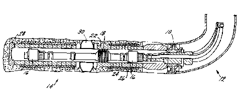
FIGURE 1 is a schematic cross section view of an open hole zonal isolation and
control system of the invention;
FIGURE 2 is a schematic cross section view of a proppants packing zonal
isolation embodiment of the invention where a secondary valve is closed;
FIGURE 3 is the embodiment of Figure 2 where the secondary valve is open;
FIGURE 4 is one embodiment of the valve for use in the embodiment of
Figures 2 and 3;
FIGURE 5 prior art pressure - time plot;
FIGURE 6 is the new invention pressure - time plot;
FIGURES 7-14 is another valve embodiment of the invention in a closed
position;
FIGURES 15-22 is another valve embodiment of the invention in an unlocked
position; and
FIGURES 23-30 is another valve embodiment of the invention in an open
position.
DETAILED DESCRIPTION OF THE PREFERRED EMBODIMENTS
Referring to Figure 1, in order to most effectively produce from a hydrocarbon
3a
= CA 02288381 1999-11-02
reservoir where a highly deviated or horizontal wellbore in an open hole
formation is
indicated, a proppants pack is ideally constructed. Moreover the proppants
packed
area is most desirably zonally isolatable. Such zonal isolation is, pursuant
to the
invention, by way of annular seal (AS) (i.e hydraulic packer, ECP or
mechanical
packer) at selected intervals or hydraulically isolated with composite
material or
cement (curable materials). To complete the system, a productionstring
including
flow control devices may be run into the hole, each zone being isolated by a
locator
and a seal. This production string may be omitted, allowing for subsequent
internal
zonal isolation in the life of the well. The various components of the system
are
illustrated in Figure 1 wherein those of skill in the art will recognize a
liner hanger or
sand control packer 10 near heel 12 of highly deviated or horizontal weilbore
14.
From liner hanger 10 hangs a production string that may include flow control
device
16 which may be hydraulic, mechanical, electrical, electromechanical,
electromagnetic, etc. operated devices such as sliding sleeves and seal
assembly 18.
Seal assembly 18 operates to create selectively controllable zones within
highly
deviated or horizontal wellbore 14. Seal assemblies 18 (in most cases there
will be
more than one though only one is depicted in Figure 1) preferably seal against
a
polished bore in the original proppants packing basepipe 22 which remains in
the hole
from the previous proppants packing operation.
Referring to FIGURES 2-4, an annular seal (AS) is employed to create the
zonal isolation. Traditionally, AS's are expanded (set against the proppants
pack
because proppants has settled thereover in the packing operation. The
proppants
between the open hole or casing and the AS is a leak path and is undesirable.
To
render the AS more effective, the present inventors have developed a system
which
effectively packs both uphole and downhole of an AS and deposits virtually no
proppants over the AS.
Referring to Figure 2, basic components will first be identified for frame of
reference. Washpipe 80 is located inside base pipe 82 which is screened 84, 86
in a
generally conventional manner. AS 88 is located centrally. In a preferred
4
CA 02288381 1999-11-02
arrangement a blank section 90 is located immediately downhole of AS 88 to
collect
overflow proppants from the uphole edge of the downhole screen. Without the
blank
section, the overflow would spill out over the AS and reduce the effectiveness
of the
invention. Washpipe 80 preferably includes a valve 92 with a seal. 94 just
downhole
of the valve 92, the seal spanning the annulus defined by the OD of washpipe
80 and
the ID base pipe 82. It should be understood that only a section _Qf the
portion of the
well being proppants packed is illustrated and that the proppants packing
activities of
pumping a loose slurry of proppants downhole through a crossover, through a
screen
and back uphole through the end of the washpipe should still be considered the
operation undertaken relative to the invention. The difference being shown in
the
figures and disclosed hereunder.
Again referring to Figure 5, the normal proppants packing action starts with
the a wave and leak-off fluid being drawn through screen 86 and to the end of
washpipe 80 (end not shown). As is known the a wave will continue to the
bottom of
washpipe 80 and then begin a(3 wave back uphole. The P wave propagates
proppants
deposition back up and over the top of the annulus around screen 86. As the (3
wave
nears the AS however, movement uphole thereof stops because there is no leak-
off
(necessary for deposition) above AS 88. The result -is that the proppants pack
96
below AS 88 is very tight and the pressure of the proppants carrier fluid
increases on
the area uphole of AS 88. Since there is no leak-off uphole of AS 88 no more
proppants is deposited. One should understand that there is no leak-off under
screen
84 because of seal 94. Without seal 94, leak-off would occur from under screen
84
and simply flow to the end of washpipe 80. Seal 94 prevents such flow and
creates
the above described condition.
As pressure increases in the annulus 100 to a preselected differential over
the
pressure in annulus 102, the valve 92 opens which in effect moves the end of
the
washpipe 80 to uphole of seal 94. Immediately upon opening of the valve 92
there is
a leak-off path (see flow lines 108 in Figure 6) from under screen 84 to
washpipe 80
and the (3 wave progresses thereto. Since the annular area 104 between AS 88
and the
5
CA 02288381 1999-11-02
open hole 106 is relatively narrow, the velocity of fluid traveling
therethrough is high
which prevents the deposition of proppants. Thus proppant is not deposited
until it
reaches screen 84 where leak-off is present and the velocity of the fluid
slows. Thus,
the (3 wave skips over the AS 88 and resumes over screen 84. Such skipping
will
occur in any location where the construction is as stated regardless of the
number of
AS's used. Because of the valve structures used, the pressure across the valve
actuator will always be balanced until the downhole section is packed up and
pressure
thereabove increases. This allows multiple units to be run simultaneously.
This will
be more clear from the following discussion of the valve embodiments.
The ASs can then be inflated conventionally with assurance that the OD
thereof will be in contact with the formation at open hole boundary 106 and
not a
segment of packed proppants. Hereby a reliable isolation between zones is
established.
Referring to Figure 4, one embodiment of the valve for the zonal isolation
system of Figures 2 and 3 is illustrated. For clarity, only the valve
structure itself and
seal 94 are illustrated. It should be understood that the intended environment
for the
valve is as shown in Figures 2 and 3.
Valve 92 includes flow port 110 which connects the interior of washpipe 80 to
the annulus 100 allowing fluid from annulus 100 to go to the washpipe 80. The
valve
will be initially closed by sleeve 112 having seals 114. Such position
(closed) is
preferably ensured by a shear out member 116 such as a bolt. The sleeve 112 is
connected to and operable in response to a piston 118 which rides in a bore
120 that is
bifurcated into chamber 120a and 120b by the piston 118. Provision is made to
allow
chamber 120a to "see" annulus 100 pressure while chamber 120b "sees" annulus
102
pressure. When annulus 100 pressure exceeds annulus pressure by a preselected
amount of about 20 to about 500 psi, the bolt 116 shears and the sleeve 112
shifts to
open port 110. In the drawing, chamber 120a is provided with the pressure
information through channel 122 and chamber 120b is provided with the pressure
information through channel 124. These are but examples of channels that can
be
6
CA 02288381 1999-11-02
employed and it is important to note only that the channels or other "pressure
sensors"
(computer sensors being an alternative where the sleeve is opened electrically
or
mechanically other than simply hydraulically) should be exposed to pressure on
opposite sides of the seal 94.
An additional benefit of the invention is that long runs of proppant material
can be installed without proppant fluid carrier pressure increase because of
the valves
employed in the invention. The pump pressure difference for the beta wave is
illustrated in Figures 5 and 6 where the invention (Figure 6) shows a saw
tooth
pressure pattern which keeps pressure low.
In another embodiment of the valve component of the invention, reference is
made to Figures 7-30, which broken up to Figures 7-14; 15-22; and 23-30
illustrate
three distinct conditions of the same valve. For frame of reference, seal 94
in this
embodiment of the valve of the invention can be found in Figures 12, 20 and 28
and
preferably is a bonded seal stack. A bonded seal stack is a phrase known to
the art
and requires no specific discussion. Such a seal arrangement is commercially
available from a wide variety of sources.
Referring now to Figures 7-14, the valve portion of the invention is
illustrated
in a closed position. This is the position for run in of the washpipe and it
is the
position in which the valve will remain until the proppants packing operation
causes
pressure to rise in the area uphole of seal 94 as hereinbefore described.
The valve is locked closed by lock piston 150 which prevents lock ring 152
from disengaging with groove 154 on washpipe 156. The lock piston is also
biased in
the locked position by spring 158 which is what preselects the pressure
differential
required to unlock the tool. Spring 158 is bounded by nut 159 which is
threadedly
attached to sleeve 160. One will note that annulus 161 (Figure 11) has been
left open
for receipt of the sleeve 160 and its actuation assemblies when opened. More
specifically, pressure in the area uphole of the sea194 is "seen" by the
uphole end of
lock piston 150; pressure downhole of sea194 is "seen" by the downhole side of
piston 150. Thus, the pressure downhole in addition to the spring 158 bias
must be
7
CA 02288381 1999-11-02
overcome for uphole pressure to unlock the tool. The pressure path for the
uphole
pressure is along the OD of the closing sleeve 160. Downhole pressure is
accessed
downhole of seal 94 at port 162 (Figure 13).
Referring to Figures 15-22, once the pressure uphole of seal 94 reaches the
preselected differential to that downhole thereof, the tool will be in the
condition set
forth in Figures 15-22, i.e, the lock piston 150 will move downhole off of
lock ring
152 which then disengages from groove 154. There is no longer anything holding
the
closing sleeve 160 closed and the same pressure that opened lock piston 150
will, in
conjunction with spring 168 which bears against spring stop 169, urge the
closing
sleeve 160 into the open position by shifting the sleeve downhole of the ports
164.
The open condition is illustrated in Figures 23-30 where the sleeve has moved
completely off ports 164 and has come to rest on land 170 with shoulder 172 of
sleeve
160 bearing thereagainst. Suitable seals 174 have been placed throughout the
tool to
contain pressure where desired.
The operable components noted are contained between a sleeve cover 180 and
the washpipe 156. Cover 180 is threadedly attached to seal sub 182 which then
is
attached via a acme thread to lower sub 184. One of skill in the art should
note the
lack of a seal 174 at the uphole junction of cover 180 and upper sub 188. This
is part
of the pressure path to the uphole area discussed above.
Since the provision of different zones and flow control devices in the
invention
allow the metering of the pressure drop in the individual zones, the operator
can
control the zones to both uniformly distribute the pressure drop available to
avoid
premature breakthrough while producing at a high rate. Moreover, the operator
can
shut down particular zones where there is a breakthrough while preserving the
other
zones' production.
After construction of one of the assemblies above described, and the washpipe
has been removed, a production string is installed having preferably a
plurality of the
seal assemblies with at least one tool stop mechanism to locate the seal
assemblies at
points where the basepipe is smooth and the inner diameter is not reduced.
Location
8
CA 02288381 1999-11-02
may also be assured based upon the liner hanger 10. The seal assemblies allow
different zones to be created and maintained so that selective conditions may
be
generated in discrete zones.
VVhile preferred embodiments have been shown and described, various
modifications and substitutions may be made thereto without departing from the
spirit
and scope of the invention. Accordingly, it is to be understood that the
present
invention has been described by way of illustration and not limitation.
What is claimed is:
9