Language selection

Search

Patent 2288462 Summary

Third-party information liability

Some of the information on this Web page has been provided by external sources. The Government of Canada is not responsible for the accuracy, reliability or currency of the information supplied by external sources. Users wishing to rely upon this information should consult directly with the source of the information. Content provided by external sources is not subject to official languages, privacy and accessibility requirements.

Claims and Abstract availability

Any discrepancies in the text and image of the Claims and Abstract are due to differing posting times. Text of the Claims and Abstract are posted:

  • At the time the application is open to public inspection;
  • At the time of issue of the patent (grant).
(12) Patent Application: (11) CA 2288462
(54) English Title: CONNECTING MEMBER FOR A PUMP
(54) French Title: PIECE DE LIAISON D'UNE POMPE
Status: Deemed Abandoned and Beyond the Period of Reinstatement - Pending Response to Notice of Disregarded Communication
Bibliographic Data
(51) International Patent Classification (IPC):
  • F04B 17/05 (2006.01)
  • F04B 17/03 (2006.01)
  • F04B 23/00 (2006.01)
(72) Inventors :
  • RENAUD, PATRICK (Canada)
(73) Owners :
  • WILDFIRE FIRE EQUIPMENT INC.
(71) Applicants :
  • WILDFIRE FIRE EQUIPMENT INC. (Canada)
(74) Agent: ROBIC AGENCE PI S.E.C./ROBIC IP AGENCY LP
(74) Associate agent:
(45) Issued:
(22) Filed Date: 1999-11-03
(41) Open to Public Inspection: 2001-05-03
Availability of licence: N/A
Dedicated to the Public: N/A
(25) Language of filing: English

Patent Cooperation Treaty (PCT): No

(30) Application Priority Data: None

Abstracts

Sorry, the abstracts for patent document number 2288462 were not found.

Claims

Note: Claims are shown in the official language in which they were submitted.
Sorry, the claims for patent document number 2288462 were not found.
Text is not available for all patent documents. The current dates of coverage are on the Currency of Information  page

Description

Note: Descriptions are shown in the official language in which they were submitted.


CA 02288462 1999-11-03
1
CONNECTING MEMBER FOR A PUMP
Field of the invention
The present invention relates to the field of pumping apparatus, and more
specifically to such apparatus which are of a portable nature. The invention
concerns a connecting member for connecting a pump to an engine.
Description of the prior art
Known in the art is Canadian patent no. 563.438, which concerns an
internal combustion engine and a pump which are so linked together that they
can
be set up quickly at the point of use. The engine has a housing which includes
a
collar extending axially outwardly about its drive shaft. The pump has a
housing
including a collar extending axially outwardly about its impeller drive shaft.
The
respective collars have abutting portions adapted to register with each other,
with
an outwardly extending flange. Clamping means are provided for clamping the
respective collars together, so that the pump body is removably connected to
the
engine. The clamping means comprise a split-ring adapted to encircle the
mating
flanges. One end of each split ring is connected to the adjacent end of the
other
split ring by an adjustable screw connection, so that the circumference of the
entire ring can be adjusted. The other ends of the split rings are connected
together by a toggle link controlled by a clamping lever, whereby these ends
can
be drawn together after the device has been put in place to encircle the
mating
flanges of the pump and engine.
Although quite successful, this linkage suffers from a number of drawbacks,
such as difficulty in clamping, jamming of the mechanism, fatigue, and length
of
time required to unclamp the collar, change one part or the other of the pump,
and
then reclamp both components.

CA 02288462 1999-11-03
2
Summary of the invention
It is an object of the invention to provide a connecting member for
connecting a pump to an engine which is easy to manipulate, is quick, and will
not
jam when in use.
In accordance with the invention, this object is achieved with a connecting
member for use with a pumping apparatus, the pumping apparatus comprising an
engine and a pump, each removably connected to each other through connecting
means.
The connecting means according to the invention comprise:
a cylinder having a central axis on the engine;
another cylinder having a central axis coaxial with the central axis of the
cylinder of the engine;
cooperating cams and lugs on the cylinders for rotational engagement
therebetween.
Brief description of the drawinos
The present invention and its advantages will be more easily understood
after reading the following non-restrictive description of preferred
embodiments
thereof, made with reference to the following drawings in which:
Figure 1 is an exploded view of a prior art pumping apparatus;
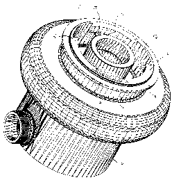
Figure 2 is a perspective view of the pump cylinder; and
Figure 3 is a perspective view of the engine cylinder.
Description of a preferred embodiment of the invention
Referring now to Figures 2 and 3, the pumping apparatus according to the
present invention comprises a prior art pump (shown in Fig. 1 ) and a prior
art
engine (also shown in Fig. 1 ). The invention lies in the connecting means for
connecting the pump and the engine together.

CA 02288462 1999-11-03
3
Fig. 2 shows the pump 10 and the pump cylinder 11. The pump cylinder is
preferably provided with an annular flange 13. The connecting means comprise a
plurality of lugs 15, interspaced by a plurality of spaces 17. The inside
surface 19
of each lug 15 forms a cam.
Fig. 3 shows the engine cylinder 21, also provided with an annular flange
23, having a size substantially similar to the flange 13 of the pump cylinder
11.
The connecting means comprise a plurality of lugs 25, having a shape a size
designed to fit inside the spaces 17. The inside surface of the lugs 25 mates
with
the inside surtace of the lugs 15.
In order to couple the engine and the pump, the lugs 25 are aligned with the
spaces 17 and the two cylinders are brought towards each other so that their
flanges 23, 13 faces each other and touch each other. One of the cylinders is
then
rotated by a predetermined amount, to provide engagement between the inside
surfaces of the lugs 25 and 15. Preferably, the direction of rotation of the
cylinders
is the same as the direction of rotation of the engine shaft driving the pump,
so
that a moment is created, forcing the cylinders to tighten even further.
Preferably, the inside surface of the lugs 15 is angled, to provide a
tightening of the two cylinders as they are rotated with respect to each
other.
Finally, since the engine, during operation, vibrates, this vibration could
have a tendency to loosen the connecting means. In order to prevent this
problem, shock absorbing means, preferably in the form of an O-ring made of
any
appropriate material, is preferably arranged on one of the flanges 23, 13, to
minimize the impact of the vibration.
Also preferably, locking means (not shown) are further provided for locking
the connecting means when engaged. These locking means could include two
holes on the flanges. When the connecting means are engaged, the two holes are
in alignment, and a pin is inserted therethrough to prevent rotational
movement
and inadvertent uncoupling of the connecting means during operation.
It should also be understood that the connection between the shaft of the
engine and the pump is as according to the prior art, or well within the skill
of a
person versed in this field.

CA 02288462 1999-11-03
4
Although the present invention has been explained hereinabove by way of a
preferred embodiment thereof, it should be pointed out that any modifications
to
this preferred embodiment within the scope of the appended claims is not
deemed
to alter or change the nature and scope of the present invention.

Representative Drawing
A single figure which represents the drawing illustrating the invention.
Administrative Status

2024-08-01:As part of the Next Generation Patents (NGP) transition, the Canadian Patents Database (CPD) now contains a more detailed Event History, which replicates the Event Log of our new back-office solution.

Please note that "Inactive:" events refers to events no longer in use in our new back-office solution.

For a clearer understanding of the status of the application/patent presented on this page, the site Disclaimer , as well as the definitions for Patent , Event History , Maintenance Fee  and Payment History  should be consulted.

Event History

Description Date
Inactive: IPC from MCD 2006-03-12
Application Not Reinstated by Deadline 2002-02-06
Inactive: Dead - No reply to Office letter 2002-02-06
Deemed Abandoned - Failure to Respond to Maintenance Fee Notice 2001-11-05
Application Published (Open to Public Inspection) 2001-05-03
Inactive: Cover page published 2001-05-02
Inactive: Status info is complete as of Log entry date 2001-03-19
Inactive: Abandoned - No reply to Office letter 2001-02-06
Inactive: First IPC assigned 1999-12-17
Inactive: Filing certificate - No RFE (English) 1999-12-03
Application Received - Regular National 1999-12-02

Abandonment History

Abandonment Date Reason Reinstatement Date
2001-11-05

Fee History

Fee Type Anniversary Year Due Date Paid Date
Application fee - standard 1999-11-03
Owners on Record

Note: Records showing the ownership history in alphabetical order.

Current Owners on Record
WILDFIRE FIRE EQUIPMENT INC.
Past Owners on Record
PATRICK RENAUD
Past Owners that do not appear in the "Owners on Record" listing will appear in other documentation within the application.
Documents

To view selected files, please enter reCAPTCHA code :


To view images, click a link in the Document Description column. To download the documents, select one or more checkboxes in the first column and then click the "Download Selected in PDF format (Zip Archive)" or the "Download Selected as Single PDF" button.

List of published and non-published patent-specific documents on the CPD .

If you have any difficulty accessing content, you can call the Client Service Centre at 1-866-997-1936 or send them an e-mail at CIPO Client Service Centre.


Document
Description 
Date
(yyyy-mm-dd) 
Number of pages   Size of Image (KB) 
Claims 2001-05-02 1 2
Abstract 2001-05-02 1 2
Drawings 1999-11-02 3 159
Description 1999-11-02 4 144
Representative drawing 2001-04-03 1 32
Filing Certificate (English) 1999-12-02 1 164
Request for evidence or missing transfer 2000-11-05 1 109
Courtesy - Abandonment Letter (Office letter) 2001-03-12 1 169
Reminder of maintenance fee due 2001-07-03 1 112
Courtesy - Abandonment Letter (Maintenance Fee) 2001-12-02 1 183
Correspondence 1999-12-02 1 14
Correspondence 2001-07-25 1 18