Note: Descriptions are shown in the official language in which they were submitted.
CA 02288555 1999-11-04
GAS TURBINE COMBUSTOR
BACKGROUND OF THE INVENTION:
Field of the Invention:
The present invention relates generally to a
combustor of gas turbine and more particularly to a combustor
structured such that uniformity of combustion air intake is
attained so as to enhance combustion efficiency and combustor
cooling ability as well as a fitting structure of structural
portions which are less endurable against thermal stress, such
as a combustor main swirler or a pilot cone, is improved so as
not to be influenced by high temperature, thereby overall
efficiency of the gas turbine combustor is enhanced in the
recent tendency of higher temperature of combustion gas. The
present invention also relates to a combustor of gas turbine
having a reduced combustion vibration.
Description of the Prior Art:
Fig. 20 is a structural arrangement view of a
representative gas turbine combustor and surrounding portions
thereof in the prior art. In Fig. 20, numeral 20 designates
a combustor, which is provided in a turbine cylinder 50.
Numeral 21 designates a main fuel nozzle, which is provided in
plural pieces in a combustor circumferential direction to be
supplied with a main fuel of oil or gas. Numeral 22 designates
a pilot fuel nozzle, which is provided in a central portion of
- 1 -
CA 02288555 1999-11-04
the plural main fuel nozzles 21 for igniting the main fuel
nozzles 21. Numeral 23 designates a combustion chamber, and
numeral 24 designates a tail tube, from which a high temperature
gas produced in the combustion chamber 23 is led into a gas
turbine. Numeral 62 designates a compressor, numeral 63
designates an air outlet, numeral 64 designates an air
separator for supplying gas turbine blades with outside air for
cooling thereof, numeral 65 designates a gas turbine stationary
blade and numeral 66 designates a gas turbine moving blade.
In the combustor constructed as mentioned above, air
40 coming from the compressor 62 flows into the turbine cylinder
50 via the air inlet 63 and further flows into the combustor
for effecting a combustion from around the combustor 20
through spaces formed between stays, described later, as air
15 shown by numerals 40a, 40b. In the flow of the air 40 at this
time, there arise differences in the flow rate and pressure
between the air 40a which is near the air outlet 63 or the
compressor 62 and the air 40b which is far from the air outlet
63 or the compressor 63 and this causes a non-uniformity in the
20 air flow entering the combustor 20 according to the
circumferential directional position thereof with result that
a biased flow of air arises in an inner tube, described later,
in the combustor 20 to cause a non-uniformity of fuel flow as
well, which leads to an increase of NOX formation.
Fig. 21 is an enlarged structural arrangement view
- 2 -
CA 02288555 1999-11-04
of the gas turbine combustor of Fig. 20. In Fig. 20, there are
shown several structural portions having shortcomings to be
solved. That is, (X-1) portion and (X-2) portion, respectively,
are air intake portions into the fuel nozzles, (X-3) portion
is a main swirler fitting structural portion, (X-4) portion is
a pilot cone fitting structural portion and (X-5) portion is
a tail tube cooling structural portion and there are problems
to be solved in the respective portions. Such problems as
existing in the present situation will be described below
sequentially.
The air intake portion ( X-1 ) will be described f first .
Fig. 22 is a cross sectional view of a top hat type fuel nozzle
portion of a prior art gas turbine. In Fig. 22, the air 40a,
40b coming from the compressor flows into the combustor 20 for
effecting a combustion from around the combustor 20 through
spaces formed between stays 25 provided in the combustor 20.
Between the air 40a which is near the compressor and the air
40b which is far from the compressor, there are differences in
the flow passages themselves and shapes thereof, which causes
a non-uniformity in the flow rate of the air flowing into the
combustion chamber 23 according to the circumferential
directional position thereof to cause a biased flow of the air.
By this biased flow of the air, fuel flow also becomes non-
uniform in the combustion chamber and NOx formation increases
there. It is needed, therefore, that the air flow into the
- 3 -
CA 02288555 1999-11-04
combustor is uniform in the circumferential direction.
Also, in the combustor of Fig. 22 which is of the top
hat type, there is fitted to the turbine cylinder 50 an outer
tube casing cover 51 for covering a portion where the fuel
nozzles are inserted. On the other hand in the combustor of
Fig. 20, the air intake portion is arranged in a space formed
by a cylindrical casing of the turbine cylinder 50. In the
example of Fig. 22, a portion surrounding the stays 25 as the
air intake portion is covered by the cylindrical outer tube
casing cover 51 and the outer tube casing cover 51 is of a
hat-like shape which projects toward outside. In this type of
combustor, a central axis 61 of the outer tube casing cover 51
of the turbine cylinder 50 and a central axis 60 of the combustor
do not coincide with each other and the combustor is fitted to
the outer tube casing cover 51 so as to incline slightly thereto.
Although detailed explanation on the reason therefor is omitted,
while the combustion gas flowing through the inner tube and the
tail tube is led into a gas turbine combustion gas path, it is
needed to make temperature distribution of the gas flow uniform
as much as possible and in order to realize an optimized
temperature distribution according to the fitting manner of the
combustor, the central axis 60 of the combustor is inclined
slightly relative to that 61 of the outer tube casing cover 51.
In the portion surrounding the stays 25 as the air
intake portion in such combustor, there are differences along
- 4 -
CA 02288555 1999-11-04
the circumferential direction in the space areas formed by the
outer tube casing cover 51 and the stays 25 and while a quantity
of intake air is so adjusted, there is still a non-uniformity
of the intake air there. In this type of the combustor, while
the outer tube casing cover 51 functions as a rectifier tube
to some extent so that there is obtained some rectifying effect
of the air flow coming into the combustor, as compared with the
combustor of Fig. 20, the air taken turns at the air intake
portion surrounding the stays 25 to flow into the nozzle portion,
which causes a non-uniformity of the air flow, hence an
improvement to realize a further uniform flow of the air is
desired.
Next, a problem existing in the air intake portion
(X-2) will be described. Fig. 23 is a side view of an inner
tube portion of the combustor 20 of Fig. 20. In Fig. 23, a high
temperature combustion gas 161 flows through inside of an inner
tube 28. In a circumferential surface of the inner tube 28 which
is exposed to the high temperature gas, there are provided a
multiplicity of small cooling holes ( not shown ) and air flowing
through these cooling holes cools the inner tube 28 to then flow
out to be mixed into the combustion gas flowing inside the inner
tube 28. On the other hand, there remains an unburnt component
of fuel in the combustion gas flowing through the inner tube
28 to increase NOx formation, hence it is necessary to burn the
unburnt component sufficiently. For this purpose, there are
- 5 -
CA 02288555 1999-11-04
provided in the circumferential surface of the inner tube 28
air holes 10-1, 10-2, 10-3 formed in three rows with six pieces
of air holes in each of the rows, said six pieces of air holes
of each row being arranged with equal intervals between them
in the circumferential direction of the inner tube 28, as shown
in Fig. 23.
In the inner tube 28 constructed as above, the
combustion gas 161 produced by the main fuel nozzle 21 flows
through the inner tube 28 to flow to the tail tube 24, and for
combustion of the unburnt component of fuel contained in the
high temperature combustion gas 161, air 130 is led into the
inner tube 28 through the first row air holes 10-1 and the second
row air holes 10-2. Further, air 131 is led into the inner tube
28 through the third row air holes 10-3 of downstream for
combustion of the unburnt component still remaining unburnt.
The air entering the combustor 20 comprises three
portions, that is, the air used for combustion at the nozzle
portion of the combustor, the air entering the inner tube 28
for cooling thereof through the small cooling holes and the air
2 0 13 0 , 131 f lowing into the inner tube 2 8 through the air holes
10-1, 10-2, 10-3. Where the total quantity of these three
portions of the air is 100%, as one example in a prior art
combustor, the quantity of the air flowing through the air holes
10-1, 10-2 is about 14~, respectively, and that of the air
flowing through the air holes 10-3 is about 19 to 20% . If the
- 6 -
CA 02288555 1999-11-04
respective quantities are expressed in ratio for the air holes
10-1, 10-2 and 10-3, it is expressed approximately as 1:1: ( 1.3
to 1.4 ) . That is, the air quantity entering the inner tube 28
through the air holes 10-3 of downstream is largest. But if
the air quantity entering through the air holes 10-3 becomes
excessive, it remains unused for the combustion but cools
flames of the high temperature combustion gas to thereby cause
a colored smoke.
Next, a problem existing in the main swirler portion
(X-3) will be described. In a prior art multiple type
premixture combustor of gas turbine, a pilot swirler is
provided in a center thereof and eight pieces of main swirlers
are arranged therearound and each of the main swirlers is fixed
by welding to an inner wall of the combustor via a thin fixing
member of about 1.6 mm thickness. Fig. 24 is a cross sectional
side view showing a swirler portion and a pilot cone portion
of said type of combustor in the prior art and Fig. 25 is a
partial view seen from plane H-H of Fig. 24. In Figs. 24 and
25, numeral 20 designates a combustor, numeral 31 designates
a pilot swirler provided in a center of the combustor 20 and
numeral 33 designates a pilot cone fitted to an end of the pilot
swirler 31. Numeral 32 designates a main swirler, which is
arranged in eight pieces around the pilot swirler 31. Numeral
34 designates a base plate, which is formed in a circular shape
and has its circumferential portion fixed by welding to the
_ 7 _
CA 02288555 1999-11-04
inner wall of the combustor 20. In the base plate 34, there
is provided a hole in a center portion thereof which the pilot
swirler 31 passes through, being inserted, to be supported and
also provided are eight holes around the hole of the center
which the main swirlers 32 pass through, being inserted, to be
supported.
Numeral 35 designates a fixing metal member, which
is made by a metal plate and is interposed to fix each of the
eight main swirlers 32 to the inner circumferential wall of an
end portion 36 of the combustor 20 by welding, as shown in Fig.
25, wherein the main swirlers 32 are seen being fixed to the
inner circumferential wall of the end portion 36 of the
combustor 20 via the fixing metal member 35. Although omitted
in the illustration, a main fuel nozzle has its front end
portion inserted into the main swirler 32 and a pilot fuel
nozzle has its front end portion inserted into the pilot swirler
31, and main fuel injected from the main fuel nozzle mixes with
air coming from the main swirler 32 to be ignited for combustion
by flame, said flame being made by pilot fuel coming from the
pilot fuel nozzle together with air coming from the pilot cone
33 of the pilot swirler 31. The mentioned combustor 20 is
arranged in several tens pieces, 16 pieces for example,
circularly around a rotor in a gas turbine cylinder for
supplying therefrom a high temperature combustion gas into a
gas turbine combustion gas path for rotation of the rotor.
_ g _
CA 02288555 1999-11-04
In the gas turbine combustor so made in the welded
structure, there occurs a deformation due to vibration or
thermal stress in operation to cause cracks in the welded
portion of the fixing metal member 35, which requires repairing
work frequently to replace the fixing metal member 35 or carry
out additional welding work. In the fitting portion of the
fixing metal member 35, there is only a narrow space for welding
work to be in a bad condition for performing a satisfactory
welding, so that a high level of skill of workers is required.
Also, in making the welded structure, a fine adjustment for
fitting is difficult, which restricts the accuracy to be
maintained, that is, there is a problem in work accuracy in
making the welded structure.
Next, a problem existing in the pilot cone portion
(X-4) will be described. In the combustor 20 described with
respect to Figs. 24 and 25, the main fuel nozzle is inserted
into the central portion of the main swirler 32, and main fuel
injected from the main fuel nozzle and air coming from the main
swirler 32 are mixed together to form a premixture. On the other
hand, the pilot fuel nozzle is inserted into the central portion
of the pilot swirler 31, and pilot fuel injected from the pilot
fuel nozzle together with air coming from the pilot swirler 31
burns to ignite the premixture of the main fuel for combustion
in a combustion tube, which includes an inner tube and a
connecting tube, to thereby produce the high temperature
_ g _
CA 02288555 1999-11-04
combustion gas.
Fig. 26 is a partial detailed cross sectional view
of a fitting portion of the pilot cone 33 of Fig. 24. In Fig.
26, a cone ring 38 at its one end is fitted to an outer wall
of the pilot cone 33 by welding W2. The cone ring 38 at the
other end is fitted to a fitting member 39b, which is an integral
part of a base plate 39, by welding W1. The pilot cone 33 is
inserted into a cylindrical portion 39a of the base plate 39
to be fixed to the base plate 39 by welding W3. An end portion
31a of the pilot swirler 31 is inserted into the pilot cone 33
to be fitted to the pilot cone 33 by welding W4. In the welding
W4, a black arrow in Fig. 26 shows a direction in which the
welding is carried out. Thus, the pilot cone 33 is fitted to
the base plate 39 via the cone ring 38 by welding W3 and the
pilot swirler 31 is fitted to the pilot cone 33 by welding W4.
Hence, the base plate 39 fixes the central pilot swirler 31,
the pilot cone 33 and the eight pieces of the main swirlers 32
by welding, as mentioned above, to support them in a base plate
block.
In the mentioned welded fitting structure, as fitting
work procedures thereof, the cone ring 38 is first fitted to
around the fitting member 39b of the base plate 39 by welding
1 and then the pilot cone 33 is fitted to the cone ring 38 by
welding W2. The pilot cone 33 is then fitted to the base plate
39 by welding W3 which is done around an end portion of the pilot
- 10 -
CA 02288555 1999-11-04
cone 33. Thereafter, the pilot swirler 31 is inserted into the
end portion of the pilot cone 33 to be fitted to the pilot cone
33 by welding W4 to be done therearound. Thus, in case the pilot
cone 33 is to be uncoupled in said welded structure, the welding
W2, W3 and W4 needs to be detached, but in the spaces around
the welding W2, W3, there are arranged the main swirlers 32 to
make the work space very narrow, which results in the need to
disassemble the entire part of the base plate block. In this
situation, the accuracy of the welding is deteriorated to be
influenced easily by the thermal stress of the high temperature
gas.
As the pilot swirler 31 and the pilot cone 33 are
continuously influenced by the high temperature combustion gas
and the base plate block is made in the thin plate structure,
as mentioned above, there arise cracks easily due to strain by
the thermal stress, which needs repairing work frequently with
a high level of welding skill and an improvement of such welded
structure is desired.
Next, a problem existing in the tail tube cooling
portion (X-5) will be described. In the recent higher
temperature tendency of the gas turbine, a combustor is being
developed in which the combustion gas becomes a high
temperature of about 1500°C and a cooling system thereof is
being tried to be changed to a steam cooling type from an air
cooling type. Fig. 27 is an explanatory view showing a tail
- 11 -
CA 02288555 1999-11-04
tube cooling structure in a representative gas turbine
combustor in the prior art, which has been developed by the
applicants here, wherein Fig. 27(a) is an entire view, Fig.
27(b) is a perspective view showing a portion of a tail tube
wall and Fig. 27 (c ) is a cross sectional view taken on line J-J
of Fig . 2 7 ( b ) . In Fig . 2 7 ( a ) , numeral 2 0 des ignates a combustor,
which comprises a combustion tube and a tail tube 24. Numeral
22 designates a pilot fuel nozzle, which is arranged in a
central portion of the combustion tube and numeral 21
designates a main fuel nozzle, which is provided in eight pieces
thereof around the pilot fuel nozzle 22. Numeral 26 designates
a main fuel supply port, which supplies the main fuel nozzles
21 with fuel 141. Numeral 27 designates a pilot fuel supply
port, which supplies the pilot fuel nozzle 22 with pilot fuel
140.
Numeral 125 designates a cooling steam supply pipe
for supplying therethrough steam 133 for cooling. Numeral 126
designates a cooling steam recovery pipe for recovering
therethrough recovery steam 134 after used for cooling of the
tail tube 24 of the combustor. Numeral 127 designates a cooling
steam supply pipe, which supplies therethrough cooling steam
132 from a tail tube outlet portion for cooling of the tail tube
24, as described later.
In Fig. 27 (b) showing a portion of a wall 20a of the
tail tube 24, there are provided a multiplicity of steam
- 12 -
CA 02288555 1999-11-04
passages 150 in the wall 20a and steam passing therethrough
cools the wall 20a. In Fig. 27(c), a steam supply hole 150a
and a steam recovery hole 150b are provided respectively to
communicate with the steam passages 150 so that steam supplied
through the steam supply hole 150a flows through the steam
passages 150 for cooling of the wall 20a and is then recovered
through the steam recovery hole 150b.
In the combustor so constructed, the main fuel 141
is supplied into the eight pieces of the main fuel nozzles 21
from the main fuel supply port 26. On the other hand, the pilot
fuel 140 is supplied into the pilot fuel nozzle 22 from the pilot
fuel supply port 27 to be burned for ignition of the main fuel
injected from the surrounding main fuel nozzles 21. Combustion
gas of high temperature thus produced flows through the
combustion tube and the tail tube 24 to be supplied into a
combustion gas path of a gas turbine (not shown) and while
flowing between stationary blades and moving blades, it works
to rotate a rotor. The combustor so constructed is arranged
in various plural pieces according to the model or type, for
example 16 pieces, around the rotor and the high temperature
gas of about 1500°C flows in the outlet of the tail tube 24 each
of the combustors. Thus, the combustor 20 needs to be cooled
by air or steam.
In the combustor of Fig. 27, a steam cooling system
is employed and the cooling steam 132, 133, extracted from a
- 13 -
CA 02288555 1999-11-04
steam source ( not shown ) , is supplied through the cooling steam
supply pipe 127, 125, respectively, to flow through the
multiplicity of steam passages 150 provided in the wall 20a of
the tail tube 24 for cooling of the wall 20a and then join
together in the cooling steam recovery pipe 126 to be recovered
as the recovery steam 134 and to be returned to the steam source
for an effective use thereof.
Fig. 28 is a view seen from plane K-K of Fig. 27(a)
to show an outlet portion of the tail tube 24. Numeral 160
designates a combustion gas path, through which the high
temperature combustion gas of about 1500°C is discharged.
A flange 71 for connection to the gas turbine combustion gas
path is provided at an end periphery of the outlet portion of
the tail tube 24. Fig. 29 is a cross sectional view taken on
line L-L of Fig. 28 to show a steam cooled structure of the tail
tube outlet portion in the prior art. In Fig. 29, the
multiplicity of steam passages 150 are provided in the wall 20a,
as mentioned above, in parallel with each other. A cavity 75
is formed in an entire inner circumferential peripheral portion
of the flange 71 of the tail tube 24 outlet portion and the
multiplicity of steam passages 150 communicate with the cavity
75.
A manifold 73 is formed being covered circum-
ferentially by a covering member 72 between an outer surface
portion of the wall 20a of the tail tube 24 and the flange 71
- 14 -
CA 02288555 1999-11-04
and the respective steam passages 150 communicate with the
manifold 73 via respective steam supply holes 74.
In the mentioned steam cooled structure, a high
temperature combustion gas 161 of about 1500°C on one hand flows
in the combustion gas path 160 and on the other hand, the
temperature of air flowing outside of the manifold 73 within
the turbine cylinder is about 400 to 500°C. While an inner
peripheral surface portion of the wall 20a and that of the tail
tube 24 outlet portion which are exposed to the high temperature
combustion gas 161 are cooled sufficiently by the cooling steam
132 flowing into the steam passages 150 from the manifold 73
via the steam supply holes 74, the steam in the cavity 75 cools
also a portion 20b which is not exposed to the high temperature
combustion gas 161 and further the cooling steam 132 in the
manifold 73 cools a portion 20c as well. Hence, as compared
with the inner wall 20a, the portions 20b, 20c are cooled
excessively to cause a differential thermal stress between the
wall 20a and the portions 20b, 20c to thereby cause unreasonable
forces therearound, which results in the possibility of crack
occurrence, etc.
The gas turbine combustor in the prior art as
described above is what is called a two stage combustion type
gas turbine combustor effecting a pilot combustion and a main
combustion at the same time, said pilot combustion being done
such that fuel is supplied along the central axis of the
- 15 -
CA 02288555 1999-11-04
combustor and combustion air for burning this fuel is supplied
from therearound to form a diffusion flame (hereinafter
referred to as a pilot flame) in the central portion of the
combustor and said main combustion being done such that a main
fuel premixture having a very high excess air ratio is supplied
around the pilot flame so as to make contact with a high
temperature gas of the pilot flame to thereby form a premixture
flame (hereinafter referred to as a main flame). Fig. 30 is
a conceptual view of such a two stage combustion type gas
turbine combustor in the prior art.
If a further detail is described with reference to
Fig. 30, within a liner 252 of the combustor 20, the pilot fuel
nozzle 22 for injecting a pilot fuel is provided along a central
axis O' and a pilot air supply passage 256 is provided around
the pilot fuel nozzle 22. The pilot swirler 31 for flame holding
is provided in the pilot air supply passage 256. Further, the
main fuel nozzles 21, main air supply passages 258 and the main
swirlers 32 for supplying main fuel are provided around the
pilot air supply passage 256.
The pilot cone 33 is provided downstream of the pilot
fuel nozzle 22 and the pilot air supply passage 256. The fuel
supplied from the pilot fuel nozzle 22 and the air supplied from
the pilot air supply passage 256 effect a combustion in a pilot
combustion chamber 262 formed by the pilot cone 33 to form the
pilot flame as shown by arrow 266. The fuel supplied from the
- 16 -
CA 02288555 1999-11-04
main fuel nozzles 21 and the air supplied from the main air
supply passages 258 are mixed together in a mixing chamber 264
downstream thereof to form the premixture as shown by arrow 268.
This premixture 268 comes in contact with the pilot flame 262
to form the main flame 270.
In the prior art combustor 20, as the pilot flame 266
and the premixture 268 come in contact with each other in a
comparatively short time, the premixture 268 is ignited easily,
thereby the main flame 270 burns in a comparatively short length
in the axial direction or the main flow direction to be liable
to form a short flame. If the combustion is done in such a short
length, or in other words, in a narrow space, a concentration
of energy released by the combustion in the space or a cross
sectional combustion load of the combustor becomes high to
cause combustion vibration easily. Combustion vibration is a
self-induced vibration caused by a portion of the thermal
energy being converted to vibration energy and as the cross
sectional combustion load of the combustor becomes higher,
exciting force of the combustion vibration becomes larger and
the combustion vibration becomes more liable to occur. As
mentioned above, in the prior art combustor, the combustion
load is high comparatively and there is a problem that the
combustion becomes unstable due to the combustion vibration.
SUMMARY OF THE INVENTION:
- 17 -
CA 02288555 1999-11-04
In the prior art gas turbine combustor as described
above mainly with reference to Fig. 20, non-uniformity of the
air intake in the air intake portions of (X-1) and (X-2),
influence of the thermal stress due to the work process and work
accuracy of the welded structures of the fitting portions of
the main swirlers of (X-3) and of the pilot cone of (X-4),
influence of the thermal stress due to non-uniformity of
cooling of the tail tube cooling portion of (X-5), etc. are
obstacles in attaining the higher temperature and higher
efficiency of the gas turbine combustor and for realization
thereof, further improvements of the mentioned portions of
(X-1) to (X-5) are desired strongly.
Thus, it is an object of the present invention to
provide a gas turbine combustor which makes uniform the air
intake in the air intake portions of (X-1) and (X-2) and
realizes an optimal combustion air quantity therein, employs
a fitting structure to mitigate the influence of the thermal
stress in the thermally severest portions of the main swirler
portion of (X-3 ) and of the pilot cone portion of (X-4 ) and also
employs a cooling structure to ensure a cooling uniformity of
the tail tube cooling portion of ( X-5 ) to thereby totally solve
the obstacles accompanying with the higher temperature of the
combustor to realize a higher performance thereof.
Also, it is an object of the present invention to
provide a gas turbine combustor having a reduced combustion
- 18 -
CA 02288555 1999-11-04
vibration.
In order to attain said object, the present invention
provides the following means of (1) to (9).
(1) A gas turbine combustor constructed such that
an inner tube, a connecting tube and a tail tube are arranged
to be connected sequentially from a fuel inlet side, said inner
tube comprises a pilot swirler arranged in a central portion
of said inner tube and a plurality of main swirlers arranged
around said pilot swirler, said pilot swirler and each of said
main swirlers at their respective end portions pass through a
circular base plate to be supported, said circular base plate
is supported being fixed to an inner circumferential surface
of said inner tube and an outlet portion of said tail tube is
connected to a gas turbine inlet portion, characterized in that
said inner tube comprises an air intake means for making air
intake into the combustor uniform, said pilot swirler or each
of said main swirlers comprises a holding means for mitigating
thermal stress and said outlet portion of the tail tube
comprises a cooling means for attaining a uniform cooling.
In the present invention of (1) above, which is a
basic one of the invention here, the air intake means makes the
air flowing into the combustor uniform and air quantity flowing
into the inner tube through air holes provided in the
circumferential wall of the inner tube is adjusted to an
appropriate quantity, thereby a good combustion is attained
- 19 -
CA 02288555 1999-11-04
with less formation of NOX and a colored smoke generated by the
combustion can be suppressed as well. Also, by the holding
means, the structural portions, such as the pilot swirler and
the main swirlers, which are liable to receive influence of
thermal stress are made such that the thermal stress is absorbed,
repair and inspection become easy and welding of high accuracy
become possible, thereby shortcomings of weld cracks, etc. can
be suppressed. Further, by the cooling means of the tail tube,
in case a steam cooling is employed, non-uniformity of the
cooling of the tail tube outlet portion is avoided and by the
uniform cooling at this portion, cracks due to thermal stress,
etc . can be prevented . Thus , according to the present invention
of (1) above, the combustion uniformity in the higher
temperature of gas turbine and the structural portions of
severe thermal stress are improved as well as the cooling
structure to attain the uniform cooling to prevent generation
of thermal stress at the tail tube outlet portion is employed,
with result that the performance enhancement of the gas turbine
combustor in the higher temperature tendency of the combustion
gas becomes possible.
( 2 ) A gas turbine combustor as mentioned in ( 1 ) above,
characterized in that said air intake means is constructed such
that a rectifier tube is provided to cover surroundings of said
inner tube on said fuel inlet side, keeping a predetermined
space from said inner tube and said rectifier tube at one end
- 20 -
CA 02288555 1999-11-04
is fixed to a turbine cylinder wall and at the other end opens.
In the present invention of (2) above, the air
supplied from the compressor flows in around the combustor from
said the other end of the rectifier tube and while it flows
through the predetermined space between the rectifier tube and
the combustor inner tube, it is rectified to be a uniform flow
with an appropriate quantity and flows into the combustion
chamber through the gaps formed by the plural stays . The air
so flowing around is of a uniform flow without biased flow so
that fuel concentration at the nozzle outlet becomes uniform,
thereby a good combustion is attained and increase of NOX
formation can be suppressed. The mentioned rectifier tube may
be applied to either of a combustor of a type having a wider
space of combustor air inflow portion in the turbine cylinder
or what is called a top hat type combustor having the air inflow
portion being covered by a casing, with the same effect being
obtained in both cases thereof.
( 3 ) A gas turbine combustor as mentioned in ( 2 ) above,
characterized in that said rectifier tube at one end comprises
a sloping portion in which a diameter thereof contracts
gradually.
In the present invention of ( 3 ) above, the rectifier
tube at its one end comprises the sloping portion in which the
diameter of the rectifier tube contracts gradually, thereby the
air flowing therein strikes the inner circumferential surface
- 21 -
CA 02288555 1999-11-04
of the sloping portion and changes the direction of flow
entering the combustion chamber smoothly so that the air flows
uniformly toward the central portion of the combustor with
increased rectifying effect, hence the effect of the invention
of (2) above is ensured further.
( 4 ) A gas turbine combustor as mentioned in ( 1 ) above,
characterized in that said air intake means is constructed such
that a plurality of air holes are provided in a circumferential
wall of said inner tube, being arranged in a plurality of rows
in a flow direction of combustion gas flowing from upstream to
downstream in said inner tube and, where air supplied from a
fuel nozzle portion for combustion of fuel, air supplied for
cooling of the combustor and air supplied into said inner tube
through said plurality of air holes are a total quantity of air,
air supplied into said inner tube through said air holes of a
most downstream row of said plurality of rows is 7 to 12~
thereof.
In the gas turbine combustor, there are three
portions of air flow thereinto, that is, air used for combustion
of fuel supplied from the main fuel nozzles and the pilot fuel
nozzle, air flowing into the inner tube through cooling holes
provided in the inner tube wall for cooling of the inner tube
and air flowing into the inner tube through air holes for
burning unburnt component of fuel. Said air holes are provided
in the circumferential wall of the inner tube in plural pieces
- 22 -
CA 02288555 1999-11-04
arranged in plural rows, three rows for example, in the gas flow
direction in the inner tube. In the prior art, air quantity
flowing in the two rows of upstream side, respectively, is same
to each other and that flowing in the row of the most downstream
side is more than that, for example about 20~ of the entire air
quantity of said three portions, and if the air flowing into
the inner tube through the air holes of the most downstream row
becomes excessive at a low load time, the combustion gas is
cooled to increase colored smoke. In the present invention of
( 4 ) above, however, the air quantity entering through the air
holes of the most downstream row is suppressed to 7 to 12~ of
the entire air quantity, which is approximately a half of the
prior art case, hence generation of the colored smoke can be
suppressed.
( 5 ) A gas turbine combustor as mentioned in any one
of ( 1 ) to ( 4 ) above, characterized in that said holding means
is constructed such that each of said plurality of main swirlers
at an inlet portion thereof is fixed to an inner circumferential
surface of said inner tube via a fitting member and the fixing
of each of said main swirlers and said fitting member to said
inner tube is done by a bolt joint.
In the present invention of (5) above, the main
swirler at its outlet end portion as well as the pilot swirler
are supported by the base plate and the base plate is fitted
to the inner circumferential surface of the combustor. Also,
- 23 -
CA 02288555 1999-11-04
the main swirler at its inlet end portion is jointed to the inner
circumferential surface of the combustor by the bolt via the
fitting member, thereby the fitting work becomes easy, fine
adjustment for the fitting can be done easily and accuracy of
the fitting position is enhanced.
The holding structure is a welded structure in the
prior art, so that cracks occur easily in the welded portions
of the fitting member of the main swirler due to thermal stress,
etc . in operation, there is a limitation in the accuracy of the
product made in the welded structure of thin metal plates and
deformation occurs due to residual strain in the welded
portions in addition to the thermal stress to cause mutual
contact of the main swirler and the main fuel nozzles to
increase abrasion. Further, there is only a narrow space for
welding work of the fitting member to deteriorate the
workability. But in the present invention of (5) above, said
shortcomings are improved to enhance reliability of the product
and manufacturing cost thereof is reduced as well.
( 6 ) A gas turbine combustor as mentioned in any one
of ( 1 ) to ( 4 ) above, characterized in that said holding means
is constructed such that an outer diameter of an inlet end
portion of a pilot cone which is arranged on an outlet side of
said pilot swirler is made approximately equal to an outer
diameter of an outlet end portion of said pilot swirler so that
said inlet end portion of the pilot cone abuts on said outlet
- 24 -
CA 02288555 1999-11-04
end portion of the pilot swirler and welding is applied there
from inside of said pilot cone to joint said pilot swirler and
said pilot cone together.
In the present invention of (6) above, the pilot
swirler passes through the central cylindrical portion of the
base plate to be supported and the inlet portion end of the pilot
cone abutting thereon is jointed by welding which is done from
inside of the pilot cone. Thereby, in case the pilot cone is
damaged by burning in operation to require replacement thereof,
the welded portion of the pilot cone is removed from inside
thereof and the welded portion of the pilot cone and the fitting
member of the base plate is also removed, so that the pilot cone
only can be taken out easily and the replacement work thereof
is done easily. In the prior art, if the pilot cone is to be
detached, it is needed to disassemble the entire swirler in each
of the base plate blocks. But the welded structure of the
present invention is made such that the pilot swirler is first
fitted to the base plate and then the pilot cone is welded to
the pilot swirler and the welding is done from inside of the
pilot cone, so that detachment of the pilot cone can be done
easily, replacement thereof becomes easy and workability
thereof is improved. According to such welded structure as
having the high workability, accuracy of the welding is
enhanced and reliability in attaining the higher temperature
of the gas turbine is also enhanced.
- 25 -
CA 02288555 1999-11-04
( ? ) A gas turbine combustor as mentioned in any one
of ( 1 ) to ( 4 ) above, characterized in that said cooling means
is constructed such that a steam manifold is formed being closed
by a covering member to cover an outer circumference of an
outlet portion of said tail tube and an end flange of said outlet
portion of the tail tube, a plurality of steam passages are
provided in a wall of said tail tube extending from said
connecting tube to near said end flange of the tail tube, said
plurality of steam passages communicate with said steam
manifold and a cavity formed in an entire inner circumferential
portion of said outlet portion of the tail tube near said end
flange and said steam manifold is partitioned therein by a rib
to form two hollows, one on the side of said end flange for
covering at least an outer side of said cavity and the other
for steam flow therein.
In the present invention of ( 7 ) above, the hollow is
provided to cover the outer circumferential surface of the tail
tube outlet portion near the end flange and this hollow covers
also the outer side of the cavity. Thus, the outer side of the
cavity makes contact with the air layer in the hollow so as not
to be cooled directly by the steam in the steam manifold. In
the prior art, the outer side of the cavity is cooled directly
by the steam in the cavity and that in the steam manifold to
be cooled excessively, which causes differential temperature
between the inner circumferential surface of the tail tube
- 26 -
CA 02288555 1999-11-04
outlet portion and the outer side structural components thereof
to cause thermal stress there. But in the present invention,
such excessive cooling is avoided to mitigate the differential
temperature between the tail tube outlet portion and the outer
side components and the thermal stress caused thereby can be
also mitigated.
( 8 ) A gas turbine combustor as mentioned in any one
of (1) to (7) above, characterized in that shield gas is
supplied between pilot air and main combustion premixture, said
pilot air being supplied from said pilot swirler and said main
combustion premixture being formed by main air supplied from
said main swirlers and main fuel being mixed together.
In the present invention of ( 8 ) above, the pilot fuel
is burned by the pilot air, thereby the pilot flame which
comprises the diffusion flame is formed. Like in the prior art
case, the main combustion premixture makes contact with the
pilot flame to burn as the premixture combustion. The shield
gas supplied around the pilot air suppresses the mutual contact
of the premixture and the pilot flame, thereby the combustion
velocity of the premixture is reduced, the main flame as the
premixture flame formed between the premixture and the pilot
flame becomes longer in the longitudinal direction of the
combustor and the combustion energy concentration is lowered.
( 9 ) A gas turbine combustor as mentioned in ( 8 ) above,
characterized in that said shield gas is a recirculated gas of
- 27 -
CA 02288555 2003-06-09
exhaust: gas proc~irced by °,~,r~~~;a:~st~o.r in said gas turbine
combos t:or .
In the ~.~rescr~t i.r~verr~ ion c~f ~ 9 i above, the shield
gas is supplied from; t::hc::~ rc:~:,ircvr:al.~-~ts~~~i gas c>f: thE~ gas
turbine exhaust gas, t_he r~:~xa~r~ t1n<~ r>.~yc~en concentxwrti.on in
the p remixture f Lame i s : ~~i:~~z .E.-~{:~ arad NO,~ forma~.ion is
suppressed.
Accordingly, iv ~.>r:,c~ mpE.~<.~n: ttm.:A invention resides
in a gas turbine cornbustc:~r cc.>nst:rw .tec.:l within a turbine
casing wall, comp3_isirug an u.rzrxfrr i;oi;~_r raving a fme1 inlet
side, a central portion ,~n,:a an :inner circumf~~rent.ial
surface; a c:onnec~t. incl t ~.~bf= ,~rui t3 t a i_1 tube sequf~nt:ially
connected to said inner t~z'~w~: such t:.ha;. ::~aict i.nnE,r tube,
said connecting tubes ancL ~:ic:3 a:i_7.t:uJ"re .ire sequc>nt:ially
arranged frGm sa_ d f.rza l r; ~~~: s i c~e ~:,1 s~,i_d i.nne~r tube,
wherein said tail tube has ~.trl c:ut.lc>t port:i.c>rr c.;onnect:ed to a
gas turbine inlc='t: ~~or ~::i~:oru; <~rud .r ~oc,:Ling mean; for
attaining unifor-m cc>c L irrg i ~:u :>ai.d c~i~tl.~.~t portion of said
tail tube; wl~ere:i.n >aic:~ inrxr=:r t ~::~c- comp.rise~s ~ pilot
%0 swirler arranged in said :c~.rt ral f~c>rt i.~:;~rr of said inner
tube, a pluraJit~~ of main .>>wi..r l.c=r.s ~mranged around said
pilot swirler, a ~:~irc:ular l:~as-x ~>:iota::a fixEr~~1 t::o said inner
circumferent:ia.l ;>;arfave of ~-,ai_ci inn:m: tube, wherein said
pilot swirler a~iud c ~~~:h ~~f sai.,l ma~ira swirlers have
f 5 respect:ive errd po :: t:io~ r .; i,a~>:.~ i n~_" ~::fut ;:~.~c~h ;a id
circF.z _ar base
plate so as to L:~ca sup~>c>rte~Y tfw ret:y, a plurality otv spaced
supports suppor_trirug said i_raruer tube ,gin ~ai.d turbine casing
wall and forming urn a~ c' int .:a'~e, .r rcv; titi~>r- tube fof~: making
air taken i_n '~c; ~a:i.d irGrmer rot>f~ ° 1 rc»,a 3t ~,a~.d ~i.~
intake
30 uni:Form, ;paid r:ec:t.i.fier: t:ui;.E~ c~rnpr:i.. ~:ing ~ sloping end
fixed
to said turbine c~as.in~~ ~,a<al.i., sa:l..:i ~.7.>p:Lrrc; end comp:c_i~~ing a
sloping portion hiavirug a a.c.~rzt.z:a=pct _-v~ ii arrieter, and said
_.
CA 02288555 2004-10-27
sloping portion extending around said supports, and said
rectifier tube further comprising an other end forming an
opening such that the other end maintains a predetermined
spacing from said inner tube, and a holding means for
holding at least one of said pilot swirler and said main
swirlers so as to mitigate thermal stress.
In another aspect the invention resides in a gas
turbine combustor arrangement of a gas turbine, comprising a
turbine casing having a turbine casing wall; an inner tube
having a field inlet side, wherein said inner tube is
connected at a downstream side thereof to a tail tube, and
wherein said tail tube has an outlet portion connected to a
gas turbine inlet portion; wherein said inner tube comprises
a pilot swirler arranged in a central portion of said inner
tube, a plurality of main swirlers arranged around said
pilot swirler, a plurality of spaced supports supporting
said inner tube on said turbine casing wall and forming an
air intake, and a rectifier tube for making air taken in to
said inner tube through said air intake uniform, said
rectifier tube comprising a sloping end fixed to said
turbine casing wall, said sloping end comprising a sloping
portion having a contracting diameter, and said sloping
portion extending around said supports, and said rectifier
tube further comprising an other end forming an opening such
that the other end maintains a predetermined spacing from
said inner tube; a circular base plate fixed to the inner
circumferential surface of said inner tube, wherein said
pilot swirler and each of said main swirlers have respective
end portions passing through said circular base plate so as
to be supported thereby; a cooling means for attaining
uniform cooling in said outlet portion of said tail tube;
and a holding means for holding at least one of said pilot
swirler and said main swirlers so as to mitigate thermal
stress.
- 28a -
CA 02288555 2004-10-27
In a further aspect the invention resides in a gas
turbine combustor constructed such that an inner tube, a
connecting tube and a tail tube are arranged to be connected
sequentially from a fuel inlet side.
In another aspect the invention resides in a gas
turbine combustor as described above, characterized in that
the cooling means is constructed such that a steam manifold
(73) is formed being closed by a covering member (72) to
cover an outer circumference of an outlet portion of the
tail tube (24) and an end flange (71) of the outlet portion
of the tail tube (24) and an end flange (71) of the outlet
portion of the tail tube (24), a plurality of steam passages
are provided in a wall (20a) of the tail tube (24) extending
from the connecting tube to near the end flange (71) of the
tail tube (24), the plurality of steam passages (150)
communicate with the steam manifold (73) and a cavity (75)
formed in an entire inner circumferential portion of the
outlet portion of the tail tube (24) near the end flange
(71) and the steam manifold (73) is partitioned therein by a
rib (76) to form two hollows, one (77) on the side of the
end flange (71) for covering at least an outer side of the
cavity (75) and the other for steam flow therein.
BRIEF DESCRIPTION OF THE DRAWINGS:
Fig. 1 is a constructional view of a gas turbine
combustor showing entire portions of the embodiments
according to the present invention.
Fig. 2 is a cross sectional view showing a fitting
state of a rectifier tube of gas turbine combustor of a
first embodiment.
Fig. 3 is a cross sectional view taken on line A-A
of Fig. 2.
Fig. 4 is a perspective view of the rectifier tube
of Fig. 2.
- 28b -
CA 02288555 2004-10-27
Fig. 5 is a cross sectional view of an example
where the rectifier tube of the first embodiment is applied
to another type, or a hat top type, of combustor.
Fig. 6 is a cross sectional view of another
example where the rectifier tube of the first embodiment is
applied to still another type of combustor.
Fig. 7 is a side view of an inner tube portion of
- 28c -
CA 02288555 1999-11-04
combustor of a second embodiment according to the present
invention.
Fig. 8 is a cross sectional view showing arrangement
of air holes of the inner tube, wherein Fig. 8 ( a ) is a view taken
on line B-B of Fig. 7 and Fig. 8 (b) is a view showing a modified
example of the air holes.
Fig. 9 is a cross sectional view taken on line C-C
of Fig. 8(b).
Fig. 10 is a graph showing a relation between smoke
visibility and load as an effect of the second embodiment as
compared with the prior art case.
Fig. 11 is a partial cross sectional view of a main
swirler of combustor of a third embodiment according to the
present invention.
Fig. 12 is an enlarged view of portion D of Fig. 11.
Fig. 13 is partial view seen from plane E-E of Fig.
11.
Fig. 14 is a detailed view of portion F of Fig. 13.
Fig. 15 is a cross sectional side view showing a
fitting portion of a pilot cone of a fourth embodiment according
to the present invention.
Fig. 16 is a detailed view of portion G of Fig. 15.
Fig. 17 is an enlarged detailed view of welded fitting
structures of pilot cones, wherein Fig. 17(a) is of a prior art
and Fig. 17(b) is of the fourth embodiment.
- 29 -
CA 02288555 1999-11-04
Fig. 18 is a cross sectional view of a steam cooled
structure of a combustor tail tube outlet portion of a fifth
embodiment according to the present invention.
Fig. 19 is a conceptual cross sectional view of a
combustor of a sixth embodiment according to the present
invention.
Fig. 20 is a structural arrangement view of a
representative gas turbine combustor and surrounding portions
thereof in the prior art.
Fig. 21 is an enlarged structural arrangement view
of the gas turbine combustor of Fig. 20.
Fig. 22 is a cross sectional view of a top hat type
fuel nozzle portion of a prior art gas turbine.
Fig. 23 is a side view of an inner tube portion of
the combustor of Fig. 20.
Fig. 24 is a cross sectional side view showing a
swirler portion and a pilot cone portion in the prior art
combustor.
Fig. 25 is a partial view seen from plane H-H of Fig.
24.
Fig. 26 is a partial detailed cross sectional view
of a fitting portion of the pilot cone portion of Fig. 24.
Fig. 27 is an explanatory view showing a tail tube
cooling structure in a representative gas turbine combustor in
the prior art, wherein Fig. 27(a) is an entire view, Fig. 27(b)
- 30 -
CA 02288555 1999-11-04
is a perspective view showing a tail tube wall and Fig. 27 ( c )
is a cross sectional view taken on line J-J of Fig. 27(b).
Fig. 28 is a view seen from plane K-K of Fig. 27(a).
Fig. 29 is a cross sectional view taken on line L-L
of Fig. 28.
Fig. 30 is a conceptual view of a two stage combustion
type gas turbine combustor in the prior art.
DESCRIPTION OF THE PREFERRED EMBODIMENTS:
Herebelow, embodiments according to the present
invention will be described with reference to figures.
Construction of the present invention is to solve various
problems existing in the gas turbine combustor as described
before with respect to Fig. 21, and Fig. 1 shows an entire
construction thereof. In Fig 1, a (X-1) portion as a first
embodiment, a (X-2) portion as a second embodiment, a (X-3)
portion as a third embodiment, a (X-4) portion as a fourth
embodiment, a (X-5) portion as a fifth embodiment and a case
to solve a combustion vibration problem as a sixth embodiment
will be described sequentially below.
The first embodiment in the (X-1) portion will be
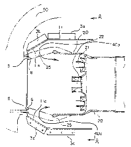
described with reference to Figs. 2 to 6. Fig. 2 is a cross
sectional view showing a fitting state of a rectifier tube of
gas turbine combustor of the first embodiment, Fig. 3 is a cross
sectional view taken on line A-A of Fig. 2, and Fig. 4 is a
- 31 -
CA 02288555 1999-11-04
perspective view of the rectifier tube of Fig. 2. In Fig. 2,
a combustor 20 is contained in a turbine cylinder 50 and a
plurality of stays 25 are fitted to around an outer periphery
of an inner tube 28 with a predetermined interval being kept
between each of the stays 25. A rectifier tube 11 is provided
so as to surround and cover the stays 25 with a predetermined
space being kept between itself and the inner tube 28 or the
stays 25, said rectifier tube 11 at its fitting flange 5 being
fitted fixedly by a bolt 6 to the turbine cylinder 50 side near
end portions of the stays 25.
In Fig. 3, the rectifier tube 11 is made by combining
a cylinder 1 and a cylinder 2 both of a semi-circular cross
sectional shape. The cylinder 1 is provided with flanges 3a,
3b, 3c, 3d (see Fig. 2 ) and the cylinder 2 is likewise provided
with flanges 4a, 4b, 4c, 4d (4b and 4d are omitted in the
illustration). These flanges are jointed together by bolts and
nuts 7 to form the rectifier tube 11 of a circular cross
sectional shape, wherein the flanges 3a and 4a, 3b and 4b, 3c
and 4c, 3d and 4d are jointed together, respectively.
The fitting flange 5 of the rectifier tube 11 is made
in plural pieces arranged around one end of the rectifier tube
11 of the cylindrical shape, as shown in Fig. 3. The other end
of the rectifier tube 11 opens as an opening of air inflow side.
The fitting flange 5 side of the rectifier tube 11 opens also
and main fuel nozzles 21 and a pilot fuel nozzle 22 are inserted
- 32 -
CA 02288555 1999-11-04
through this opening portion. An outside view of only the
rectifier tube 11 so constructed is shown in Fig. 4.
In the gas turbine combustor so constructed, air 40a,
40b coming from a compressor flows around the inner tube 28 of
the combustor 20 through the predetermined space between the
inner tube 28 and the rectifier tube 11 and is turned to be
rectified by and around a sloping portion lla of the rectifier
tube 11 wherein a diameter of the rectifier tube 11 contracts
gradually along the air flow direction. Thus, the air 40a, 40b
so rectified flows through gaps formed by the stays 25 to flow
into the inner tube 28 uniformly.
As there had been no such rectifier tube 11 in the
prior art, the air flowing around the combustor 20 flows in
through the gaps of the stays 25 from a comparatively wide space
formed between an inner wall of the turbine cylinder 50 and the
combustor 20 and there is a wide space or narrow space in that
space according to the place where the air flows, hence the air
hardly flows uniformly therein.
On the contrary, in the present embodiment, there is
covered and kept the predetermined space by the rectifier tube
11 around the gaps of the stays 25 through which the air flows
and the air whose pressure and velocity are kept constant flows
into this space to further flow into the combustor 20 through
the gaps of the stays 25, and further the air flow is rectified
smoothly of its flow direction by the sloping portion of the
- 33 -
CA 02288555 1999-11-04
rectifier tube 11 to flow into the combustor 20 uniformly, thus
there occurs no biased flow of the air coming into the inner
tube 28 and a uniform fuel concentration is attained at nozzle
outlet portions of the combustor 20, thereby NOX production can
be suppressed.
Fig. 5 is a cross sectional view of an example where
the rectifier tube 11 of the first embodiment is applied to
another type, or a hat top type, of combustor. In Fig. 5, an
outer tube casing 51 is provided projecting toward outside from
a turbine casing 50 to form a fitting portion of an inner tube
of the combustor. Such a combustor fitting structure is
generally called a top hat type, wherein stays 25 support the
inner tube 28 around main fuel nozzles 21 of the combustor and
the outer tube casing 51 and an outer tube casing cover 51a
surround to cover the stays 25. Such outer tube casing 51 is
arranged projecting around a rotor in the same number of pieces
as the combustor to form an extension portion of the turbine
casing 50.
The rectifier tube 11 is of a cylindrical shape
divided into two portions as mentioned above. The rectifier
tube 11 is provided with a plurality of fitting flanges 5
arranged circularly with a predetermined interval between each
of the fitting flanges 5 and is fitted to an inner tube fitting
flange 52 by bolts 6 via the fitting flanges 5. A sloping
portion lla is formed so as to connect to the fitting flanges
- 34 -
CA 02288555 1999-11-04
5. The rectifier tube 11 is provided coaxially with a combustor
central axis 60 and covers an air intake space keeping a gap
so as not to come in contact with an inner wall surface of the
outer tube casing 51 and keeping a uniform dimension of space
around the stays 25.
In the combustor constructed as above, air 80 coming
from a compressor flows in through an opening portion of the
rectifier tube 11 to become a uniform flow 80a in the space
between the rectifier tube 11 and the inner tube 28 and then
turns in the space formed by the sloping portion lla and the
stays 25 to flow into the combustor as a turning flow 80b. In
this turning flow 80b, as the uniform flow 80a comes in there
along the sloping portion lla of the rectifier tube 11, the flow
turns smoothly to enter swirler portions in the space of the
combustor, thereby a uniform swirled flow is produced and
combustion performance is enhanced.
Fig. 6 is a cross sectional view of another example
where the rectifier tube 11 of the first embodiment is applied
to still another type of combustor wherein the top hat
structural portion of the combustor is divided. That is, an
outer tube casing 151 is fitted with an outer tube casing cover
151a detachably by a bolt 152 so that when the bolt 152 is
unfastened, the outer tube casing cover 152 together with the
combustor may be taken out.
In Fig. 6, the rectifier tube 11 is constructed to
- 35 -
CA 02288555 1999-11-04
be fitted to the outer tube casing cover 151a via a fitting
flange 5 and an inner tube fitting flange 52 integrally by a
bolt 16. In this construction, there is needed no exclusive
bolt for fitting the rectifier tube 11, thereby the structure
of the fitting portion can be simplified. Other portions of
the construction being same as those of Fig. 5, same effect as
that of the example of Fig. 5 can be obtained.
Next, a second embodiment in the (X-2 ) portion of the
combustor of Fig. 1 will be described with reference to Figs.
7 to 10. Fig. 7 is a side view of an inner tube portion of
combustor of the second embodiment. In Fig. 7, a high
temperature combustion gas 161 flows into an inner tube 28, said
high temperature combustion gas being produced by combustion
of fuel injected from a pilot fuel nozzle and main fuel nozzles
and air. In an circumferential surface of the inner tube 28,
there are provided air holes 10-1 on an upstream side of the
inner tube 28, said air holes 10-1 having six pieces of air holes
arranged with equal intervals around the inner tube 28. Also,
there are provided air holes 10-2 downstream of the air holes
10-1, having six pieces of air holes with equal intervals.
Arrangement of these air holes 10-1, 10-2 is same as that of
the prior art case shown in Fig. 23. In the present embodiment,
air holes 10-3 on a downstream side of the inner tube 28 have
only three pieces of air holes, less than six in the prior art
case, around the inner tube 28.
- 36 -
CA 02288555 1999-11-04
Fig. 8 is a cross sectional view showing arrangement
of the air holes 10-3, wherein Fig. 8(a) is a view taken on line
B-B of Fig. 7 and Fig. 8 (b) is a view showing a modified example
of the air holes 10-3 . In Fig. 8 ( a ) , there are provided three
pieces of air holes 10-3a, 10-3b, 10-3c with equal intervals
in the circumferential surface of the inner tube 28. In Fig.
8(b), six pieces of air holes 10-3a, 10-3b, 10-3c, 10-3d, 10-3e,
10-3f as provided in the prior art are seen and in order to
arrange the air holes in three pieces with equal intervals, the
air holes 10-3b, 10-3d, 10-3f are closed by plugs 14 with the
air holes 10-3a, 10-3c, 10-3e only remaining opened and the same
arrangement of three pieces of the air holes as that of Fig.
8(a) is formed.
Fig. 9 is a cross sectional view taken on line C-C
of Fig. 8(b) . In Fig. 9, the plug 14, being of a diameter which
is slightly smaller than a hole diameter of the air hole 10-3b,
has a flange 14a around a peripheral portion thereof and is
fitted in the air hole 10-3b to be fixed by welding, etc. for
close of the hole. By use of such plug 14, the inner tube as
existing can be used as it is and, when so modified, can have
the construction of the present second embodiment easily.
In the second embodiment constructed as above, the
air entering the combustor 20 comprises three portions, like
in the prior art case, that is, the air used for combustion at
the nozzle portion, the air entering the inner tube for cooling
- 37 -
CA 02288555 1999-11-04
thereof through the small cooling holes and the air flowing into
the inner tube through air holes 10-1, 10-2, 10-3. Where the
total quantity of the air is 100, the quantity of the air
flowing through the air holes 10-1, 10-2 is about 14$,
respectively, like in the prior art case, and that of the air
flowing through the air holes 10-3, having only the three holes
as compared with the six holes in the prior art, is suppressed
to about 7 to 12~.
If the respective air quantities of the air holes 10-1,
10-2, 10-3 are expressed in ratio, it is approximately 1:1: ( 0 . 5
to 0.85), and as compared with the ratio in the prior art of
1:1 : ( 1 . 3 to 1 . 4 ) , the air quantity entering the inner tube from
the air holes 10-3 of the downstream side of the inner tube is
reduced approximately to the half. As the result of this, an
appropriate air quantity is realized such that while the air
131 entering through the air holes 10-3 of the downstream side
of the inner tube is sufficient to be used for combustion of
carbon remaining unburnt in the high temperature combustion gas
161, it is not so much as to cool the high temperature combustion
gas 161. Thus, combustion efficiency is enhanced and
occurrence of a dark colored smoke in the exhaust gas can be
prevented.
Fig. 10 is a graph showing a relation between smoke
visibility and load as an effect of the second embodiment as
compared with the prior art case. In Fig. 10, the horizontal
- 38 -
CA 02288555 1999-11-04
axis shows load and the vertical axis shows value of a level
of smoke visibility (BSN). As this value becomes larger, it
means a thicker smoke color to be visible by human eyes and as
this value becomes smaller, it means a thinner smoke color to
be less visible. According to the result thereof, it is
understood that smoke color X1 of the combustor of the present
embodiment is thinner than that XZ of the combustor in the prior
art shown in Fig. 23 and there is obtained an effect to suppress
occurrence of the smoke.
Next, a third embodiment in the (X-3 ) portion of the
combustor of Fig. 1 will be described with reference to Figs.
11 to 14. Fig. 11 is a partial cross sectional view of a main
swirler of combustor of the third embodiment. In Fig. 11, a
combustor 20 in its central portion has a pilot swirler 31 and
a pilot cone 33 arranged at an end portion thereof and eight
pieces of main swirlers 32 are arranged around the pilot swirler
31. These swirlers 31, 32 are fitted to a base plate 34 of
circular shape and the base plate 34 has its circumferential
periphery welded to an inner wall of the combustor 20. This
structure is same as that existing in the prior art. A block
17 is fitted to an outer circumferential surface of an end
portion of the main swirler 32 and the main swirler 32 is fixed
to the inner wall of an end portion of the combustor 20 via the
block 17, wherein the block 17 is fixed to the inner wall of
the combustor 20 by a bolt 12, which passes through the wall
- 39 -
CA 02288555 1999-11-04
of the combustor from outside, via a washer 13.
Fig. 12 is an enlarged view of portion D of Fig. 11.
The block 17 is fitted to the main swirler 32 by welding. A
fitting seat 36a is formed by cladding welding on the inner wall
of an end portion 36 of the combustor 20 and a recess portion
36b for receiving the washer 13 is formed in an outer wall of
the combustor 20 at a position corresponding to the fitting seat
36a. A bolt hole is bored there and the bolt 12 is screwed into
the block 17 for fixing thereof via the washer 13, thereby the
main swirler 32 is fixed to the combustor 20.
Fig. 13 is a partial view seen from plane E-E of
Fig. 11. The block 17 is fitted by welding to the outer
circumferential surface each of the main swirlers 32 arranged
in eight pieces and each of the blocks 17 is fixed to the wall
of the end portion 36 of the combustor 20 by two bolts 12.
The two bolts 17 are screwed into the block 17 via one common
washer 13.
Fig. 14 is a detailed view of portion F of Fig. 13,
wherein the bolts 12 and the washer 13 are shown being enlarged.
The recess portion 36b is formed not in a curved form but in
a linear form in the outer circumferential surface of the end
portion 36 of the combustor 20 and the washer 13 is made in a
flat plate of linear shape. The two bolts 12 are inserted into
bolt holes 36c which are bored in parallel with each other to
be screwed into the block 17 for fixing thereof and thus for
- 40 -
CA 02288555 1999-11-04
fixing the main swirler 32 to the combustor 20. An anti-
rotation welding 18 is applied to the bolt 12 for preventing
rotation or loosening thereof. By employing such structure,
manufacture of the bolt fitting portion is simplified and as
the washer 13 makes contact with the recess portion 36b via flat
surfaces, a good effect against rotation or loosening of the
bolt is obtained. Further, the accuracy in the work process
or in the fitting can be enhanced.
In the prior art gas turbine combustor, as described
before, cracks often occur in the welded portion of the fixing
metal member 35 supporting the main swirler 32 due to vibration,
thermal stress, etc. in operation and the structure itself is
the welded structure of thin metal plates so that there is a
problem in the accuracy of fitting and assembling. Further,
deformation occurs due to residual strain in the welded portion
and the metal plates, which causes mutual contact of the main
swirler 32 and the main fuel nozzle arranged therein to increase
abrasion thereof. Also, there is only a narrow working space
around the fitting portion of the fixing metal member 35, which
requires a high skill for performing a satisfactory welding.
According to the structure of the present third
embodiment, the main swirler 32 is fixed to the combustor 20
by the bolt 12 via the washer 13 and the block 17 fixed to the
main swirler 32, thereby accuracy of the assembling is enhanced,
strain due to welding does not occur and welding work in the
- 41 -
CA 02288555 1999-11-04
narrow space becomes unnecessary. Also, the washer 13 of flat
plate shape makes contact with the recess portion 36b and the
two bolts 12 fixes the main swirler 32 to the combustor 20,
thereby no loosening of the bolt 12 occur and a precise
positioning becomes possible. Further, maintenance of
replacement of parts. etc. becomes simple, so that all the
mentioned problems are improved.
Next, a fourth embodiment in the (X-4 ) portion of the
combustor of Fig. 1 will be described with reference to Figs .
15 to 17. Fig. 15 is a cross sectional side view showing a
fitting portion of a pilot cone in the combustor in contrast
with the prior art case shown in Fig. 24. Fig. 16 is a detailed
view of portion G of Fig. 15 in contrast with the prior art case
shown in Fig. 26.
In Figs. 15 and 16, a pilot swirler 31, a pilot cone
33, a main swirler 32, a base plate 39, a fitting member 39b
and a cone ring 38, respectively, have the same functions as
those of the prior art shown in Figs. 24 and 26, hence same
reference numerals are used with description thereon being
omitted, and featured portions of the present invention being
configuration portions shown by numerals 31a, 33a and welded
portions of X1 to X4, they will be described in detail below.
In Fig. 16, as to a pilot swirler end portion 31a,
while it is structured in the prior art to be inserted into an
end portion of the pilot cone 33 in contact with an inner
- 42 -
CA 02288555 1999-11-04
circumferential surface of the pilot cone 33, that of the
present invention is structured to be inserted into the
cylindrical portion 39a of the base plate 39. For this purpose,
a pilot cone end portion 33a is made shorter as compared with
the prior art case and an outer diameter of the pilot cone end
portion 33a is made approximately same as that of the pilot
swirler end portion 31a so that both ends of the pilot cone end
portion 33a and the pilot swirler end portion 31a are welded
together in contact with each other.
In the welded structure mentioned above, as fitting
work procedures thereof, the pilot swirler 31 is first inserted
into the cylindrical portion 39a of the base plate 39 to be fixed
to an end of the cylindrical portion 39a by welding X1 done along
the circumferential direction. Then, the cone ring 38 is fitted
to the fitting member 39b, which is made integrally with the
base plate 39, by welding X~ done along the circumferential
direction. Then, while the pilot cone end portion 33a and the
pilot swirler end portion 31a make contact with each other, the
pilot cone 33 is fitted to the cone ring 38 by welding X3 and
thereafter the pilot cone end portion 33a and the pilot cone
33 are jointed together by welding X4 which is done from inside
of the pilot cone 33 along the circumferential direction. It
is to be noted that the welding X" X4 may be done in the reverse
order, that is, the welding X4 is earlier and the welding X3
is later and also that a black arrow in Fig. 16 shows a direction
- 43 -
CA 02288555 1999-11-04
in which the welding X4 is done.
According to the welded structure mentioned above,
in case of repairing work, the welding X4 is removed from inside
of the pilot cone 33 and the welding X3 at a pilot cone outlet
is also removed, thereby the pilot cone 33 can be detached
easily. In the prior art case, there is no sufficient work space
in the portion of the welding X" X, (Fig. 26) and moreover there
is a difficulty in detaching the pilot cone 33 unless the entire
portion of the base plate block is disassembled. In the present
fourth embodiment, however, accuracy of the welded structure
is enhanced, thereby welding strength can be enhanced and
workability in the repairing can be improved remarkably.
Fig. 17 is an enlarged detailed view of the welded
fitting structures of the pilot cones of the prior art and of
the present fourth embodiment, wherein Fig. 17(a) is of the
prior art and Fig. 17 (b) is of the fourth embodiment. In both
of Figs . 17 ( a ) and 17 ( b ) , while the pilot cone end portion 33a
is made long enough to be inserted into the cylindrical portion
39a of the base plate 39 in the prior art, that 33a of the present
embodiment is made shorter to abut on the pilot swirler end
portion 31a.
By this structure, the pilot cone 33 of Fig. 17(b)
is supported by the base plate 39 via the welding X4 of the pilot
swirler 31 and it is understood that detachment of the pilot
cone 33 is done easily if the welding X4 is removed by the work
- 44 -
CA 02288555 1999-11-04
done from inside of the pilot cone 33, as shown by a black arrow
of Fig. 17(b).
According to the present fourth embodiment as
described above, the welded structure is employed such that the
pilot swirler 31 is first fitted to the base plate and the pilot
cone 33 is fitted thereafter, and also the welding X4 therefor
is done from inside of the pilot cone 33, thereby repairing work
and detachment of the pilot cone 33 become easy to improve the
workability remarkably. Thus, a lot of labor and time for
repairing can be saved, accuracy of the welding is enhanced as
well and strain due to the thermal stress can be suppressed to
the minimum.
Next, a fifth embodiment in the (X-5) portion of the
combustor of Fig. 1 will be described with reference to Fig.
18. Fig. 18 is a cross sectional view of a steam cooled
structure of a combustor tail tube outlet portion of the fifth
embodiment. This steam cooled structure is applicable to the
outlet portion of the tail tube 24 shown in Fig. 27, and the
structure of Fig. 18 is shown in contrast with that of the prior
art shown in Fig. 29.
In Fig. 18, like in the prior art case, a multiplicity
of steam passages 150 are provided in a wall 20a of the tail
tube outlet portion and a cavity 75 is formed in an entire inner
circumferential peripheral portion of a flange 71 of the tail
tube outlet portion. A manifold 73 and a hollow 77 are formed
- 45 -
CA 02288555 1999-11-04
being covered circumferentially by a covering member 72 between
an outer surface portion of the wall 20a of the tail tube outlet
portion and the flange 71 and being partitioned by a rib 76
between each other. The manifold 73 communicates with a cooling
steam supply pipe ( not shown ) and the hollow 77 has air layer
formed therein.
In the mentioned cooled structure, cooling steam 132
supplied into the manifold 73 from the cooling steam supply pipe
flows into the steam passages 150 through a steam supply hole
74 to cool the wall 20a which is exposed to a high temperature
combustion gas of about 1500°C. Also, the steam entering the
cavity 75 cools end portions 20b, 20c. The end portion 20b
cooled by the steam in the cavity 75 is exposed on a side surface
of the flange 71 to air of about 400 to 450°C in a turbine
cylinder. The end portion 20c is exposed to the air layer in
the hollow 77 and is not directly exposed to the cooling steam
132. While this end portion 20c is directly exposed to the
cooling steam 132 to be cooled excessively in the prior art,
such an excessive cooling is prevented in the present fifth
embodiment.
According to the fifth embodiment as described above,
the wall 20a of the tail tube outlet portion to be directly
exposed to the high temperature combustion gas 161 is cooled
sufficiently by the cooling steam 132 supplied into the steam
passages 150 from the manifold 73 through the steam supply hole
- 46 -
CA 02288555 1999-11-04
74. On the other hand, while the steam entering the cavity 75
of the end portion of the tail tube outlet cools the wall exposed
to the high temperature combustion gas 161, the end portion 20c
which is not directly exposed to the high temperature
combustion gas 161 is not cooled. This end portion 20c makes
contact with the air layer in the hollow 77 and is not cooled
excessively. Thus, the differential temperature between the
inner circumferential wall surface and the outer
circumferential structural portion in the tail tube outlet
portion is mitigated and the thermal stress is alleviated.
It is to be noted that although the present fifth
embodiment is described with respect to the example shown in
Fig. 27 where the steam is supplied from the cooling steam
supply pipe 127 of the tail tube outlet portion and from the
cooling steam supply pipe 125 on the combustion tube side and
is recovered into the steam recovery pipe 126, supply and
recovery of the steam may be done reversely, that is, the steam
is supplied from the pipe 126 and is recovered into the pipes
125, 127 and in this case also, the same effect can be obtained.
~ Next, a gas turbine combustor of a sixth embodiment
will be described with reference to Fig. 19. In Fig. 19, a
combustor 20 is generally formed in a cylindrical shape and a
pilot fuel nozzle 22 for supplying pilot fuel is provided in
a liner 212 along a central axis O of the combustor 20. A pilot
air supply passage 216 is provided around the pilot fuel nozzle
- 47 -
CA 02288555 1999-11-04
22 and a pilot swirler 31 for holding pilot flame is provided
in the pilot air supply passage 216. Thus, the pilot fuel nozzle
22, the pilot air supply passage 216 and the pilot swirler 31
compose a pilot burner. Downstream of the pilot air supply
passage 216, there is provided a pilot cone 33 for forming a
pilot combustion chamber 224.
A main fuel nozzle 21 for supplying main fuel and a
main air supply passage 222 are provided around the pilot air
supply passage 216. A main swirler 32 is provided in the main
air supply passage 222. Thus, the main fuel nozzle 21, the main
air supply passage 222 and the main swirler 32 compose a main
burner. Between the pilot air supply passage 216 and the main
air supply passage 222, there is provided an exhaust gas supply
passage 218 as a supply passage of shield gas . Downstream of
the exhaust gas supply passage 218 and on the outer side of the
pilot cone 33, a sub-cone 226 is provided coaxially with the
pilot cone 33. Numeral 218a designates a swirler provided in
the exhaust gas supply passage 218.
Function of the present embodiment will be described
below. Pilot air supplied from the pilot air supply passage
216 enters the pilot combustion chamber 224 to flow surrounding
pilot fuel supplied from the pilot fuel nozzle 22, thereby the
pilot fuel together with the pilot air burns to form the pilot
flame (a white arrow 230) comprising diffusion flame. Main fuel
supplied from the main fuel nozzle 21 and main air supplied from
- 48 -
CA 02288555 1999-11-04
the main air supply passage 222 are mixed together in a mixing
chamber 228 downstream thereof to form a premixture shown by
arrow 232. This premixture 232 comes in contact with the pilot
flame 230 to form premixture flame as main flame 234.
In the present gas turbine combustor 20, exhaust gas
produced by the combustion is supplied into a gas turbine ( not
shown ) provided downstream of the combustor 20 for driving the
gas turbine. After having driven the gas turbine, the exhaust
gas is mostly discharged into the air, but a portion thereof
is recirculated into the exhaust gas supply passage 218 of the
combustor 20 via a recirculation system including an exhaust
gas compressor, etc. (not shown).
The exhaust gas 236 supplied from the exhaust gas
supply passage 218 flows through an exhaust gas leading portion
as a leading portion of shield gas formed between the pilot cone
33 and the sub-cone 226 to be supplied between the pilot flame
230 and the premixture 232. Thus, mutual contact of the pilot
flame 230 and the premixture 232 is suppressed by the exhaust
gas 236 so supplied, thereby combustion velocity of the main
flame 234 is reduced and the main flame 234 becomes longer in
the combustor axial direction or in the main flow direction.
Hence, combustion energy concentration released by the main
flame 234 or cross sectional combustion load of the combustor
becomes reduced, exciting force of the combustion vibration is
reduced and combustion vibration is suppressed. Further, due
- 49 -
CA 02288555 1999-11-04
to existence of the exhaust gas 236, oxygen concentration in
the main flame 234 is reduced and flame temperature is reduced,
thereby NOX quantity produced is reduced.
It is to be noted that although an example to use the
exhaust gas of the gas turbine is described in the present
embodiment, the invention is not limited thereto but exhaust
gas from other machinery or equipment may be used, or inert gas,
such as nitrogen, supplied from other facilities may be used
in place of the exhaust gas . The point therefor is to use gas
which is inert with respect to combustion reaction so as to be
able to prevent direct contact of the mixture and the pilot
flame and to elongate the premixture flame in the main flow
direction in the combustor.
While various embodiments are described with
reference to figures, it is understood that the invention is
not limited to the particular construction and arrangement of
parts and components herein illustrated and described, but
embraces such modified forms thereof as come within the scope
of the appended claims.
- 50 -