Language selection

Search

Patent 2288826 Summary

Third-party information liability

Some of the information on this Web page has been provided by external sources. The Government of Canada is not responsible for the accuracy, reliability or currency of the information supplied by external sources. Users wishing to rely upon this information should consult directly with the source of the information. Content provided by external sources is not subject to official languages, privacy and accessibility requirements.

Claims and Abstract availability

Any discrepancies in the text and image of the Claims and Abstract are due to differing posting times. Text of the Claims and Abstract are posted:

  • At the time the application is open to public inspection;
  • At the time of issue of the patent (grant).
(12) Patent: (11) CA 2288826
(54) English Title: MOLDING APPARATUS HAVING AN IMPROVED FASTENING MEANS OF THE PERIPHERAL DIES TO THE CORE
(54) French Title: MOULE POSITIF
Status: Expired and beyond the Period of Reversal
Bibliographic Data
(51) International Patent Classification (IPC):
  • B29C 43/36 (2006.01)
  • B29C 33/20 (2006.01)
  • B29C 33/30 (2006.01)
(72) Inventors :
  • LICHTINGER, PETER (Germany)
(73) Owners :
  • KRAUSSMAFFEI TECHNOLOGIES GMBH
(71) Applicants :
  • KRAUSSMAFFEI TECHNOLOGIES GMBH (Germany)
(74) Agent: SMART & BIGGAR LP
(74) Associate agent:
(45) Issued: 2007-06-26
(86) PCT Filing Date: 1999-02-26
(87) Open to Public Inspection: 1999-09-10
Examination requested: 2003-10-17
Availability of licence: N/A
Dedicated to the Public: N/A
(25) Language of filing: English

Patent Cooperation Treaty (PCT): Yes
(86) PCT Filing Number: PCT/EP1999/001269
(87) International Publication Number: EP1999001269
(85) National Entry: 1999-11-02

(30) Application Priority Data:
Application No. Country/Territory Date
198 09 720.4 (Germany) 1998-03-06

Abstracts

English Abstract


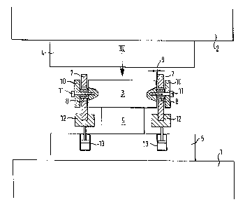
A positive mold is described with a core (3) and a female mold member (4) as
well as wraparound peripheral dies (7), which are attached to the core for
movement in closing direction and completely surround the core (3). In the
region
of the impact areas of the peripheral dies (7) upon the female mold member
(4),
the impacting surfaces are configured complementary, for example planar. The
invention is characterized by the fact that each peripheral die (7) is
attached
laterally to the core by at least one spacer and retaining element (8, 10),
with the
spacer element (8) being slightly greater than the cross section of the
peripheral
die, so that a small gap (9) of preferably between 0.01 mm and 0.02 mm is
formed. The fixed tolerance gap offers the advantage that constant, minimum
frictional conditions exist. The lateral attachment facilitates the
replacement of
individual peripheral dies (7) and temperature-based dimensional changes of
the
core (3) are followed by the peripheral dies, without risk of jamming.


French Abstract

L'invention concerne un outil à bords plongeants comprenant une âme (3), une matrice (4) et des baguettes de bordure plongeante (7) appliquées sur la circonférence de l'âme (3) de façon mobile dans le sens de fermeture et qui entourent complètement l'âme. Dans la zone des faces de butée des baguettes de bordure plongeante (7) contre la matrice (4), les surfaces qui se rencontrent ont une forme correspondante, par exemple, plate. L'invention est caractérisée en ce que chaque baguette de bordure plongeante (7) est fixée sur le côté de l'âme à l'aide au moins d'un élément d'écartement et de maintien (8, 10). L'élément d'écartement (8) est légèrement plus long que la section transversale de la baguette de bordure plongeante de façon à obtenir une petite fente (9) comprise, de préférence, entre 0,01 mm et 0,02 mm. Cette fente de tolérance fixe présente l'avantage de rapports de frottement minimaux constants. La fixation latérale facilite le remplacement des différentes baguettes de bordure plongeante (7). De plus, les baguettes de bordure plongeante (7) suivent les modifications dimensionnelle de l'âme (3) dues à la température suivent sans risque de coincement.

Claims

Note: Claims are shown in the official language in which they were submitted.


CLAIMS:
1. A molding apparatus; comprising:
a female mold member;
a core capable of moving in a closing direction
against the female mold member to define a cavity for
molding an object, said core being completely surrounded by
peripheral dies which are movable in the closing direction
against a complementary impact area of the female mold
member; and
fastening means for securing each of the
peripheral dies laterally to the core, said fastening means
including a retaining element for attaching the peripheral
die to the core, and a spacer element fitted in the
peripheral die and having a width which slightly exceeds a
cross section of the peripheral die to thereby realize a gap
between confronting surfaces of the core and the peripheral
die.
2. The molding apparatus of claim 1 wherein the gap
has a width of less than 0.05 mm.
3. The molding apparatus of claim 1 wherein the gap
has a width ranging between 0.01 mm and 0.02 mm.
4. The molding apparatus of claim 1 wherein the
spacer element is a sleeve, said retaining element being
secured with a fastener to the core, said fastener being
surrounded in a space between the retaining element and the
core by the spacer element.
5. The molding apparatus of claim 1 wherein the
spacer element and the retaining element are configured in
one piece in the form of a T shaped sliding block, said
9

peripheral die having a recess for engagement by the sliding
block.
6. The molding apparatus of claim 1, and further
comprising operating means for moving the peripheral dies
relative to the core.
7. The molding apparatus of claim 6 wherein the
operating means includes at least one of hydraulic piston-
cylinder unit and pneumatic piston-cylinder unit.
8. The molding apparatus of claim 1, and further
comprising spring means, positioned at a core-proximal side
of the peripheral dies, for biasing the peripheral dies in
the direction of the female mold member.
9. The molding apparatus of claim 8 wherein the
spring means includes an annular spring.
10. The molding apparatus of claim 1, and further
comprising a support frame, encircling the core, for
attachment of the peripheral dies.
11. The molding apparatus of claim 10, and further
comprising a movable mold clamping plate for attachment of
the core, a core plate secured to the movable clamping plate
and provided for support of the core; spring means,
positioned at a core-proximal side of the peripheral dies,
for biasing the peripheral dies in the direction of the
female mold member; and operating means for moving the
peripheral dies relative to the core, at least one of said
operating means and said spring means being mounted between
the support frame and the core plate.
12. The molding apparatus of claim 11 wherein the
support frame engages behind the core, at least one of the
10

operating means and spring means positioned precisely below
the peripheral dies.
13. The molding apparatus of claim 11 wherein the
peripheral dies are formed in a region bearing on the core
with channels, and the core is formed with complementary
channels, with the channels of the peripheral dies extending
to an area close to the core so that a movement of the
peripheral dies in the closing direction results in a slight
elevation of a finished molded plastics part, with gas
supplied via the channels.
14. The molding apparatus of claim 1 wherein the
female mold member is of flat configuration at least in the
area of impact of the peripheral dies.
15. A use of a molding apparatus according to one of
the claims 1 to 14 for the manufacture of plastic panes of
side windows for motor vehicles.
11

Description

Note: Descriptions are shown in the official language in which they were submitted.


CA 02288826 2006-12-21
31254-2
MOLDING APPARATUS HAVING AN IMPROVED FASTENING MEANS
OF THE PERIPHERAL DIES TO THE CORE
The invention relates to a positive.mold.
FIG. 1 shows a cross sectional illustration of a positive mold known in the
prior
art and comprised of a female mold member and a core which descends into the
female mold member. Guidance of the core and sealing of the cavity is realized
by circumferential peripheral dies. Conventional positive molds suffer the
following drawbacks:
Damage of the descending dies on both mold halves (injection side and ciosing
side) as a result of:
- imprecise centered descent of the core side into the female mold member;
- too narrow dimensions of the female mold member as a consequence of
mold shrinkage caused by temperature decrease below the very narrow
temperature tolerances;
- one-sided contact of the descending dies as a consequence of a floating
effect which is encountered during compression injection molding and
cannot be offset by greater machine tolerances;
- excessive core dimension as a consequence of a mold dilatation caused
by temperature deviation above the very narrow temperature tolerances.
1

CA 02288826 1999-11-02
The stated drawbacks can be eliminated by known molds in which the core is
provided with one or more circumferential peripheral dies which are mounted to
the core and movable in closing direction and which are able to bear upon flat
areas of the female mold member in closed state. U.S. Pat. No. 4,707,321
discloses such a mold for making optical data carriers, with the mold having a
circular core which is circumscribed by a circular peripheral die which can be
moved by compressed air along the core in direction of the female mold member.
The peripheral die is hereby formed in one piece in accordance with the
diameter
of the circular injection molded part. This peripheral die is unsuitable for
use with
differently designed injection molded parts. The closest prior art according
to
"Patent Abstracts of Japan, Publication Number 08057922 A" discloses a
positive
mold with several peripheral dies which wrap around the core and are mounted
to the core for movement in closing direction and completely surround the
core.
Each individual peripheral die is received in a T-shaped groove which is
continuous around the entire circumference of the marginal region of the core
and open toward the side of the female mold member and which is formed of two
pieces in radial direction. In order to realize a close fit of each peripheral
die in
this groove, without jamming, but yet being shiftable along the core, both
halves
of each peripheral die are moved apart by spring elements so as bear upon
confronting inside surfaces of the groove. Provided in the bottom of the
groove
are spring elements by which the peripheral dies are retained in the direction
of
the female mold member under prestress. When the mold is closed, the
peripheral die, jutting out from the groove, is pressed against the female
mold
2

CA 02288826 2006-12-21
31254-2
member which has a flat configuration in the contact area of
the peripheral die. This positive mold is configured in a
comparably complex manner, and a replacement of defective or
worn-off peripheral dies requires a considerable effort. A
further drawback resides in the fact that the inner part of
the peripheral die is pushed outwards when high injection or
stamping pressures are applied, so that the plastic mass can
escape and/or flashes are encountered on the injection
molded part. This could be avoided when sufficiently
biasing the bottom spring. However, this in turn is
accompanied by the drawback that the peripheral die can be
moved in the T-groove only at great difficulty or can even
jam.
Thus, it is the object of the present invention to
improve the conventional mold in such a manner that the
advantages of conventional positive molds according to
FIG. 1 are maintained while yet the mold overall has a
simpler configuration and allows in particular an easy
replacement of individual peripheral dies.
According to an aspect of the invention, there is
provided a molding apparatus; comprising: a female mold
member; a core capable of moving in a closing direction
against the female mold member to define a cavity for
molding an object, said core being completely surrounded by
peripheral dies which are movable in the closing direction
against a complementary impact area of the female mold
member; and fastening means for securing each of the
peripheral dies laterally to the core, said fastening means
including a retaining element for attaching the peripheral
die to the core, and a spacer element fitted in the
peripheral die and having a width which slightly exceeds a
cross section of the peripheral die to thereby realize a gap
3

CA 02288826 2006-12-21
31254-2
between confronting surfaces of the core and the peripheral
die.
The main advantage of an aspect of the present
invention resides in the particular configuration of the
securement of the peripheral dies to the core. The lateral
attachment with spacer and retaining elements allows, on the
one hand, a displacement of the peripheral dies along the
core, and, on the other hand, the attachment and detachment
of the peripheral dies from the core can be executed in a
simpler manner. The fixed
3a

CA 02288826 2006-12-21
31254-2
tolerance gap results in constant, minimum frictional conditions, thereby
significantly enhancing the availability of the moid. A jamming of the
peripheral
dies upon the core is prevented even at comparably great temperature
fluctuations, because the inventive lateral attachment realizes that the
peripheral
dies simply "follow" temperature-based dimensional changes of the core.
Aspects of the invention have the following further advantages:
- Maintaining a circumferential constant gap of less than
0.05 mn and preferably about 0.01 to 0.02 nm, independent of:
- temperature fluctuations of the mold or intended terriperature changes;
- independent of the machine-guide tolerances;
- independent of the component dimensions and mold dimensions;
- very high availability of the mold;
- no flash removal or re-finishing operations of the edges of the plastic
parts
are necessary.
The invention will now be described in more detail with reference to FIGS. 2
to 4.
It is shown in:
FIG. 1: a positive mold according to the prior art
FIG. 2: a cross section of a positive mold according to the invention
4

CA 02288826 2006-12-21
31254-2
FIG. 3: a top view of the positive mold according to the invention from a
perspective of the female mold member, i.e. in the direction of the arrow
in FIG. 2
FIG. 4: a detailed illustration of the positive mold according to FIGS. 2 and
3.
Preferred field of application of the positive mold according to the invention
is the
manufacture of plastic panes, as used, for example, as side panes for
passenger
cars. The invention is, however, not limited thereto, but applicable in
general to
the manufacture of formed parts with positive molds, i.e., in general,.
through
compression injection molding.
According to FIG. 2, a core 3 and a female mold member 4 are fastened onto a
movable mold clamping plate 1 and a fixed mold clamping plate 2 of a machine
for molding plastics. The core 3 is secured to the movable mold clamping plate
1
via a backing plate 5 and a core receiving plate 6. Displaceable continuously
in a
sealing manner about the core 3 are wraparound peripheral dies 7. This is
realized by placing in recesses of the peripheral dies 7 spacer sleeves 8
which
are slightly greater in width than the cross section of the peripheral dies 7.
Thus, a srrall gap 9 is fo=ed which is in the range frcn 0.01 rrm to 0.02 mn.
The
circumferential assembly of the peripheral dies 7 upon the core 3 is
implemented
by retaining elements 10 which are tightly pressed against the spacer sleeves
8
by means of fastening screws 11 turned into the core. This assembly ensures
5

CA 02288826 1999-11-02
that irrespective of the heat expansion or cold shrinkage, a same gap mass is
always precisely maintained. As the peripheral dies 7 do not descend into the
opposing female mold member 4, a jamming or tilting is prevented, regardless
of
the temperature. Depending on the molded part being fabricated, the peripheral
dies 7 are made of several pieces. The peripheral dies 7 are mounted on a
support frame 12 extending continuously about the core 3, so that a heat
expansion or a cold shrinkage of the core 3 (or of the support frame 12)
results in
a relative movement between the peripheral dies 7 and the support frame 12. In
general, the normal tolerances upon threaded engagement of the peripheral
dies 7 to the support frame 12 are sufficient so that no tolerance gap is
shown in
the figures in this respect. Several piston-cylinder units 13 shift the
peripheral
dies 7 beyond the core 3 to thereby form a cavity when the peripheral dies 7
impact against the female mold member 4. When the core executes a stamping
stroke, the piston-cylinder units 13 can be relieved in a same fashion,
thereby
ensuring, on the one hand, that the pressure of the peripheral dies 7 upon the
female mold member 4 is not excessive, and, on the other hand, thus applying a
sufficient stamping pressure. A sealing of the parting lines of the peripheral
dies
upon the parting line of the female mold member may also be realized, apart
from the piston-cylinder units, by springs or wedges, with or without control
for
the parallel synchronous run. The press-on elements 13 may act directly upon
the peripheral dies or upon the support frame 12.
6

CA 02288826 1999-11-02
The plan view of FIG. 3 shows the wraparound assembly of the peripheral dies
7.
Each peripheral die 7 requires at least one retaining element 10. The spacer
sleeves and the fastening screws are not shown for sake of simplicity.
Arranged
beneath each peripheral die 7 are three or four piston-cylinder units 13.
Thus, the
peripheral dies can be precisely moved and the contact pressure for each
peripheral die 7 can, optionally, be separately adjusted. Through skilled
arrangement of the peripheral dies, as shown in FIG. 3 for a square molded
part,
they can shift relative to one another (e.g. at temperature impact), without
adversely affecting the seal of the cavity. In the present case, the
peripheral
dies 7 can expand at each edge beyond the edge.
FIG. 4 shows a cross sectional view, on an enlarged scale, of one side of the
mold. The retaining element 10 is screwed to the core by means of the
fastening
screw 11 and tightly pressed against the spacer sleeve 8. As the spacer sleeve
is
slightly greater than the cross section of the peripheral die 7, the
peripheral dies
can be moved relative to the core 3. The gap is not shown in FIG. 4 for sake
of
simplicity. Unlike in FIG. 3, the piston-cylinder units for the peripheral
dies are not
precisely positioned in symmetry beneath the peripheral dies, but slightly
eccentric. This is of no consequence in view of the massive configuration of
the
support frame 12.
7

CA 02288826 1999-11-02
List of Reference Numerals
1 movable mold clamping plate
2 fixed mold clamping plate
3 core
4 female mold member
5 backing plate
6 core plate
7 peripheral die
8 spacer sleeve
9 gap
10 retaining element
11 fastening screws
12 support frame
13 piston-cylinder units or press-on elements
8

Representative Drawing
A single figure which represents the drawing illustrating the invention.
Administrative Status

2024-08-01:As part of the Next Generation Patents (NGP) transition, the Canadian Patents Database (CPD) now contains a more detailed Event History, which replicates the Event Log of our new back-office solution.

Please note that "Inactive:" events refers to events no longer in use in our new back-office solution.

For a clearer understanding of the status of the application/patent presented on this page, the site Disclaimer , as well as the definitions for Patent , Event History , Maintenance Fee  and Payment History  should be consulted.

Event History

Description Date
Time Limit for Reversal Expired 2015-02-26
Letter Sent 2014-02-26
Letter Sent 2013-06-13
Inactive: Multiple transfers 2013-05-22
Letter Sent 2012-08-10
Inactive: Multiple transfers 2012-07-17
Grant by Issuance 2007-06-26
Inactive: Cover page published 2007-06-25
Inactive: Final fee received 2007-04-12
Pre-grant 2007-04-12
Notice of Allowance is Issued 2007-03-20
Letter Sent 2007-03-20
Notice of Allowance is Issued 2007-03-20
Inactive: IPC assigned 2007-03-10
Inactive: IPC removed 2007-03-10
Inactive: Approved for allowance (AFA) 2007-02-28
Amendment Received - Voluntary Amendment 2006-12-21
Inactive: S.30(2) Rules - Examiner requisition 2006-06-21
Inactive: IPC from MCD 2006-03-12
Letter Sent 2003-11-05
Request for Examination Received 2003-10-17
Request for Examination Requirements Determined Compliant 2003-10-17
All Requirements for Examination Determined Compliant 2003-10-17
Inactive: Cover page published 1999-12-22
Inactive: IPC assigned 1999-12-20
Inactive: First IPC assigned 1999-12-20
Letter Sent 1999-12-08
Inactive: Notice - National entry - No RFE 1999-12-08
Application Received - PCT 1999-12-03
Application Published (Open to Public Inspection) 1999-09-10

Abandonment History

There is no abandonment history.

Maintenance Fee

The last payment was received on 2007-01-19

Note : If the full payment has not been received on or before the date indicated, a further fee may be required which may be one of the following

  • the reinstatement fee;
  • the late payment fee; or
  • additional fee to reverse deemed expiry.

Patent fees are adjusted on the 1st of January every year. The amounts above are the current amounts if received by December 31 of the current year.
Please refer to the CIPO Patent Fees web page to see all current fee amounts.

Owners on Record

Note: Records showing the ownership history in alphabetical order.

Current Owners on Record
KRAUSSMAFFEI TECHNOLOGIES GMBH
Past Owners on Record
PETER LICHTINGER
Past Owners that do not appear in the "Owners on Record" listing will appear in other documentation within the application.
Documents

To view selected files, please enter reCAPTCHA code :


To view images, click a link in the Document Description column (Temporarily unavailable). To download the documents, select one or more checkboxes in the first column and then click the "Download Selected in PDF format (Zip Archive)" or the "Download Selected as Single PDF" button.

List of published and non-published patent-specific documents on the CPD .

If you have any difficulty accessing content, you can call the Client Service Centre at 1-866-997-1936 or send them an e-mail at CIPO Client Service Centre.

({010=All Documents, 020=As Filed, 030=As Open to Public Inspection, 040=At Issuance, 050=Examination, 060=Incoming Correspondence, 070=Miscellaneous, 080=Outgoing Correspondence, 090=Payment})


Document
Description 
Date
(yyyy-mm-dd) 
Number of pages   Size of Image (KB) 
Description 1999-11-01 8 265
Claims 1999-11-01 3 92
Abstract 1999-11-01 1 27
Drawings 1999-11-01 4 96
Claims 2006-12-20 3 92
Description 2006-12-20 9 283
Representative drawing 2007-05-21 1 6
Notice of National Entry 1999-12-07 1 193
Courtesy - Certificate of registration (related document(s)) 1999-12-07 1 115
Reminder of maintenance fee due 2000-10-29 1 110
Reminder - Request for Examination 2003-10-27 1 112
Acknowledgement of Request for Examination 2003-11-04 1 173
Commissioner's Notice - Application Found Allowable 2007-03-19 1 162
Courtesy - Certificate of registration (related document(s)) 2012-08-09 1 102
Courtesy - Certificate of registration (related document(s)) 2013-06-12 1 103
Maintenance Fee Notice 2014-04-08 1 170
PCT 1999-11-01 9 337
Fees 2001-01-18 1 38
Correspondence 2007-04-11 1 39