Language selection

Search

Patent 2288908 Summary

Third-party information liability

Some of the information on this Web page has been provided by external sources. The Government of Canada is not responsible for the accuracy, reliability or currency of the information supplied by external sources. Users wishing to rely upon this information should consult directly with the source of the information. Content provided by external sources is not subject to official languages, privacy and accessibility requirements.

Claims and Abstract availability

Any discrepancies in the text and image of the Claims and Abstract are due to differing posting times. Text of the Claims and Abstract are posted:

  • At the time the application is open to public inspection;
  • At the time of issue of the patent (grant).
(12) Patent: (11) CA 2288908
(54) English Title: SPRAY GUN
(54) French Title: PISTOLET PULVERISATEUR
Status: Term Expired - Post Grant Beyond Limit
Bibliographic Data
(51) International Patent Classification (IPC):
  • B05B 07/04 (2006.01)
  • B05B 07/12 (2006.01)
(72) Inventors :
  • JONSSON, PEDER (Sweden)
(73) Owners :
  • APLICATOR SYSTEM AB
(71) Applicants :
  • APLICATOR SYSTEM AB (Sweden)
(74) Agent: MARKS & CLERK
(74) Associate agent:
(45) Issued: 2007-11-13
(86) PCT Filing Date: 1998-04-17
(87) Open to Public Inspection: 1998-10-29
Examination requested: 2002-10-04
Availability of licence: N/A
Dedicated to the Public: N/A
(25) Language of filing: English

Patent Cooperation Treaty (PCT): Yes
(86) PCT Filing Number: PCT/SE1998/000704
(87) International Publication Number: SE1998000704
(85) National Entry: 1999-10-22

(30) Application Priority Data:
Application No. Country/Territory Date
9701541-6 (Sweden) 1997-04-23

Abstracts

English Abstract


Spray gun for mixing and spraying of two media, and of the type incorporating
a valve for one medium each. The two valves are
provided one inside the other one and designed to be axially displaceable in a
housing and relative to each other to and from one valve
seat each against the action of a spring. The valves are together
influenceable by an external force.


French Abstract

L'invention concerne un pistolet permettant le mélange et la pulvérisation de deux substances et comportant une soupape pour chaque substance. Une soupape est logée dans l'autre soupape. Ces soupapes sont conçues de façon à être mobiles axialement dans un logement et l'une par rapport à l'autre de et vers un siège de soupape, chacune à l'encontre de l'action d'un ressort. Les soupapes peuvent être actionnées ensemble par une force externe.

Claims

Note: Claims are shown in the official language in which they were submitted.

6
The embodiments of the invention in which an exclusive
property or privilege is claimed are defined as follows:
1. A spray gun for mixing and spraying of two media, the
spray gun comprising:
an inner and outer valve, for one medium each, wherein
the two valves are provided one inside the other and
designed axially displaceable in a housing and relative to
each other to and from first and second valve seats each,
against the action of a spring, and wherein the valves
together are influenceable by an external force.
2. A spray gun as claimed in claim 1, wherein the second
valve seat of the inner valve is provided in the outer
valve, the first valve seat of which is provided in the
housing.
3. A spray gun as claimed in claim 1 or 2, wherein the
inner and outer valves during an initial displacement
motion are interconnected hydraulically, with a valve body
of the inner valve in closed position.
4. A spray gun as claimed in claim 3, wherein the
external force is constituted by a pneumatically actuatable
piston, having a piston rod which is connected to the valve
body of the inner valve, which is displaceable in the outer
valve, and wherein axial displaceability of the outer valve
is limited by a stop in the housing and that the valve body
of the inner valve is further displaceable under opening of
the inner valve.
5. A spray gun as claimed in claim 4, wherein the
movement of the pneumatically actuatable piston is

7
controlled by a valve stem actuatable by a trigger of the
spray gun, and which is adapted in one of its end positions
alternatingly to close an air supply to the pneumatic
piston and simultaneously to open a ventilating opening.
6. A spray gun as claimed in any one of claims 1 to 5,
wherein a non-return valve, which is openable by influence
of one of the two media is provided at an outlet orifice of
the inner valve.
7. A spray gun as claimed in any one of claims 1 to 5,
wherein an orifice of one of the valves is axially spaced
from an orifice of the other valve.
8. A spray gun as claimed in any one of claims 1 to 5,
wherein outlet orifices of both valves are arranged to open
in a common mixing chamber/channel.

Description

Note: Descriptions are shown in the official language in which they were submitted.


CA 02288908 1999-10-22
WO 98/47625 PCT1SE98/00704
SPRAY GUN
The present invention refers to a spray gun for mixing and
spraying of two media, and of the type incorporating a valve
for one medium each.
Background and problem of the invention.
Spray guns of the type mentioned above are earlier known,
which have two separate valves for one medium each and
positioned at some distance from each other and a common
mixing chamber. A drawback with these is that when the two
media react with each other the orifices of the valves will
be clogged up and for preventing this is required a careful
cleaning at every interruption of the spraying operation. A
further drawback is that the spray gun will become bulky, is
more difficult to handle, has many movable components and
therefore requires more maintenance and is more expensive to
manufacture than spray guns for one medium only.
Purpose of the invention and solution of the problem.
The purpose of the invention is to provide a spray gun,
which:
is easy to clean, by wiping it off
.prevents contamination of the valve
orifices to a large extent,
.is as easy to handle as spray guns for one
medium only,
has a few movable components,
.requires a minimum of maintenance,
is worth its price.
These tasks have been solved in that the two valves are
provided one inside the other and designed axially

CA 02288908 2006-06-27
2
displaceable in a housing and relative to each other to and
from one valve seat each against the action of a spring,
and that the valves are actuatable together by an external
force.
Accordingly, in one aspect, the invention provides a spray
gun for mixing and spraying of two media, the spray gun
comprising an inner and outer valve, for one medium each,
wherein the two valves are provided one inside the other
and designed axially displaceable in a housing and relative
to each other to and from first and second valve seats
each, against the action of a spring, and wherein the
valves together are influenceable by an external force.
Description of the drawings
Hereinafter the invention will be further described as an
embodiment with reference to the accompanying drawings.
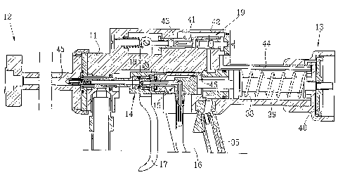
Fig. 1 shows a section through a spray gun according to the
invention in closed, passive position.
Fig. 2 shows in bigger scale a section through the
intermediate portion of the spray gun, with the valves in
open, active position.
Fig. 2a is a partial enlargement of the encircled portion 2a
from Fig. 2.
Fig. 2b is a partial enlargement of the encircled portion 2b
from Fig. 2.
Description of embodiment
The spray gun according to the invention consists of a
central housing 11, which at its forward part is equipped
with a spraying nozzle 12 and at its rearmost portion with
a servo mechanism 13. The central housing 11

CA 02288908 2006-06-27
2a
incorporates two valves 14 and 15, the inner one 15 of which
is provided within the other, outer valve 14. The housing
also incorporates a handle 16 and in front of this a trigger
17 in the form of a two-armed lever, which is pivotable
about a shaft 18. In the upper part of the housing is also
provided a valve arrangement 19 for controlling the servo
mechanism 13.
The outer valve 14, which is axially displaceable in the
housing 11 consists of a sleeve 20, which passes over into

CA 02288908 1999-10-22
WO 98/47625 PCT/SE98/00704
3
a coaxial tube 21, which extends into the spraying nozzle
12. A protective bushing 22 is thread over the tube 21, and
the forward tapering end 23 of which cooperates with a valve
seat 24 in the housing 11. At the front end of the tube is
provided a non-return valve 25, which opens at a pressure
inside the tube. The protective bushing 22 is surrounded by
an annular channel 30, which communicates with a supply
conduit 31 for a first medium, e.g. polyester. At the
transition between the tube 21 and the sleeve 20 is provided
a valve seat 26 in the latter, which cooperates with the end
surface of the valve body 27 of the inner valve 15. This is
constituted by a tube 28, the forward end of which is
closed, but provided with lateral openings 29, which
communicate with a second annular channel 32, which can be
brought in communication with the interior channel 33 of the
tube 21, when the valve body 27 is displaced in a direction
away from its seat 26 and the opening of the channel 33 is
exposed.
The inner valve 15, which is axially displaceable in the
sleeve 20 of the outer valve 14, passes over with its
tubular valve body 28 into a bush 34, which is guided inside
the sleeve 20. The inner channel 36 of the tube 28 opens at
this bushing, and a supply conduit 37 for a second medium,
e.g. a hardening agent is connected to this channel. A
piston rod 39 of a piston 40, forming part of the servo
mechanism 13 and being subjected to load by a pressure
spring 38 is also attached to the bushing 34.
A conduit 35 for pressurized air is also connectable to the
housing 11, and which supplies pressurized air to a valve
stem 41 equipped with two valve bodies 42 and 43, one of
which always closes against a valve seat, whereas the other
one is open. The position of the valve stem is controlled by
means of the trigger 17. When the trigger is acted upon, the

CA 02288908 1999-10-22
WO 98/47625 PCT/SE98/00704
4
valve body 42 opens the passage to an air conduit 44, which
leads the pressurized air to the forward side of the piston
40. The piston rod 39 thereby will be subjected to a tensile
force acting against the action of the spring 38. The
tensile force is transferred to the bushing 34, whereby the
entire valve package consisting of the outer and the inner
valves 14, 15 is displaced against a stop 46, such as shown
in Fig. 2 and 2a. In this stage the two valves 14, 15 form
an interconnected unit, due to the fact that the second
medium contained in the annular slot 32 and the channel 36
is under pressure. In this position the passage beyond the
valve seat 24 is opened, thus that the first medium can flow
from the supply conduit 31 to the connecting channel 45 of
the spray nozzle 12. This channel is designed as a mixing
chamber or mixing channel equipped with not shown, for
instance screw-shaped, mixing members.
At continued supply of pressurized air to the piston 40 the
passage beyond the valve seat 26 will be opened, thus that
the second medium can flow from the annular slot 32 to the
inner channel 33 of the tube 21 and further to the non-
return valve 25, which is thereby opened. Thereby the second
medium will reach the mixing chamber 45 and an intimate
mixing of the two media can take place.
As the outlet opening for the second medium at 25 is
situated somewhat in front of the outlet openings at 24 for
the first medium and the first medium always is discharged
first, there will not be any contamination at these outlet
openings 24. The cleaning then can be limited to wiping off
the non-return valve 25, after the spraying nozzle 12 has
been screwed off.
r ~ . 1

CA 02288908 1999-10-22
WO 98/47625 PCT/SE98/00704
List over reference numerals
11 housing
12 spraying nozzle
5 13 servo mechanism
14 outer valve
inner valve
16 handle
17 trigger/lever
10 18 shaft
19 valve arrangement
sleeve
21 tube
22 protective bushing
15 23 tapering end
24 valve seat
non-return valve
26 valve seat
27 valve body
20 28 tube
29 opening
lst annular channel
31 supply conduit
32 2nd annular channel
25 33 inner channel
34 bushing
conduit for pressurized air
36 inner channel
37 supply conduit
30 38 pressure spring
39 piston rod
piston
41 valve stem
42 valve body
35 43 valve body
44 air conduit
connecting channel/mixing chamber
46 stop

Representative Drawing
A single figure which represents the drawing illustrating the invention.
Administrative Status

2024-08-01:As part of the Next Generation Patents (NGP) transition, the Canadian Patents Database (CPD) now contains a more detailed Event History, which replicates the Event Log of our new back-office solution.

Please note that "Inactive:" events refers to events no longer in use in our new back-office solution.

For a clearer understanding of the status of the application/patent presented on this page, the site Disclaimer , as well as the definitions for Patent , Event History , Maintenance Fee  and Payment History  should be consulted.

Event History

Description Date
Inactive: Expired (new Act pat) 2018-04-17
Maintenance Request Received 2013-03-20
Inactive: Office letter 2012-02-10
Inactive: Reversal of will be deemed expired status 2012-02-10
Letter Sent 2011-04-18
Grant by Issuance 2007-11-13
Inactive: Cover page published 2007-11-12
Pre-grant 2007-08-17
Inactive: Final fee received 2007-08-17
Letter Sent 2007-03-13
Notice of Allowance is Issued 2007-03-13
Inactive: IPC removed 2007-03-06
Inactive: Approved for allowance (AFA) 2007-02-19
Inactive: Office letter 2007-01-26
Inactive: Corrective payment - s.78.6 Act 2007-01-18
Amendment Received - Voluntary Amendment 2006-09-13
Inactive: S.30(2) Rules - Examiner requisition 2006-09-05
Amendment Received - Voluntary Amendment 2006-06-27
Inactive: IPC from MCD 2006-03-12
Inactive: S.30(2) Rules - Examiner requisition 2006-01-03
Letter Sent 2005-09-26
Reinstatement Requirements Deemed Compliant for All Abandonment Reasons 2005-09-02
Letter Sent 2005-05-19
Deemed Abandoned - Failure to Respond to Maintenance Fee Notice 2005-04-18
Letter Sent 2002-11-06
Request for Examination Received 2002-10-04
Request for Examination Requirements Determined Compliant 2002-10-04
All Requirements for Examination Determined Compliant 2002-10-04
Inactive: Entity size changed 2002-04-18
Letter Sent 2000-03-08
Inactive: Single transfer 2000-02-18
Inactive: Cover page published 2000-01-04
Inactive: First IPC assigned 1999-12-23
Inactive: Courtesy letter - Evidence 1999-12-14
Inactive: Notice - National entry - No RFE 1999-12-07
Application Received - PCT 1999-12-06
Application Published (Open to Public Inspection) 1998-10-29

Abandonment History

Abandonment Date Reason Reinstatement Date
2005-04-18

Maintenance Fee

The last payment was received on 2007-04-10

Note : If the full payment has not been received on or before the date indicated, a further fee may be required which may be one of the following

  • the reinstatement fee;
  • the late payment fee; or
  • additional fee to reverse deemed expiry.

Patent fees are adjusted on the 1st of January every year. The amounts above are the current amounts if received by December 31 of the current year.
Please refer to the CIPO Patent Fees web page to see all current fee amounts.

Owners on Record

Note: Records showing the ownership history in alphabetical order.

Current Owners on Record
APLICATOR SYSTEM AB
Past Owners on Record
PEDER JONSSON
Past Owners that do not appear in the "Owners on Record" listing will appear in other documentation within the application.
Documents

To view selected files, please enter reCAPTCHA code :


To view images, click a link in the Document Description column (Temporarily unavailable). To download the documents, select one or more checkboxes in the first column and then click the "Download Selected in PDF format (Zip Archive)" or the "Download Selected as Single PDF" button.

List of published and non-published patent-specific documents on the CPD .

If you have any difficulty accessing content, you can call the Client Service Centre at 1-866-997-1936 or send them an e-mail at CIPO Client Service Centre.

({010=All Documents, 020=As Filed, 030=As Open to Public Inspection, 040=At Issuance, 050=Examination, 060=Incoming Correspondence, 070=Miscellaneous, 080=Outgoing Correspondence, 090=Payment})


Document
Description 
Date
(yyyy-mm-dd) 
Number of pages   Size of Image (KB) 
Representative drawing 2000-01-03 1 19
Abstract 1999-10-21 1 60
Description 1999-10-21 5 186
Claims 1999-10-21 2 61
Drawings 1999-10-21 4 151
Description 2006-06-26 6 199
Claims 2006-06-26 2 55
Claims 2006-09-12 2 54
Representative drawing 2006-10-19 1 25
Reminder of maintenance fee due 1999-12-19 1 111
Notice of National Entry 1999-12-06 1 193
Courtesy - Certificate of registration (related document(s)) 2000-03-07 1 113
Acknowledgement of Request for Examination 2002-11-05 1 176
Courtesy - Abandonment Letter (Maintenance Fee) 2005-06-12 1 175
Notice of Reinstatement 2005-09-25 1 164
Commissioner's Notice - Application Found Allowable 2007-03-12 1 162
Correspondence 1999-12-08 1 14
PCT 1999-10-21 8 301
Correspondence 2005-05-18 1 20
Fees 2005-04-11 1 23
Correspondence 2005-10-13 1 42
Fees 2005-10-26 1 44
Fees 2005-04-11 2 64
Correspondence 2007-01-25 1 13
Correspondence 2007-08-16 1 29
Fees 2008-03-30 1 33
Fees 2009-03-26 1 29
Fees 2010-03-29 1 33
Correspondence 2012-02-09 1 14
Fees 2011-04-03 1 31
Fees 2012-03-22 1 38
Fees 2013-03-19 1 32