Note: Descriptions are shown in the official language in which they were submitted.
. CA 02288921 2005-O1-14
1
A method of tamping a track
The invention relates to a method of tamping a track with a track
position measuring system having a measuring chord formed by a light beam,
the measuring chord.being defined by two measuring reference points which
are formed respectively by a tracer element designed to roll on the track
by means of flanged rollers, wherein the first measuring reference point is
positioned in front of a tamping machine, in the working direction, and the
second
measuring reference point is positioned between on-track undercarriages of the
machine.
Known from US 3 545 384 is a tamping machine having a machine
frame supported on on-track undercarriages with which a tamping- as well as
a lifting and lining unit are associated for carrying out tamping operations.
For
controlling the track position correction, a track position measuring system
is
used, having a measuring chord formed by a light beam. Said measuring chord
is defined by a first measuring reference point, preceding the machine in the
working direction, and a trailing second measuring reference point positioned
in the region of the track lifting unit. The measuring chord is oriented in a
predetermined direction parallel to the desired position of the track. A
receiver
forming the second measuring reference point comprises two light-sensitive
cells which are spaced from one another vertically by a certain distance. The
light beam forming the measuring chord thus causes two kinds of impulses
which can be used for controlling the track lifting and tamping units.
According to AT 314 580, it is also known to control track lining tools
directly by a laser transmitter connected thereto. Toward that end, a bundle
of
laser beams is directed from the transmitter to a fixed point located next to
the
track. The~~ack can thus be displaced with the aid of the track lining tools
until
the beam bundle emanating from the transmitter is aligned with an indicator
mark located on the fixed point.
According to EP 0 401 260 B1, a measuring chord positioned in front of
a surveying wagon is known which is defined by a measuring reference point
known by coordinates and a further measuring reference point positioned at the
center of a receiver device made up of a multitude of photo cells. In
connection
CA 02288921 2005-O1-14
2
with a distance measuring device, it is possible to accurately determine the
deviation of the second measuring reference point from the desired position.
A further measuring reference system, preceding a track position correcting
machine and having a measuring chord formed by two reference points, is known
from AT 328 490.
The object of the present invention is to provide a method of the specified
kind with which it is possible in an optimal way to bring, in particular,
short track
sections into a desired position.
According to the invention, this object is achieved with a method of the
specified kind which is comprising the following steps: forming the measuring
chord
connecting the first and second measuring reference points A,B; advancing the
machine in a first forward movement to the first measuring reference point A
which
remains stationary, while relative displacements of the second measuring
reference
point B are registered with regard to the measuring chord maintained
stationary
during the advance of the machine, thus forming an actual position curve;
computing a desired position curve of the track from the actual position
curve, thus
forming correction values; and returning the machine to the initial departing
point
and subsequently again advancing the machine in a second forward movement to
the first measuring reference point A which remains stationary, while, on the
basis
of the measuring chord maintained stationary and leading through the first
measuring reference point A, the track is lifted into a desired position
according to
the determined correction values and tamped.
This method makes it possible with a minimum of conversion operations to
very quickly detect the actual track position and to accurately carry out
correction
operations. The track displacements can be precisely detected in an
advantageous
way during the operational forward movement by registering the relative
displacement between the two measuring reference points, so that after the
position correction has been accomplished, the track position accurately
corresponds to the calculated desired values. A particular advantage of this
direct
controlling of the second measuring reference point and thereby also of the
track
lifting and lining unit may be seen in the fact that the track position
correction can
be carried out in the track section to be corrected without, in a time-
consuming
manner, forming a ramp to the adjoining, unchanged track section.
CA 02288921 2005-O1-14
3
According to the invention, this object is achieved with a method of tamping
a track with a track position measuring system having a measuring chord formed
by
a light beam, the measuring chord being defined by first and second measuring
reference points A,B which are formed respectively by a tracer element
designed to
roll on the track by means of flanged rollers, wherein the first measuring
reference
point A is positioned in front of a tamping machine, in a working direction,
and the
second measuring reference point B is positioned between on-track
undercarriages
of the machine, comprising the following steps: forming the measuring chord
connecting the first and second measuring reference points A,B, advancing the
machine in a first forward movement to the first measuring reference point A
which
remains stationary, and, in doing so, registering relative displacements of
the first
measuring reference point A with regard to the measuring chord maintained
stationary relative to the machine during the advance of the machine, thus
forming
an actual position curve, computing a desired position curve of the track from
the
actual position curve, thus forming correction values, and returning the
machine to
the departing point of the first advance and subsequently advancing the
machine in
a second forward movement to the measuring reference point A which remains
stationary, while, on the basis of the measuring chord, maintained stationary
with
regard to the machine and leading through the second measuring reference point
B, and the deviations of the measuring chord from the first measuring
reference
point A, the track is lifted into a desired position according to the
determined
correction values and tamped.
Additional advantages of the invention become apparent from the drawings.
The invention will be described in more detail below with reference to an
embodiment represented in the drawing in which
Fig. 1 shows a side view of a tamping machine for tamping a track,
having a track position measuring system,
Fig. 2 shows a schematized top view of the tamping machine
having a track position measuring system formed by a transmitter
and receiver, and
CA 02288921 2005-O1-14
3a
Fig. 3 shows an actual position curve of a track section, detected by
the track position measuring system.
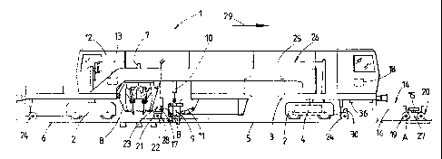
A tamping machine 1, shown in Fig. 1, comprises a machine frame 3
supported on on-track undercarriages 2 and is designed to travel by means of a
motive drive 4 on a track 6 composed of sleepers and rails 5. Provided for
performing track tamping operations are tamping units 8, vertically adjustable
by
drives 7, as well as a lifting and lining unit 9 having lifting and lining
drives 10,11. A
central control device 13 is located in a driver's or operator's cab 12.
For detecting track position deficiencies, a track position measuring system
14 is provided which is essentially composed of a laser transmitter 15, a
measuring
chord 16 formed by a light beam, a receiver 17, and a controlling and
computing
unit 18. The measuring chord 16 is established by a measuring reference point
A,
formed at the exit point of the light beam, and a second measuring reference
point
B determined by the contact with the receiver 17 designed as a line camera 23.
The transmitter 15 of the track position measuring system 14 is located on a
satellite wagon 20, mobile independently of the tamping machine 1, which has
flanged rollers 19 and forms a first tracer element 27. The receiver 17 is
connected
to a measuring axle 22, positioned between the tamping unit 8 and
CA 02288921 1999-11-04
4
lifting and lining unit 9, which is mobile on the track 6 by means of flanged
rollers 21 and forms a second tracer element 28. The measuring axle 22 also
forms part of a further reference system 26 constituted by measuring axles 24
and a steel chord 25. The measuring axle 24, located forwardly with regard to
the working direction (arrow 29), of the reference system 26 is connected to
an
odometer 30.
It can be seen in Fig. 2 that the optical measuring chord 16, established
by the two measuring reference points A and B, is positioned laterally
adjacent
to the machine. For this purpose, the line camera 23 of the rearward tracer
element 28 is designed to extend laterally beyond a machine outline 31 in the
transverse direction of the machine.
Shown in Fig. 3 is an actual position curve 32 of the track 6, formed
from a multitude of individual measurements. The measurements consist of
registering the relative displacement 33 between the measuring reference
point B, situated in the region of the lifting and lining unit 9, and the
stationary
measuring reference point A. The relative displacement values are thus defined
in each case by the distance between the stationary measuring chord 16 and
the respective measuring point on the line camera 23 guided along the track 6.
The correction values 34 added in each case to the relative displacements 33
yield a desired position curve 35 of the track 6. Parallel to the measurement,
the distance s travelled by the machine 1 is registered by the odometer 30.
The implementation of the method according to the invention will be
described in more detail below.
After passing over the track section to be corrected, the satellite wagon
20 is released from a fixing mechanism 36 of the machine 1 and set onto the
track 6. Thereafter, the machine 1 travels backwards opposite to the working
direction represented by the arrow 29, until the machine 1 is standing on a
track section which is not to be corrected anymore. The tracer element 28
immediately preceding the tamping unit 8 is set down into the track 6 and
pressed against a rail 5 serving as a reference line. Subsequently, the laser
transmitter 15 is directed at, preferably, the center of the receiver 17 and
fixed
CA 02288921 1999-11-04
in its position relative to the satellite wagon 20. During the measuring run,
now starting, of the machine 1 in the direction towards the satellite wagon
20,
relative displacements 33 (Fig. 3) according to the track position faults take
place between the stationary measuring chord 16 and the line camera 23
following the course of the rails. Said relative displacements 33 are stored
in the controlling and computing unit 18 in connection with a distance
measurement by the odometer 30.
While the tamping machine 1 is moved back again to the beginning of
the track section to be corrected, a desired position curve 35 is developed
and
the corresponding correction values 34 are determined by the controlling and
computing unit 18 based on the surveyed actual position curve 32. During the
operational forward movement now beginning, immediately before the start of
the track position correction, the measuring chord 16 is directed
automatically
at that measuring point on the line camera 23 which was registered during the
measuring run and used for establishing the actual position curve 32. To carry
out the track position correction, the track 6 is now displaced by the lifting
and
lining unit 9 with regard to the vertical and lateral position until that
measuring
point in the two-dimensional line camera 23 is aimed at which produces the
calculated correction value 34 with reference to the actual position.
It goes without saying that the method according to the invention,
while yielding the same result, may be modified inasfar as the laser
transmitter
may be connected to the measuring axle 22, and the receiver 17 to the
satellite wagon 20. In this case, the line camera 23 would be stationary while
the measuring chord 16 is moved relative to the track 6 or the machine 1 in
accordance with the course of the track.