Note: Descriptions are shown in the official language in which they were submitted.
CA 02288924 1999-11-04
DEGRADED ELECTRONIC THROTTLE OPERATION METHOD AND SYSTEM
Background of the Invention
The present invention relates to torque motors. Motors of this type typically
provide angular
displacement or movement of a rotor by an amount proportional to the
characteristics of an electrical
signal applied to the windings of the motor. For example, angular movement can
be proportional to
the voltage applied to the motor winding.
Torque motors have found widespread application in various control systems. In
these systems it
is desirable to rotate a shaft to a specific position or to apply a specified
amount of torque to a shaft in
response to an electrical control signal. In one particular system, it has
been desirable to utilize a
torque motor to control the position of a throttle plate within an internal
combustion engine. One such
system is described in co-pending Canadian application Ser. No. 2,272,022,
filed May 11, 1999,
assigned to the assignee of this disclosure is directed to breaking ice within
a throttle assembly after a
period of non-use. Another such system controls the position of the air inlet
throttle valve by an
electrical signal during engine operation.
With regard to controlling throttle plate position in an operating engine,
older systems were
directly mechanically controlled by user movement of a throttle linkage
attached to the throttle valve.
On the other hand, electrical throttle valve control is especially desirable
in certain motor vehicle
applications such as to provide cruise control andlor to override the user
input to the throttle position
control mechanism in response to extreme driving conditions or emergency
situations. For example,
where an anti-lock brake system, traction control system or yaw rate control
system is employed on the
vehicle, it is desired under certain conditions to have the electronic control
system determine the
throttle position rather than the operator.
A drawback exists however with respect to electrically controlled throttle
systems. Namely, if
the vehicle electrical system fails, or if electrical power to the throttle
motor is interrupted, the
electrical signal controlling the vehicle throttle position vanishes causing
the throttle valve to Afloat.
It has been appreciated in the art that a floating throttle may open further
thus accelerating a vehicle
unexpectedly or dangerously. In recognition of this danger, throttle control
systems typically include
springs to close a throttle valve in the absence of opening torque provided by
the throttle controller
CA 02288924 1999-11-04
. . . .
mechanism or motor. However, this spring closure feature results in sharply
diminished airflow to the
vehicle motor causing the vehicle to slow and eventually to stop, perhaps in
traffic, again potentially
placing the occupants and nearby vehicles in danger.
The present invention contemplates a new, safer electronic throttle and method
of use, which
overcomes the above referenced problems and others.
Brief Summary of the Invention
In accordance with the present invention, a method of ensuring continued
airflow to an engine
controlled by an electronic throttle system during a time of electrical power
loss is provided. The
method includes the steps of positioning a throttle plate within an air/fuel
intake manifold such that the
throttle plate is movable between an open position allowing airflow through
the manifold and a closed
position substantially blocking airflow. Also included is the application of a
first torque to the throttle
plate to urge the throttle plate toward the open position and application of a
second torque urging the
throttle plate toward the closed position. The first and second torques
counteract each other so that the
throttle plate remains at a position between the open and closed positions to
allow airflow through the
manifold.
In accordance with another aspect of the present invention, the first torque
is provided by the
electromagnetic properties of a torque motor and the second torque is provided
by a return spring.
In accordance with a more limited aspect of the present invention, the method
further includes
determining a reluctance torque curve by plotting a specific reluctance torque
value for a range of
positions of the throttle plate. Then the throttle plate is aligned such that
the reluctance torque value for
a desired position cancels the closing bias at the desired position. At this
desired position, the throttle
plate is sufficiently open to provide airflow through the manifold to the
engine.
In accordance with an additional aspect of the present invention, a method of
configuring an
electronic throttle assembly to operate in a degraded mode without electrical
power is provided. An
opening torque is applied to a throttle plate tending to urge the throttle
plate to an open position,
allowing airflow through a manifold. Simultaneously, a closing torque is
applied to the throttle plate
2
CA 02288924 1999-11-04
tending to urge the throttle plate to a closed position. The simultaneous,
opposite torque applications
leave the throttle plate in a neutral, slightly open position.
In accordance with another aspect of the present invention, opening torque is
applied by steps
including connecting the throttle plate to a rotating portion of an
electromagnetic torque motor. The
torque motor defines a plurality of reluctance torque values based on the
position of the rotating
portion. The throttle plate is placed in an offset position allowing the
reluctance torque to provide the
opening torque.
In accordance with another aspect of the present invention, an electronic
throttle includes a
throttle plate movably disposed within an airlfuel intake manifold. The
throttle plate travels between a
first position substantially blocking airflow and a second position
substantially permitting airflow. A
torque motor defines a variable first torque which urges the throttle plate
toward the second position
when no current passes through the windings of the motor. Oppositely, a means
for providing a second
torque that tends to urge the throttle plate toward the first position is also
included. A shaft is also
included in operative connection between the torque motor and the throttle
plate. The shaft is angularly
aligned such that the throttle plate rests in an equilibrium position between
the first and second
positions.
In accordance with a more limited aspect of the present invention, the
variable first torque is
produced by electromagnetic properties of the torque motor.
In accordance with a more limited aspect of the present invention, the means
for providing the second
torque is a return spring.
One advantage of the present invention resides in the provision of a method
which ensures
continued airflow to an engine during periods of power failure.
Another advantage of the present invention is the provision of a method which
configures an electronic
throttle assembly in a way to allow degraded operation in the absence of
electrical power.
Other benefits and advantages of the present invention will become apparent to
those skilled in the art
upon a reading and understanding of the detailed description of the preferred
embodiments.
3
CA 02288924 1999-11-04
Brief Description of the Drawings
The invention may take form in certain parts and arrangements of parts, and in
certain steps and
arrangements of steps, preferred embodiments of which are illustrated herein.
The drawings are only
for purposes of illustrating preferred embodiments and are not to be construed
as limiting the invention.
FIGURE 1 is a simplified diagrammatic illustration of a motor vehicle internal
combustion engine air
intake system and associated electronic throttle control system;
FIGURE 2 is a graphical representation of torque variance measured against
throttle position.
Detailed Description of the Invention
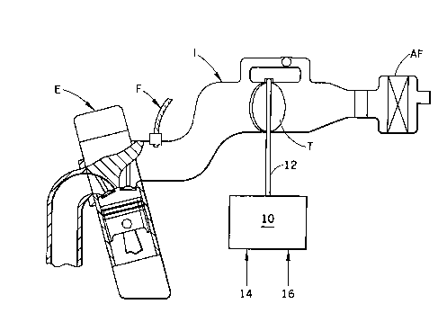
Referring to FIGURE 1 a simplified internal combustion engine includes an
air/fuel intake
manifold I. Air enters the manifold I through an air filter AF. The flow of
air into and through the
manifold I is controlled by a throttle plate valve T. The throttle plate valve
T selectively blocks air
flow in one position or is rotated a varying amount allowing a select airflow
to pass into the internal
combustion engine E. A fuel injector F selectively injects gasoline or other
fuel into the air stream for
combustion in the engine E.
The angular position of the throttle plate T is controlled by the torque motor
10. More
particularly, the output shaft 12 of the motor 10 is connected with the
throttle plate T so that the plate
rotates at the urging of the motor 10. The torque motor 10 receives electrical
power 14 and command
signals 16. Those of ordinary skill in the art will recognize that if power 14
is lost to the torque motor
10, operator desired positioning of throttle plate T is lost. Thus, an
operator of a vehicle will be unable
to control the speed of the internal combustion engine E.
Referring now to FIGURE 2, the graph 20 depicts torque on the vertical axis 22
and is measured
in ounce-inches (oz-in). Throttle position on the horizontal axis 24 is
depicted in terms of degrees of
rotation of the throttle plate valve T. If a torque motor winding carries no
current, the torque vs.
4
CA 02288924 1999-11-04
position curve MTO is basically zero except at the extremities. This is called
Areluctance torqueQ and
is due to a large rate of change of stored energy as the pole tips of the
torque motor begin to interact
with the magnet transition from North to South. On the other hand, at maximum
torque motor winding
current, the torque vs. position curve MTmax shows nearly uniform torque at
all positions except the
extremes.
Also shown in FIGURE 2, is a return spring torque curve 30. The negative
reflected return
spring curve 32 shows a point of intersection with the reluctance torque curve
MTO. This point of
intersection is the Alimp homeQ position 34. The return effect will be
enhanced by throttle shaft offset
if used. Hence, ignoring friction, those of ordinary skill in the art will
recognize that the throttle T will
remain at the limp home position 34 if there is no current in the coils.
Airflow may slightly urge the
throttle T toward the throttle closed position 36, normally a mechanical stop.
The net effect is a self regulating throttle valve T. If the engine speed
increases, airflow through
the manifold I increases and throttle offset will pull the position of the
throttle T back, decreasing
airflow, slowing the engine. If engine speed decreases, reduced airflow
through manifold I will allow
the throttle T to open under the force of the reluctance torque MTO, thus
increasing engine speed.
Those skilled in the art will recognize that the present development defines a
self regulating system for
controlling the position of the throttle plate valve T when electrical power
to the motor 10 is lost.
With continuing reference to Figure 2, position 38 defines a fully open
position for the throttle
valve T. Accordingly, the throttle valve is movable between the first and
second positions 36, 38 which
are each defined by mechanical stops to prevent movement of the throttle plate
T therepast.
Normal operation with positive current generates additional torque MTmax over
the reluctance
torque MTO. Hence, the throttle plate T mechanism will open. Or, in other
words, the throttle plate
will move along the throttle position axis 24 away from the closed position 36
toward the fully open
position 38. The effective motor torque on the throttle plate can be seen as
the difference between the
positive motor torque (e.g. MTmax) and the reflected return spring curve 32.
CA 02288924 1999-11-04
Idle speed below the limp home position 34 is achieved by passing negative
current through the
windings of the torque motor 10 to pull the throttle T toward the closed
position 36 overcoming the
reluctance torque MTO Ahill.Q Gradual increase in the magnitude of the
negative current will
generate a torque that will pull the throttle plate mechanism T against the
stop 36.
Curve 40 depicts a torque applied to the throttle plate T in response to a
negative current passed
through the windings of the motor. As is evident, the negative current is
required to completely close
the throttle T overcoming reluctance torque MTO. In the absence of negative
electrical current to
completely close the throttle T, the operator will have to engage other means
of stopping the vehicle
when it is safe to stop, for instance, a wheel brake assembly, or a change of
transmission gearing.
While the invention has been described with respect to the illustrated
embodiments, it will be
understood that the invention is capable of modification and variation and is
limited only by the
following claims.
6