Language selection

Search

Patent 2289035 Summary

Third-party information liability

Some of the information on this Web page has been provided by external sources. The Government of Canada is not responsible for the accuracy, reliability or currency of the information supplied by external sources. Users wishing to rely upon this information should consult directly with the source of the information. Content provided by external sources is not subject to official languages, privacy and accessibility requirements.

Claims and Abstract availability

Any discrepancies in the text and image of the Claims and Abstract are due to differing posting times. Text of the Claims and Abstract are posted:

  • At the time the application is open to public inspection;
  • At the time of issue of the patent (grant).
(12) Patent: (11) CA 2289035
(54) English Title: LIQUID LEVEL SENSOR FOR USE IN A HOT, PRESSURIZED LIQUID
(54) French Title: JAUGE DE NIVEAU POUR LIQUIDES CHAUDS SOUS PRESSION
Status: Deemed expired
Bibliographic Data
(51) International Patent Classification (IPC):
  • G01F 23/00 (2006.01)
  • G01F 23/292 (2006.01)
(72) Inventors :
  • ROMATZICK, DAVID H. (United States of America)
(73) Owners :
  • CASCO PRODUCTS CORPORATION (United States of America)
(71) Applicants :
  • CASCO PRODUCTS CORPORATION (United States of America)
(74) Agent: MOFFAT & CO.
(74) Associate agent:
(45) Issued: 2007-01-09
(86) PCT Filing Date: 1998-03-25
(87) Open to Public Inspection: 1998-11-19
Examination requested: 2002-12-11
Availability of licence: N/A
(25) Language of filing: English

Patent Cooperation Treaty (PCT): Yes
(86) PCT Filing Number: PCT/US1998/005958
(87) International Publication Number: WO1998/052014
(85) National Entry: 1999-10-29

(30) Application Priority Data:
Application No. Country/Territory Date
08/856,907 United States of America 1997-05-15

Abstracts

English Abstract


In a preferred embodiment, a liquid level sensor (10) for use
in a hot, pressurized liquid (14), including: an outer housing (20)
suitable for immersion in liquid (14); an inner housing (22) disposed
within outer housing (20) and containing therein electronic/electrical
components (70); detection apparatus (74) disposed within outer
housing (20) and inner housing (22) to detect the level of liquid (14);
a space defined between outer housing (20) and inner housing (22);
and means (98) to permit liquid (14) which migrates through a wall
of outer housing (20) into the space and which is vaporized therein to
pass to the ambient surroundings, so as to preclude migration of the
liquid through a wall of inner housing (22).


French Abstract

L'invention porte sur une jauge de niveau (10) pour liquides (14) chauds sous pression comportant une enveloppe extérieure (20) conçue pour être plongée dans le liquide (14), une enveloppe intérieure (22) placée dans l'enveloppe extérieure (20) et contenant des composants (70) électroniques et électriques, un appareil de détection (74) placé dans l'enveloppe extérieure (20) et l'enveloppe intérieure (22) et servant à mesurer le niveau de liquide (14), un espace compris entre le logement extérieur (20) et le logement intérieur (22), et des moyens (98) permettant au liquide (14), migrant à travers une paroi de l'enveloppe extérieure (20) vers l'espace intermédiaire où il se vaporise, de rejoindre l'atmosphère environnante afin d'empêcher la migration du liquide à travers une paroi de l'enveloppe intérieure (22).

Claims

Note: Claims are shown in the official language in which they were submitted.


-7-

Claims

1. A liquid level sensor for use in a hot,
pressurized liquid, comprising:
(a) an outer housing suitable for immersion in
said liquid;
(b) an inner housing disposed within said outer
housing and containing therein
electronic/electrical components;
(c) detection means disposed within said outer
housing and said inner housing to detect level
of said liquid;
(d) a space defined between said outer housing and
said inner housing; and
(e) means to permit said liquid which migrates
through a wall of said outer housing into said
space and which is vaporized therein to pass
to the ambient surroundings, so as to preclude
migration of said liquid through a wall of
said inner housing.

2. A liquid level sensor, as defined in Claim 1,
wherein: said space and an interior of said inner
housing are at atmospheric pressure.

3. A liquid level sensor, as defined in Claim 1,
wherein: said outer housing and said inner housing are
generally cylindrical and coaxial and said detection
means includes a prism disposed at lower ends of said
outer and inner housings and protruding into said
liquid.

4. A liquid level sensor, as defined in Claim 1,
wherein: said outer housing is constructed of
polypropylene and said inner housing is constructed of
polycarbonate.


-8-

5. A liquid level sensor, as defined in Claim 1,
wherein: said means to permit comprises at least one
passageway defined between said outer housing and said
inner housing.

Description

Note: Descriptions are shown in the official language in which they were submitted.


CA 02289035 1999-10-29
WO 98/52014 PCTNS98/05958
-1-
Description
Liquid Level Sensor for Use in a Hot, Pressurized Liquid
Technical Field
The present invention relates to liquid level
sensors generally and, more particularly, but not by way
of limitation, to a novel liquid level sensor especially
useful for sensing the level of hot, pressurized water
or aqueous solutions.
Background Art
Liquid level sensors are widely used for sensing
the levels of a variety of liquids.
One type of liquid level sensor optically senses
the level of a liquid by using a light emitting diode
(LED) to provide a light beam to a prism disposed at the
bottom or in the side of a hollow plastic tube inserted
in the liquid. If the level of the liquid is at or
above the level of the prism, the light beam passes
through the prism into the liquid. If, however, the
level of the liquid is below the level of the prism, the
light beam is reflected from the prism to a
photodetector. Electronic circuitry disposed within the
tube and connected to the LED and the photodetector
provides an output signal indicating whether or not the
liquid level is at or above the level of the sensor and
the output signal is used to provide such indication
and/or or to activate an alarm, for example. Additional
pairs of LEDs and photodetectors may be provided at
other levels in the plastic tube to sense other levels
of the liquid in the same manner. Examples of liquid
level sensors of the optical type described above and
details of their operation are generally disclosed in US
Patents Nos. 4,840,137, issued June 20, 1989, and
SUBSTITUTE SHEET (RULE 26)

CA 02289035 2006-04-11
-2-
5,279,157, issued Jan. 18, 1994.
It has been found that, when a liquid level sensor of
the type described above is used with a pressurized aqueous
solution, such as the coolant used in vehicle engines, for
example, water tends to migrate through the plastic tube
and interfere with the electronic/electrical components in
the plastic tube.
Accordingly, it is a principal object of the present
invention to provide a liquid level sensor for use with
water or aqueous solutions that prevents water from
contacting electronic circuitry therein.
It is a further object of the invention to provide
such a liquid level sensor that can be used to sense the
level of hot, pressurized water or aqueous solutions.
It is an additional object of the invention to provide
such a liquid level sensor that is easily and economically
constructed.
Other objects of the present invention, as well as
particular features, elements, and advantages thereof, will
be elucidated in, or be apparent from, the following
description and the accompanying drawing figures.
DISCLOSURE OF INVENTION
The present invention achieves the above objects,
among others, by providing, in a preferred embodiment, a
liquid level sensor for use in a hot, pressurized liquid,
comprising: an outer housing suitable for immersion in said
liquid; an inner housing disposed within said outer housing
and containing therein electronic/electrical components;
detection means disposed within said outer housing and said
inner housing to detect level of said liquid; a space
defined between said outer housing and said inner housing;
and means to permit said liquid which migrates through a
wall of said outer housing into said space and which is

CA 02289035 1999-10-29
WO 98/52014 PCT/US98iu~958
-3-
vaporized therein to pass to the ambient surroundings,
so as to preclude migration of said liquid through a
wall of said inner housing.
Brief Description of the Drawincts
Understanding of the present invention and the
various aspects thereof will be facilitated by reference
to the accompanying drawing figure, submitted for
purposes of illustration only and not intended to define
the scope of the invention, on which:
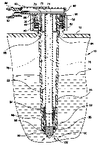
The sole drawing figure is an enlarged, side
elevational view, partially in cross-section, of a
liquid level sensor constructed according to the present
invention and mounted in a container of a liquid.
Best Mode for Carrying Out the Invention
Reference should now be made to the drawing figure
on which there is illustrated a liquid level sensor,
constructed according to the present invention, and
generally indicated by the reference numeral 10. Level
sensor is shown mounted on a container 12 which contains
a pool of liquid 14 which may be assumed to be hot,
pressurized coolant in a vehicle engine (not shown),
such liquid being for example, ethylene glycol/water
coolant.
Level sensor 10 includes an outer, generally
cylindrical, vertical, plastic housing 20 which is
slightly tapered from its upper end to its lower end.
Outer housing 20 is constructed of a suitable material
compatible with the coolant liquid, such as
polypropylene. A generally cylindrical, vertical,
plastic inner housing 22 is disposed coaxially
internally of outer housing 20 and extends substantially
the length thereof. Inner housing 22 is constructed of
a suitable material, such as polycarbonate.
SUBSTITUTE SHEET (RULE 26)

CA 02289035 1999-10-29
WO 98/52014 PCT/US98/05958
-4-
The upper end of housing 20 terminates in an
outwardly facing, annular flange 30 which has an
upwardly facing, cylindrical flange 32 formed near the
edge thereof. An internally threaded bonnet 40,
constructed of a suitable thermoplastic material,
engages the upper surface of flange 30 and a threaded
nozzle 42 on container 12 to removably mount level
sensor 10 to the container. An annular rubber seal 44
is disposed between the lower surface of flange 30 and
the top of nozzle 40.
A generally cylindrical prism 50, preferably
constructed of polysulfone or polyetherimide, extends
from the lower end of outer housing 20 and has an upper
cylindrical portion 52 having the same diameter as inner
housing 22. The lower end of inner housing 22 abuts the
upper end of cylindrical portion 52 and is joined
thereto by a cylindrical rubber sleeve 54 extending over
the cylindrical portion and a section of the lower end
of the inner housing. An outwardly facing, annular
flange 56 formed around the lower end of cylindrical
portion 52 rests on an inwardly facing annular flange 58
formed around the inner periphery of the lower end of
outer housing 20. A circular rubber seal 60 is
frictionaily disposed between the peripheral surface of
prism 50 and the inner surface of outer housing 20 to
seal the interior of the outer housing against the
ingress of liquid 14.
Internally disposed at the upper end of inner
housing 22 is a circuit board 70 on which are disposed a
light emitting diode (LED) 72 and a photodetector 74.
LED 72 is arranged so as to provide an incident light
beam 76 to prism 50 and photodetector 74 is arranged so
as to receive a reflected light beam 78 from the prism.
Circuit board 70 is operatively connected to LED 72,
photodetector 74, and contact pins, as at 82, in an
electrical connector 84 formed at one end of the upper
portion of inner housing 22.
SUBSTITUTE SHEET (RULE 26)

CA 02289035 2006-04-11
-5-
A cup shaped member 88 is formed as part of inner
housing 22 and extends around the upper end thereof
defining, in part, an upper housing 90 of which electrical
connector 84 is a part and in which mounting plate 70 is
disposed. Upper housing 90 is closed by a dust cap 92. The
inner surface of outer housing 20 and a portion of the
outer surface of cup shaped member 88 are separated by
spacing ribs, as at 94, to provide a series of vertical
channels, as at 96, for communication between the annular
space defined between outer and inner housings 20 and 22
and the ambient surroundings through an annular space 98.
In operation, and is described in detail in the
above-referenced patents, LED 72 provides incident light
beam 76 to the inner surface of prism 50. As described
above, if the level of liquid 14 is at or above the level
of prism 50 (as is shown on the figure), then light beam
will exit the outer surface 100 of prism 50, as at 102. If,
however, the level of liquid 14 were below the level of
prism 50, incident light beam will be reflected internally
from outer surface 100 and reflected light beam 78 will be
detected by photodetector 74. In either case, circuitry
(not shown) on circuit board 70 will provide an appropriate
output signal through electrical connector 84, the signal
in the latter case indicating a low level condition.
As indicated above, the annular space defined between
outer and inner housings 20 and 22 is at atmospheric
pressure and level sensor 10 is constructed such that the
interior of inner housing is not hermetically sealed so
that that space, also, is at atmospheric pressure.
Therefore, there is no differential pressure across the
wall of the inner housing. Now, if any of the water in hot,
pressurized coolant liquid 14 migrates through the wall of
outer housing 20 into the annular space defined between
outer and inner housings 20 and 22, there will be no
pressure

CA 02289035 2006-04-11
-6-
potential to drive the water through the wall of inner
housing 22 into the interior of the inner housing
containing circuit board 70. Since the temperature of
pressurized liquid 14 is above the atmospheric boiling
point of water, the interior of level sensor 10 will also
be above the atmospheric boiling point of water, and any
water in the annular space defined between outer and inner
housings 20 and 22 will evaporate and will pass upwardly
through vertical channels 94 and out of level sensor 10
through annular space 98 into the ambient surroundings,
thus precluding the possibility of water contacting circuit
board 70.
It will thus be seen that the objects set forth above,
among those elucidated in, or made apparent from, the
preceding description, are efficiently attained and, since
certain changes may be made in the above construction
without departing from the scope of the invention, it is
intended that all matter contained in the above description
or shown on the accompanying drawing figures shall be
interpreted as illustrative only and not in a limiting
sense.
It is also to be understood that the following claims
are intended to cover all of the generic and specific
features of the invention herein described and all
statements of the scope of the invention which, as a matter
of language, might be said to fall therebetween.

Representative Drawing
A single figure which represents the drawing illustrating the invention.
Administrative Status

For a clearer understanding of the status of the application/patent presented on this page, the site Disclaimer , as well as the definitions for Patent , Administrative Status , Maintenance Fee  and Payment History  should be consulted.

Administrative Status

Title Date
Forecasted Issue Date 2007-01-09
(86) PCT Filing Date 1998-03-25
(87) PCT Publication Date 1998-11-19
(85) National Entry 1999-10-29
Examination Requested 2002-12-11
(45) Issued 2007-01-09
Deemed Expired 2016-03-29

Abandonment History

There is no abandonment history.

Payment History

Fee Type Anniversary Year Due Date Amount Paid Paid Date
Application Fee $300.00 1999-10-29
Registration of a document - section 124 $100.00 1999-12-20
Maintenance Fee - Application - New Act 2 2000-03-27 $100.00 2000-02-28
Maintenance Fee - Application - New Act 3 2001-03-26 $100.00 2001-01-03
Maintenance Fee - Application - New Act 4 2002-03-25 $100.00 2002-01-11
Request for Examination $400.00 2002-12-11
Maintenance Fee - Application - New Act 5 2003-03-25 $150.00 2002-12-30
Maintenance Fee - Application - New Act 6 2004-03-25 $200.00 2004-01-07
Maintenance Fee - Application - New Act 7 2005-03-25 $200.00 2005-02-21
Maintenance Fee - Application - New Act 8 2006-03-27 $200.00 2005-12-29
Final Fee $300.00 2006-10-05
Maintenance Fee - Patent - New Act 9 2007-03-26 $200.00 2007-01-05
Maintenance Fee - Patent - New Act 10 2008-03-25 $250.00 2007-12-21
Maintenance Fee - Patent - New Act 11 2009-03-25 $250.00 2008-11-18
Maintenance Fee - Patent - New Act 12 2010-03-25 $250.00 2009-12-17
Maintenance Fee - Patent - New Act 13 2011-03-25 $250.00 2011-02-23
Maintenance Fee - Patent - New Act 14 2012-03-26 $250.00 2012-02-14
Maintenance Fee - Patent - New Act 15 2013-03-25 $450.00 2013-03-01
Maintenance Fee - Patent - New Act 16 2014-03-25 $450.00 2014-02-27
Owners on Record

Note: Records showing the ownership history in alphabetical order.

Current Owners on Record
CASCO PRODUCTS CORPORATION
Past Owners on Record
ROMATZICK, DAVID H.
Past Owners that do not appear in the "Owners on Record" listing will appear in other documentation within the application.
Documents

To view selected files, please enter reCAPTCHA code :


To view images, click a link in the Document Description column. To download the documents, select one or more checkboxes in the first column and then click the "Download Selected in PDF format (Zip Archive)" or the "Download Selected as Single PDF" button.

List of published and non-published patent-specific documents on the CPD .

If you have any difficulty accessing content, you can call the Client Service Centre at 1-866-997-1936 or send them an e-mail at CIPO Client Service Centre.


Document
Description 
Date
(yyyy-mm-dd) 
Number of pages   Size of Image (KB) 
Representative Drawing 2000-01-06 1 15
Claims 1999-10-29 2 44
Drawings 1999-10-29 1 38
Abstract 1999-10-29 1 57
Description 1999-10-29 6 276
Cover Page 2000-01-06 1 57
Description 2006-04-11 6 260
Representative Drawing 2006-08-23 1 14
Cover Page 2006-12-06 2 52
Fees 2004-01-07 1 38
Correspondence 1999-12-10 1 2
Assignment 1999-10-29 3 94
PCT 1999-10-29 6 236
Assignment 1999-12-20 5 208
Fees 2002-12-30 1 37
Prosecution-Amendment 2002-12-11 1 41
Fees 2007-01-05 1 60
Fees 2001-01-03 1 36
Fees 2002-01-11 1 37
Fees 2000-02-28 1 34
Correspondence 2005-01-25 1 18
Fees 2005-02-21 1 36
Prosecution-Amendment 2006-01-19 2 38
Fees 2005-12-29 1 36
Prosecution-Amendment 2006-04-11 5 167
Correspondence 2006-10-05 1 54