Note: Descriptions are shown in the official language in which they were submitted.
CA 02289389 1999-11-12
PATENT
Attorney Docket No.: 05516/027001
Smith Concept No. 97-ST25
INSERTS FOR EARTH-BORING BITS
Field of the Invention
This invention relates to earth-boring bits with superhard material enhanced
inserts
for drilling blast holes, oil and gas wells, and the like.
Background of the Invention
Earth-boring bits, such as roller cone rock bits and percussion rock bits, may
be
employed for drilling oil wells through rock formations, or for drilling blast
holes for
blasting in mines and construction projects. Earth-boring bits also are
referred to as drill
bits. During operation, a drill bit is connected to the end of a drill string
and rotated to drill
through the earth. One variety of drill bits, the roller cone rock bits, have
a plurality of
wear-resistant inserts secured in rotatable cones attached to a bit body. The
inserts usually
have a substantially cylindrical body portion which is adapted to fit in a
cylindrical hole in
the roller cone and a top portion which protrudes from the roller cone for
contacting an
earthen formation.
When a roller cone rock bit is used to drill a borehole, it is important that
the
diameter or "gage" of the borehole be maintained at a desired value. The first
row of
inserts from the center of the rock bit on each roller cone that cuts to a
full gage borehole
typically is referred to as the "gage row." This row of inserts generally is
subjected to the
greatest wear, as it both reams the borehole wall and cuts the corner of the
borehole. As
the gage row inserts wear, the diameter of the borehole being drilled may
decrease below
the original gage diameter of the rock bit. When the bit is worn out and
removed, the
diameter of the bottom portion of the hole may be less than the gage diameter,
or "under-
gage." When the next bit is run in the hole, it is required to ream that
bottom portion of the
borehole to bring it to the full gage diameter. This not only takes
substantial time but also
adds to the wear on the gage row inserts of the next bit. This additional wear
on the gage
row inserts may result in an increased length of under-gage borehole as the
bit wears out.
1
CA 02289389 1999-11-12
In addition to gage row inserts, a conventional bit typically includes a
number of
inner row inserts located on a roller cone and disposed radially inward from
the gage row.
These inner row inserts are sized and configured for cutting the bottom of the
borehole.
Sometimes, a conventional bit also may include a plurality of secondary
inserts located
between the gage row inserts. These inserts, referred to as "nestled gage
inserts," typically
cut the full gage of the borehole and also assist the gage inserts in cutting
the borehole
corner. Moreover, a conventional rock bit may further include a row of heel
inserts located
on the frustoconical surface of a roller cone. The heel row inserts generally
scrape and
ream the side wall of a borehole as the roller cone rotates about its
rotational axis.
The performance of a rock bit is measured, in part, by total drilling footage
and rate
of penetration. As the inserts on a rock bit wear, the rate of penetration
typically
decreases. When the inserts have been substantially worn out, it is no longer
economical
to continue drilling that bit, and the bit is replaced. The amount of time
required to make a
"round trip" for replacing a bit, i.e., pull all of the drill string out of
the borehole, replace
the worn-out bit, and reassemble the drill string into the borehole,
essentially represents
time lost from actual drilling. This time can become a significant portion of
the total time
for completing a well. Therefore, it is highly desirable to design and
manufacture inserts
that would increase the rate of penetration and total drilling footage of a
rock bit. In
particular, there have been numerous attempts to reduce wear on the gage row
inserts to
increase the length of a borehole drilled to full gage.
Two kinds of wear-resistant inserts typically are used in a rock bit -
tungsten
carbide inserts and polycrystalline diamond ("PCD") enhanced inserts. Tungsten
carbide
inserts are formed of cemented tungsten carbide. A typical composition for
cemented
tungsten carbide is tungsten carbide particles dispersed in a cobalt binder
matrix. The
PCD enhanced insert, an improvement over the tungsten carbide insert,
typically includes a
cemented tungsten carbide body as a substrate and a layer of polycrystalline
diamond
directly bonded to the tungsten carbide substrate on the top portion of the
insert.
Although the polycrystalline diamond layer is extremely hard and wear-
resistant, a
PCD enhanced insert still may fail during normal operation. The typical
failure mode is
cracking of the polycrystalline diamond layer due to high contact stress, lack
of toughness,
and insufficient fatigue strength. A crack in the polycrystalline diamond
layer during
2
CA 02289389 1999-11-12
drilling may cause the polycrystalline diamond layer to spall or delaminate.
Furthermore,
a crack in the polycrystalline diamond layer may propagate through the
cemented tungsten
carbide body of the insert and cause more massive failure of the insert. On
the other hand,
wear of the polycrystalline diamond layer can be a failure mode leading to
failure of an
insert, particularly in percussion rock bits.
For the foregoing reasons, there exists a need for PCD enhanced inserts that
possess not only high hardness but also desired toughness and other properties
to drill
through rock formations without premature breakage or delamination of the
polycrystalline
diamond layer.
Summary of the Invention
The invention meets the aforementioned need by the following aspects. In one
aspect, the invention relates to an insert for an earth-boring bit. The insert
comprises a
body portion adapted for attachment to the earth-boring bit and a non-
cylindrical top
portion for contacting an earthen formation to be drilled. The top portion
includes
superhard material having a first region and a second region, and the
superhard material in
the first region has a composition different from the superhard material in
the second
region. In some embodiments, the top portion includes a substrate and a layer
of the
superhard material provided over at least a portion of the substrate. The
superhard material
in the first region may have a higher toughness (or lower hardness) than the
superhard
material in the second region. Moreover, the first region may lie in the
primary surface of
the insert. In some embodiments, the hardness of the superhard material in the
first region
is at least 500 Vickers lower than the hardness of the superhard material in
the second
region. Superhard material may include diamond and cubic boron nitride.
In another aspect, the invention relates to a polycrystalline diamond enhanced
insert
for an earth-boring bit. The insert comprises a substantially cylindrical body
portion
adapted for attachment to the earth-boring bit and a non-cylindrical top
portion for
contacting an earthen formation to be drilled. The body portion is formed of
cemented
tungsten carbide, and the top portion has a primary surface and secondary
surface. The top
portion includes a cemented tungsten carbide substrate and a polycrystalline
diamond layer
over at least a portion of the substrate. The polycrystalline diamond in the
primary surface
3
CA 02289389 1999-11-12
has a lower wear resistance than the polycrystalline diamond in the secondary
surface of
the top portion.
In still another aspect, the invention relates to a rock bit. The rock bit
comprises a
bit body, a roller cone rotatably mounted on the bit body, and an insert with
a body portion
S and a top portion. The body portion is secured in the roller cone, and the
top portion
includes superhard material with a first region and a second region. The
superhard
material in the first region has a composition different from the superhard
material in the
second region. The top portion of the insert may be cylindrical or non-
cylindrical. The
insert may be a gage row insert, an inner row insert, a nestled gage row
insert, heel row
inserts, etc. In some embodiments, the first region lies in the gage contact
face of the
insert, and the superhard material in the first region is less wear resistant
than the superhard
material in the second region.
In yet another aspect, the invention relates to a rock bit. The rock bit
comprises a
bit body, a roller cone rotatably mounted on the bit body, and a plurality of
inserts with a
substantially cylindrical body and a non-cylindrical top portion. The body
portion is
secured in the roller cone, and the top portion includes a substrate and a
polycrystalline
diamond layer over at least a portion of the substrate. The top portion has a
primary
surface and secondary surface. The polycrystalline diamond in the primary
surface has a
higher toughness or lower wear resistance than the polycrystalline diamond in
the
secondary surface of the top portion.
In yet still another aspect, the invention relates to an earth-boring bit. The
earth-
boring bit comprises a retention body and an insert with a body portion and a
non-
cylindrical top portion. The body portion is secured in the retention body,
and the top
portion includes superhard material with a first region and a second region.
The superhard
material in the first region has a composition different from the superhard
material in the
second region.
In one aspect, the invention relates to a rock bit. The rock bit comprises a
bit body,
and a roller cone rotatably mounted on the bit body. The roller cone has
cutting elements
integrally formed thereon, and the cutting elements include superhard material
with a first
region and a second region. The superhard material in the first region has a
composition
different from the superhard material in the second region.
4
CA 02289389 1999-11-12
In another aspect, the invention relates to a method of manufacturing an
insert. The
method comprises (a) providing an insert with a body portion and a non-
cylindrical top
portion; and (b) providing superhard material over at least a portion of the
top portion of
the insert. The superhard material has a first region and a second region. The
superhard
material in the first region has a composition different from the superhard
material in the
second region. Preferably, the hardness of the superhard material in the first
region is at
least 500 Vickers lower than the hardness of the superhard material in the
second region.
In some embodiments, a layer of the superhard material is formed under a high
pressure
and temperature condition for sintering the superhard material. Furthermore, a
high-shear
compaction tape including a composition for the superhard material may be used
for
forming the layer of superhard material. A composite construction material
including a
composition for the superhard material also may be used for forming the layer
of superhard
material.
In still another aspect, the invention relates to a method of manufacturing a
rock
bit. The method comprises (a) providing a bit body; (b) rotatably mounting a
roller cone to
the bit body; and (c) attaching an insert to the roller cone. The insert has a
body portion
secured in the roller cone and a top portion. The top portion includes
superhard material
with a first region and a second region. The superhard material in the first
region has a
composition different from the superhard material in the second region.
In yet another aspect, the invention relates to a method of manufacturing an
earth-
boring bit. The method comprises (a) providing a retention body; and (b)
attaching an
insert to the retention body. The insert has a body portion and a non-
cylindrical top
portion. The body portion is secured in the retention body, and the top
portion includes
superhard material with a first region and a second region. The superhard
material in the
first region has a composition different from the superhard material in the
second region.
In yet still another aspect, the invention relates to a method of
manufacturing a rock
bit. The method comprises (a) providing a roller cone having cutting elements
integrally
formed thereon; (b) providing superhard material over at least a portion of
the surface of
the cutting elements; and (c) rotatably mounting the integrated roller cone to
a leg of a bit
body. The superhard material has a first region and a second region, and the
superhard
5
CA 02289389 1999-11-12
material in the first region has a composition different from the superhard
material in the
second region.
Description of the Drawings
Figure lA is a perspective view of a prior art PCD enhanced insert with a
chisel
shaped top portion.
Figure 1B is a cross-sectional view of the prior art PCD enhanced insert of
Figure
1 A taken along the line 1 B-1 B.
Figure 1C is a perspective view of a prior art PCD enhanced insert with a semi-
round top portion.
Figure 2 is an overlay of all three roller cones of a rock bit and their
respective
inserts rotated into the same plane.
Figure 3A is a perspective view of an improved PCD enhanced insert according
to
one embodiment of the invention.
1 S Figure 3B is a top view of the improved PCD enhanced insert of Figure 3A.
Figure 4A is a perspective view of one roller cone of a rock bit in a borehole
as
viewed from the top of the borehole down to the bit while drilling.
Figure 4B is an enlarged view of the insert 50 of Figure 4A showing the
location of
the leading edge, trailing edge, and outer lateral face.
Figure 4C is a perspective view of another roller cone of a rock bit in a
borehole as
viewed from the top of the borehole down to the bit while drilling.
Figure SA is a perspective view of an insert showing various faces of the top
portion of the insert.
Figure SB is a top view of the insert of Figure SA.
Figure 6A is a perspective view of another embodiment of an improved PCD
enhanced insert with an inclined chisel-shaped top portion according to the
invention.
Figure 6B is a top view of the improved PCD enhanced insert of Figure 6A.
Figure 6C is a side view of the improved PCD enhanced insert of Figure 6A.
Figure 7 is a perspective view of an improved insert in accordance with an
embodiment of the invention.
6
CA 02289389 1999-11-12
Figure 8 is perspective view of an improved insert in accordance with another
embodiment of the invention.
Figure 9 is a perspective view of still another embodiment of an improved PCD
enhanced insert having a semi-round top portion according to the invention.
Figure 10 is a perspective view of yet another embodiment of an improved PCD
relieved gage insert having an asymmetrical top portion according to the
invention.
Figure 11 is a partially sectioned exploded view of components used to
fabricate an
improved PCD enhanced insert according to an embodiment of the invention.
Figure 12 is a top view of a preformed high-shear compaction tape used in
Figure
11.
Figure 13A is a perspective view of one embodiment of the composite
construction
material used in embodiments of the invention.
Figure 13B is a perspective view of another embodiment of the composite
construction material used in embodiments of the invention.
Figure 14 is a fragmentary longitudinal cross-sectional view of a percussion
bit in
accordance with an embodiment of the invention.
Figure 15 is a perspective view of a rock bit manufactured in accordance with
an
embodiment of the invention.
Detailed Description of the Preferred Embodiments
Embodiments of the invention provide improved inserts for an earth-boring bit
that
include a body portion adapted for attachment to the earth-boring bit and a
non-cylindrical
top portion for contacting an earthen formation to be drilled. The top portion
includes
superhard material with two or more regions. The superhard material in a first
region has a
composition different from the superhard material in a second region.
Embodiments of the invention are based, in part, on the realization that
different regions of
an insert encounter different loading conditions and consequently, different
stresses, i.e.,
tensile, compressive, fatigue, etc. It is believed that wear of a
polycrystalline diamond
layer on a typical PCD enhanced insert is not the dominate mode of failure of
such an
insert. Rather, a PCD enhanced insert fails due to chipping and breakage of
the
polycrystalline diamond layer and the tungsten carbide substrate. A
homogeneous
7
CA 02289389 1999-11-12
polycrystalline diamond layer on an insert (as has been practiced in prior
art) is not
optimized for handling non-uniform loading and wear conditions. Therefore, a
polycrystalline diamond layer with multiple regions having different wear
resistance and
toughness characteristics on a wear-resistant PCD enhanced insert may be
better suited to
handle the different loading and wear conditions.
Figure lA shows a perspective view of a typical prior art PCD enhanced insert,
and
Figure 1B is a cross-sectional view of the prior art PCD enhanced insert. An
insert 10
includes a cylindrical body portion 11 and a top portion 12. A substantially
homogeneous
layer of polycrystalline diamond 18 typically is overlaid on all of the faces
of the top
portion 12. The polycrystalline diamond layer 18 is bonded to a tungsten
carbide insert 17
which serves as a substrate. Optionally, there may be one or more transition
layers 19
between the polycrystalline diamond layer 18 and the substrate 17 that reduce
the residual
stress that develops because of the thermal expansion differences between the
polycrystalline diamond and tungsten carbide materials.
Because the polycrystalline diamond layer 18 has a substantially homogeneous
composition throughout the surface of the top portion 12 of the prior art
insert 10, the wear
resistance of the polycrystalline diamond layer throughout the entire surface
of the top
portion 12 is uniform. However, during use, different regions of the top
portion 12
experience dissimilar loading, wear, and impact forces, and therefore, have
different
requirements for strength, wear resistance, and toughness, which are not met
by the prior
art insert 10.
For example, when the insert 10 of Figure 1C (which shows an insert with a
semi-
round top portion) is used in a percussion rock bit , it experiences heaviest
wear in certain
regions of the insert. In this instance, it is desirable to provide a more
wear-resistant
polycrystalline diamond layer in this region than in other regions of the
insert.
On the other hand, when the insert 10 of Figure lA is used in a roller cone
bit, no
significant wear occurs in the polycrystalline diamond layer. Instead,
chipping and
breakage of the polycrystalline diamond layer may occur. This is because some
regions of
the insert, e.g., the primary surface (illustrated in Figure 2), experience
substantially higher
impact and/or loading forces than other regions of the insert. The impact
force can initiate
cracks on the surface of the polycrystalline diamond layer where the insert
contacts the
8
CA 02289389 1999-11-12
earthen formation. Localized chipping of the polycrystalline diamond layer may
occur
when the crack length reaches a critical level. After the formation of
localized chipping of
the polycrystalline diamond layer, several events may occur, including (1)
crack
propagation into the tungsten carbide substrate; (2) spalling and/or peeling
of the
S polycrystalline diamond layer; and (3) creation of a wear flat on the
tungsten carbide
substrate. The formation of a wear flat, although less frequent, is due to
loss of the
polycrystalline diamond layer surrounding the wear flat and the wear of
exposed carbide
substrate. As the polycrystalline diamond layer chips, spalls, and peels off,
substantial loss
of the wear-resistant material on the insert may occur, which typically leads
to eventual
destruction of the insert and loss of cutting efficiency. These stages of
events leading to
failure of an insert are typical for inner row inserts, gage inserts, nestled
gage inserts, and
heel row inserts.
To overcome the problems of chipping and breakage of the polycrystalline
diamond layer, it is desirable to incorporate a less wear-resistant
polycrystalline diamond
IS layer in the area or region of an insert where it is subjected to higher
impact forces and/or
fatigue loading. By providing a less wear resistance polycrystalline diamond
layer in this
area, preferential wear is promoted in this area. As the polycrystalline
diamond in this area
is worn away in a more controlled fashion, chipping and breakage of the
polycrystalline
diamond layer may be minimized. It should be noted that a tougher
polycrystalline
diamond layer also may have the same or similar effects. This is because a
tougher
polycrystalline diamond layer generally is more resistant to impact forces.
Because different areas of the top portion of an insert are subjected to
different
loading, wear, fatigue, impact forces, and associated stresses, the
polycrystalline diamond
layer on the top portion should be made up of two or more regions. Each region
should be
provided with a polycrystalline diamond layer with wear resistance, strength,
and
toughness commensurate with the wear and loading conditions for that
particular region or
area, instead of a uniform layer of polycrystalline diamond.
Generally, polycrystalline diamond possesses mechanical properties similar to
a
ceramic material, i.e., the hardness or wear resistance of a polycrystalline
diamond layer
generally is inversely related to its toughness or fracture strength. As the
hardness or wear
resistance increases, the toughness decreases, and vice versa. However, there
may be
9
CA 02289389 1999-11-12
exceptions to this inverse relationship. There are at least two ways to
minimize chipping
and breakage of a polycrystalline diamond layer: use of a less wear resistant
polycrystalline diamond layer and provision of a tougher polycrystalline
diamond layer.
In embodiments of the invention, a polycrystalline diamond layer with higher
toughness or lower wear resistance is provided in the region of an insert
where it is
subjected to substantially higher impact forces and/or fatigue loading to
minimize localized
chipping of the polycrystalline diamond on the insert. In the meantime, a
polycrystalline
diamond layer with higher hardness or wear resistance is provided to the
regions of the
insert where hardness and wear resistance is required. PCD enhanced inserts
with such
configuration should be capable of reducing the formation and propagation of
localized
chipping of a polycrystalline diamond layer, thus lengthening the life of the
inserts. It has
been determined that a difference of hardness of at least 500 Vickers between
the two
regions may be sufficient to help alleviate chipping andlor breakage of the
polycrystalline
diamond layer.
1 S Inserts with such configuration may have additional beneficial properties.
For
example, when a less wear-resistant polycrystalline diamond layer is placed in
the primary
surface of an insert, the polycrystalline diamond layer in this primary
surface preferentially
will wear more rapidly. Once the lower wear-resistant diamond wears away,
exposing the
substrate material below it, edges of the adjacent polycrystalline diamond
layer (that have a
higher wear resistance) are exposed. Such a polycrystalline diamond cutting
edge can
provide a shearing cutting action which is more efficient when cutting a
borehole wall.
The formation of the polycrystalline diamond cutting edge in a shearing action
may help
increase the rate of penetration of a rock bit incorporating these types of
improved inserts.
The improved inserts according to embodiments of the invention may include two
or more regions of different superhard material compositions. Furthermore, any
two
regions need not be adjacent to each other; nor need they form a contiguous
layer. The top
portion may include a substrate over which the superhard material is provided.
In this
case, the substrate of the top portion may be partially exposed, so long as
two or more
regions of the carbide substrate are covered by superhard material with
different
compositions. Also, a connecting region between two or more regions of
different
CA 02289389 1999-11-12
superhard material composition may be formed of a gradient material
composition to avoid
drastic discontinuities that could occur due to substantially different
compositions.
It should be understood that a superhard material composition may differ in a
variety of ways. For example, it may differ by chemical components, weight
percentage of
S the chemical components, and physical characteristics of each component
(such as particle
size and particle size distribution). Furthermore, two superhard material
compositions also
are considered different if they have different wear resistance, toughness, or
other
mechanical properties. For example, two regions could have the same material
composition but be processed differently to result in different mechanical
properties.
As mentioned above, an insert includes a body portion adapted for attachment
to an
earth-boring bit and a top portion for contacting an earthen formation. The
top portion
typically is integral with the body portion, although it need not be. When the
body portion
is secured in a roller cone, the top portion protrudes from the roller cone.
The top portion
generally refers to the part of the insert that protrudes from the roller
cone.
In some embodiments, a top portion includes a substrate and a layer of
superhard
material over at least a portion of the substrate. The substrate may be formed
of carbide,
nitride, silicide, and other suitable materials. Preferably, cemented tungsten
carbide in a
cobalt matrix is used as the material for the substrate. Generally, the body
portion is
formed of the same material as the substrate of the top portion. However, it
is entirely
feasible to manufacture inserts with the body portion and the substrate being
formed of
different materials.
The top portion may take any shapes, cylindrical or non-cylindrical.
Preferably, the
entire top portion has a non-cylindrical shape, e.g., ballistic, conical, semi-
round,
symmetrical, asymmetrical, chisel-shaped, inclined chisel-shaped, etc. The
term "non-
cylindrical" refers to any three-dimensional shape that is not a cylinder. A
cylinder is a
solid or hollow body having its figure traced out when a rectangle rotates
360° using one
of its sides as the axis of rotation. Although the entire top portion is non-
cylindrical, it still
may include a part that is cylindrical.
Each top portion has an outer surface (i.e., the entire surface of the top
portion) for
contacting a formation which comprises a primary surface and a secondary
surface. The
term "primary surface" herein refers to the area or surface that substantially
contacts a
11
CA 02289389 1999-11-12
borehole or substantially parallels the sidewall of a borehole. The contact
can occur at the
sidewalk the bottom, or a portion of the corner of a borehole. The secondary
surface is the
remainder of the outer surface of a top portion.
Figure 2 illustrates the meaning of "primary surface." It is a sectional view
of an
overlay of all three roller cones of a tri-cone rock bit and their respective
rows of inserts
rotated into the same plane. Referring to Figure 2, the roller cones
collectively indicated as
24 include a heel row insert 22, a gage row insert 20, and a plurality of
inner row inserts
21. The gage row insert 20 contacts the wall surface 23 of the borehole at the
borehole
corner. The point or area of contact 25, on the insert 20, between the wall
surface 23 and
the gage row insert 20 generally is referred to as the primary surface for
gage row inserts.
This surface sometimes is referred to as the "gage contact area" or the "wear
face."
Similarly, there also exists an area of contact between a heel row insert and
the borehole
sidewall. Inner row inserts 21 generally contacts the formation at the crest
area (indicated
by the boldface) 27 and the outer corner 28. Therefore, these areas are
referred to as the
1 S primary surface.
Sometimes, it is desirable to provide an additional row of gage cutting
inserts on a
roller cone, known as "nestled gage inserts" or "secondary gage insets". The
nestled or
secondary gage inserts are located between the conventional gage inserts 20 on
the gage
row of a roller cone. These additional inserts generally help cut and maintain
the borehole
to its intended diameter. They also may cut the corner of the borehole. The
location of the
primary surface on a nestled gage insert is similar to that on a gage insert.
One embodiment of the improved insert is illustrated as a gage row insert in
Figures 3A and 3B. Refernng to Figure 3A, an improved insert 30 includes a
body portion
31 and a top portion 32. The body portion 31 generally is secured in a roller
cone and may
take a variety of geometrical shapes. In a preferred embodiment, the body
portion 31 is
substantially cylindrical.
Referring to Figures 3A and 3B, the chisel-shaped top portion 32 includes a
leading
face 36, a trailing face 34, a leading edge 37, a trailing edge 38, a crest
33, and an outer
lateral face 35 (which is optional). The outer lateral face sometimes is
referred to as "wear
face." Figure 3B is a top view of the top portion 32. It should be noted that
the surface of
the top portion 32 is provided with a layer of superhard material which is
divided into at
12
CA 02289389 1999-11-12
least two regions 35 and 39. The region 35 includes a superhard material that
has a
different composition from the superhard material in region 39. In this
embodiment, the
region 35 lies in the primary surface of the insert, and it also coincides
with the entire outer
lateral face. However, in other embodiments, only a portion of the outer
lateral face is
S provided with a layer of superhard material different from that of another
region.
The leading edge and face are defined, respectively, as the area or face of
the top
portion of an insert on a rock bit that first contacts an earthen formation as
the bit rotates.
The trailing edge and face are respectively the area or face of the top
portion opposite the
leading edge. The trailing edge contacts the formation after the leading edge
as the roller
cone rotates. The terms "leading" and "trailing" are used herein to refer to
these areas
respectively, regardless of whether the areas so referred to are planar,
contoured, or include
an edge.
Figure 4A and Figure 4B illustrate the concept of "leading" and "trailing."
Figure 4A is a perspective view of a roller cone of a rock bit in a borehole
as viewed from
1 S the top of the borehole down to the bit while drilling. A roller cone 40
includes heel row
inserts 44, off gage row inserts 50, gage row inserts 41, and inner row
inserts 43. It should
be noted that Figure 4A and Figure 4B illustrate a TrucutTM bit design of
Smith
International, Inc., in which the off gage inserts 50 are used in conjunction
with the gage
row inserts 41 located on the gage row 47. Furthermore, the off gage inserts
have a chisel-
shaped top portion, whereas the gage inserts have a semi-round top portion
(although any
other shapes also are acceptable). In this design, no nestled gage inserts are
present.
However, the gage inserts 41 would be considered as nestled gage inserts if
the off gage
inserts SO were moved to the gage row 47.
It should be understood that variations with respect to the location and
insert
geometry may exist for different bit designs. However, the same "leading" and
"trailing"
concepts apply to any conventional bit design. One such example of a
conventional bit
design is illustrated in Figure 4C. In this design, there are no off gage
inserts, and the gage
inserts have a chisel-shaped top portion.
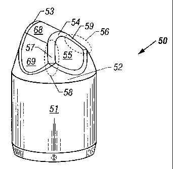
Referring to Figure 4B, the insert 50 includes a leading edge 59, a leading
face 67,
a trailing edge 57, a trailing face 69, an outer lateral face 55, a crest 68,
and an outer
edge 54. As the rock bit (not shown) rotates clockwise in a borehole, the
roller cone 40
13
CA 02289389 1999-11-12
rotates counterclockwise. As such, the leading edge 59 and the leading face 67
contact the
formation first, and the trailing edge 57 and the trailing face 69 contact the
formation later.
It should be understood that the location of the respective faces or edges on
the same insert
will be reversed if the roller cone rotates in the opposite direction.
S For a known direction of bit rotation, the respective locations of the
leading and trailing
edges or faces may be readily determined. Figure SA and Figure SB illustrate
the relative
location of a leading face 67, a leading edge 59, a trailing face 69, a
trailing edge 57, an
outer lateral face 55, a crest 68, and an outer edge 54. In this embodiment,
portions of the
leading face 67, the outer lateral face 55, the leading edge 59, and the outer
edge 54
collectively make up a leading transition 56. Similarly, portions of the
trailing face 69, the
outer lateral face 55, the trailing edge 57, and the outer edge 54
collectively make a trailing
transition 58. It should be understood that, in embodiments of the invention,
any one of
the aforementioned areas or faces is considered as a separate region and thus
may be
provided with a superhard material different from another region.
1 S Although it is desirable to provide a tougher or less wear-resistant
polycrystalline
diamond layer in the primary surface (i.e., gage contact area) of a gage row
insert, it is by
no means the only desirable region where the tougher or less wear-resistant
polycrystalline
diamond layer may be provided. Other regions may include, entirely or portions
thereof,
the leading face 36, the trailing face 34, the crest 33, the leading edge 37,
and the trailing
edge 38 of Figure 2A. Moreover, the leading transition region 56 and the
trailing transition
region 58 of Figure SA also may be provided with a layer of tougher or less
wear-resistant
material.
In some embodiments, the primary surface of an insert is provided with a
polycrystalline diamond layer that has a higher toughness or lower wear
resistance than the
polycrystalline diamond layer in the secondary surface of the insert. The
primary surface
also could be separated into two or more regions of different polycrystalline
diamond
compositions to optimize bit performance. In other embodiments, the primary
surface of
an insert is provided with a polycrystalline diamond layer that has a lower
toughness or
higher wear resistance than the polycrystalline diamond layer in the secondary
surface of
the insert.
14
CA 02289389 2004-10-26
77680-1
It should be recognized that inserts with various shapes and surface finishes
may be
employed in embodiments of the invention. For example, inserts with a
contoured surface
are especially suitable. Such inserts are disclosed in U.S. Patent No.
5,322,138. Inclined
chisel inserts are disclosed in U.S. Patent No. 5,172,777. Furthermore, shaped
inserts with
its outer lateral face relieved or canted also are
suitable. Such shaped inserts are disclosed in
U.S. Patent No. 6,059,054, entitled "Non-Symmetrical
Stress-Resistant Rotary Drill Bit Cutter Element".
Figure 6A is a perspective view of an improved inclined chisel insert with a
layer
of polycrystalline diamond. The improved insert 60 includes a cylindrical body
portion 61
and a top portion 62. The body portion 61 may fiuther include a chamfered base
65. The
top portion 62 includes a polycrystalline diamond layer over a carbide
substrate (not
shown). The polycrystalline diamond layer has at least two distinct areas:
region 64 and
region 66. The polycrystalline diamond in the region 66 is tougher or less
wear-resistant
than the polycrystalline diamond in the region 64. Preferably, the region 66
coincides with
the primary surface of the insert. However, it is entirely acceptable to place
a layer of
tougher or less wear-resistant polycrystalline diamond in other areas of the
top portion 62.
Figure 6B is a top view of the improved insert 60, and Figure 6C is a side
view of the
insert.
Figure 7 shows a perspective view of an improved insert in accordance with
another embodiment of the invention. The improved insert 70 includes a top
portion 71
having a conical shape and a body portion 72. The top portion 71 includes a
polycrystalline diamond layer 73 at the crest of the top portion and a
polycrystalline
diamond layer 74 covering the remainder of the top portion. The wear
resistance or
toughness of the layer 73 differs from that of the layer 74. In some
applications, the layer
73 is tougher or less wear-resistant than the layer 74. In other applications,
the layer 73 is
more wear-resistant or less tough than the layer 74. Such improved inserts are
especially
suitable as inner row inserts.
Figure 8 shows a perspective view of an improved insert in accordance with
still
another embodiment of the invention. The improved insert 80 includes a top
portion 81
having a flat top and a body portion 82. The top portion 81 includes a first
polycrystalline
CA 02289389 1999-11-12
diamond region 83 and a second polycrystalline diamond region 84. It further
includes a
portion of the carbide substrate beneath the polycrystalline diamond regions
that supports
the polycrystalline diamond regions. The wear resistance or toughness of the
region 83
differs from that of the region 84. In some applications, the region 83 is
tougher or less
wear-resistant than the region 84. In other applications, the region 83 is
more wear-
resistant or less tough than the region 84. Such improved inserts are
especially suitable as
heel row inserts.
In addition to the above geometrical shapes, the top portion of an improved
insert
may be any other configurations, such as semi-round as illustrated in Figure 9
and
asymmetrical as illustrated in Figure 10. The construction of the improved
insert shown in
Figure 9 and Figure 10 is similar to the inclined chisel insert of Figures 6A-
6C described
above.
Suitable superhard material includes diamond, cubic boron nitride, and other
materials with comparable wear resistance. Generally, wear resistance is
proportional to
hardness. However, some materials may have high hardness but modest wear
resistance.
This kind of materials also may be used in embodiments of the invention. It is
recognized
that the hardness of superhard material is known to some extent. For example,
polycrystalline diamond generally has a hardness in the range of about 3,000
to 4,000
Vickers, whereas polycrystalline cubic boron nitride generally has a hardness
in the range
of about 2,500 to 3,500 Vickers. Some mixtures of carbide and polycrystalline
diamond
(or polycrystalline cubic boron nitride) are considered superhard material,
although they
may have a lower hardness than pure diamond or cubic boron nitride. Such
mixtures are
known to have a hardness of about 2,200 Vickers or higher. These mixtures may
be used
in embodiment of the invention.
As mentioned above, suitable superhard material includes diamond (which may be
either natural or synthetic). Polycrystalline diamond is one form of diamond
that can be
used in embodiments of the invention. The term "polycrystalline diamond"
refers to the
material produced by subjecting individual diamond crystals to a sufficiently
high pressure
and high temperature that inter-crystalline bonding occurs between adjacent
diamond
crystals. Typically, polycrystalline diamond may include a metal selected from
the group
consisting of cobalt, nickel, iron, and alloys thereof. It further may include
particles of
16
CA 02289389 2004-10-26
77680-1
carbide or carbonitride of elements selected from the group consisting of
tungsten,
titanium, tantalum, chromium, molybdenum, vanadium, hafnium, zirconium, and
alloys
thereof. Moreover, other compounds also may be included in polycrystalline
diamond if
desired.
In preferred embodiments, diamond particles dispersed in the cobalt matrix are
used to obtain a polycrystalline diamond layer. It is noticed that the cobalt
percentage in
the polycrystalline diamond layer affects its wear resistance and toughness.
For example, a
difference of the cobalt content by about 20% results. in different wear
resistance in the
corresponding polycrystalline diamond layers.
The diamond particle size also can affect toughness and wear resistance. The
toughness and the wear resistance of a polycrystalline diamond layer may be
varied by
changing the average diamond particle size or the cobalt percentage. Toughness
and wear
resistance also may be varied by adding another component, such as tungsten
carbide
(WC). In a polycrystalline diamond layer that includes diamond, cobalt, and
WC, a
1 S noticeable difference in wear resistance is obtained when the WC weight
percentage differs
by more than about 20%. For example, for a fixed weight percent of cobalt, a
polycrystalline diamond layer having less than about 10% by weight of WC is
found to
have a higher wear resistance than a polycrystalline diamond layer having more
than about
30% by weight of WC.
The improved inserts in accordance with embodiments of the invention may be
manufactured by any suitable method. In a preferred embodiment, the improved
inserts
are manufactured by advantageous use of high-shear compaction tapes disclosed
in
U.S. Patent No. 5,766,394, entitled "Method for Forming a
Polycrystalline Layer of Ultra Hard Material".
The high-shear compaction tape is made from a high-shear compaction material
which includes particles of superhard material such as diamond or boron
nitride, organic
binder such as polypropylene carbonate, and possibly residual solvents such as
methyl
ethyl ketone. The high-shear compaction tape is prepared in a multiple roller
process.
Compaction occurs during this process. After the compacdon process, the tape
is
characterized by a high "green" density and uniform distribution of particles.
The term
17
CA 02289389 1999-11-12
"green" refers to the state after compaction but before high-pressure and high
temperature
sintering. Such high-shear compaction tapes are especially suitable for
manufacturing a
polycrystalline diamond layer on a tungsten carbide insert in a high pressure
and high
temperature process.
S Figure 11 illustrates in exploded view components used to fabricate a PCD
enhanced insert in accordance with embodiments of the invention. The process
starts with
a cemented tungsten carbide insert with a body portion 111 and a top portion
112. The
PCD enhanced insert is made in a can 113 having an inside geometry
complimentary to the
geometry of the top portion 112. The can 113 and a cap 114 are typically made
of niobium
or other refractory metals. The can is placed in a temporary die or fixture
116 having a
cavity that is complimentary to the outside geometry of the can. One or more
layers of
high-shear compaction tape containing the desired superhard material
compositions are
placed in the hemispherical end of the can. In fact, the can serves as a mold
for shaping
the layer.
1 S Each layer comprises a preform cut from a sheet of high-shear compaction
tape
material. An exemplary preform for fitting a hemispherical top portion of an
insert is
illustrated in Figure 12. The preform is a circular disk with four generally V-
shaped
notches 118 extending from the circumference towards the center. The notches
permit the
flat preform to bend into the hemispherical form of the can without extensive
folding,
buckling, or doubling of thickness. It should be noted that the high-shear
compaction
material 117 includes two areas: region 121 and region 122. The region 121
includes a
superhard material that will result in a higher toughness or lower wear
resistance than the
superhard material in the region 122. High-compaction tapes with two regions
of
superhard material may be made in a multiple roller process or by "cut-and-
paste" after the
roller process.
If one or more transition layers are desired, additional tapes containing
appropriate
superhard material compositions may be used. Similar to the outer layer, a
transition layer
typically is formed of particles of a superhard material (such as diamond or
boron nitride)
dispersed in a metal matrix (such as cobalt); but the relative weight
percentages may be
different from that of the outer layer.
18
CA 02289389 1999-11-12
After tapes 117 are fitted into the can 113, the insert (or a punch having the
same
shape as the insert) is then pressed into the can to smooth and form the layer
of high-shear
compaction material in the end of the can. After the material is smoothed, the
insert body
is placed in the can (if not already there from smoothing), and the can is
removed from the
fixture 116. The organic binder in the high-shear compaction material is
removed in a
subsequent dewaxing process. A refractory metal cap 114 is placed around and
over the
open end of the can 113 to seal the cemented tungsten carbide body and
superhard material
inside the resulting assembly. Such an assembly subsequently is placed in a
high pressure
and high temperature press for formation of a polycrystalline diamond layer
over the
tungsten carbide substrate.
Instead of using a high-shear compaction tape with two regions of different
superhard materials, two separate high-shear compaction tapes with different
superhard
material compositions may be used in alternative embodiments. In these
embodiments, a
slight modification of the above-described process is necessary. The first
high-shear
compaction tape with a first superhard material composition is loaded into the
can 113
which has a complimentary inside geometry to that of the top portion 112. A
dummy
insert (not shown in Figure 11) with an identical geometry to the insert is
placed into the
can 113. The dummy insert is used as a jig for cutting a hole in the first
high-shear
compaction tape in the location where the second compaction tape with a second
superhard
material composition is desired to be placed. After the hole is cut in the
first high-shear
compaction tape, the dummy insert and the cut piece are removed, and the
second piece of
tape with an identical shape to the hole cut in the first tape is placed in
the hole. A
composite tape structure that includes two different high-shear compaction
tapes located in
different regions is obtained. Furthermore, this composite tape structure
conforms to the
outer geometry of the top portion 112. If the top portion 112 has an
asymmetrical
geometry, there is only one way that the insert could be fitted into the can
113 that includes
the composite tape structure. Therefore, this modified process has the
advantage of
accurately bonding the different superhard materials to the desired regions of
an insert.
After the insert is placed into the can 113, the subsequent steps are
identical to the above
described process.
19
CA 02289389 2004-10-26
77680-1
In preferred embodiments, the first region 121 of Figure 12 is in the shape of
a
circle. This is done primarily to facilitate the manufacturing process.
Various geometric
shapes, including without limitation a square, a triangle, an oval, a
rectangle, a semicircle,
a corrugated semicircle, etc., may be employed in embodiments of the
invention.
In addition to the high-shear compaction tapes, composite construction
materials
including a superhard material also may be used to manufacture the improved
inserts in
accordance with embodiments of the invention. Suitable
composite construction materials are disclosed in
U.S. Patent No. 6,603,502, entitled "Composite Constructions
with Oriented Microstructure".
Generally, the composite construction materials include an oriented
microstructure
comprising arrangements of hard phase materials such as polycrystalline
diamond or
polycrystalline cubic boron nitride, and relatively softer binder phase
materials such as
metals, metal alloys, and in some instances cermet materials. Figure 13
illustrates two
embodiments of the composite construction material.
Referring to Figure 13A, a first embodiment of the composite construction
material
includes a plurality of cased or coated fibers 133 that are bundled together.
Each fiber 133
comprises a core 135 formed from a hard phase material such as polycrystalline
diamond
or polycrystalline cubic boron nitride. Each core 135 is surrounded by a shell
or casing
137 formed from a binder phase material such as cobalt. The plurality of
coated fibers 133
are oriented parallel to a common axis and are bundled together and extruded
into a rod
139. This rod includes a cellular composite construction made up of binder
phase material
with hard phase material cores. These rods may be cut into small discs, and
these discs
may further be cut into the shape of the high-shear compaction tape 117 of
Figure 12 for
use to manufacture the improved inserts in the above-described processes.
Figure 13B illustrates another embodiment of the composite construction
material.
Referring to Figure 13B, the composite construction material 134 includes a
repeating
arrangement of monolithic sheets 136 of a hard phase material and binder
sheets 130 that
are arranged to produce a spiral or coiled composite construction. The
monolithic sheets
136 may be formed from polycrystalline diamond or polycrystalline cubic boron
nitride,
and the binder sheets 130 may be formed from relatively ductile materials such
as cobalt.
CA 02289389 1999-11-12
Such a composite construction may be formed into a rod. Similar to the first
embodiment,
such rods may be cut into small discs for use in the manufacturing of the
improved inserts.
It should be noted that, in some embodiments, the polycrystalline diamond
layer is
directly bonded to the tungsten carbide substrate. In other embodiments, one
or more
transition layers are placed between the polycrystalline diamond layer and the
substrate to
strengthen the bonding therebetween. Instead of or in addition to transition
layers, an
irregular interface (also referred to as "non-planar interface") along a
curved surface
between the polycrystalline diamond and the substrate may be employed. Various
configurations of irregular interface are suitable. For example, U.S. Patent
No. 4,629,373
to Hall, entitled "Polycrystalline Diamond Body With Enhanced Surface
Irregularities,"
discloses various irregular interfaces.
The enhanced inserts according to embodiments of the invention have many
applications. For example, it may be used in an earth-boring bit, such as a
percussion bit
and a roller cone bit for petroleum or mining applications.
1 S Figure 14 is a fragmentary longitudinal cross section of an exemplary
percussion
rock bit. The bit 140 comprises a hollow steel body 143 having a threaded pin
142 at the
upper end of the body for assembly of the bit onto a drill string for drilling
oil wells and
the like. The body 143, which also may be referred to as a "retention body,"
includes a
cavity 141 and end holes 144 communicating between the cavity and the surface
of the
body. The lower end of the body terminates in a head 145. The head is enlarged
relative
to the body 143 and is somewhat rounded in shape. A plurality of inserts 146
are provided
in the surface of the head for bearing on the rock formation being drilled.
The inserts
provide the drilling action by engaging and crushing rock formation on the
bottom of a
borehole being drilled as the rock bit rotates and strikes the rock in a
percussive motion.
The outer row of inserts 148 on the head are the improved inserts according to
embodiments of the invention. The improved inserts also may be used to replace
the
inserts 146, which are typically formed of cemented tungsten carbide. It is to
be noted that
the polycrystalline diamond layer of an insert of a percussion bit experiences
some wear.
Therefore, it may be desirable to place a more wear-resistant polycrystalline
diamond layer
in the area where the wear is most severe.
21
CA 02289389 1999-11-12
Figure 15 shows a perspective view of a rock bit constructed with the improved
inserts according to embodiments of the invention. A rock bit 150 includes a
bit body 151,
having a threaded section 152 on its upper end for securing the bit to a drill
string (not
shown). The bit 150 generally has three roller cones 153 rotatably mounted on
bearing
shafts (hidden) that extend from the bit body 151. The bit body 151 is
composed of three
sections or legs 154 (two legs are shown) that are welded together to form the
bit body.
The bit 150 further includes a plurality of nozzles 155 that are provided for
directing
drilling fluid towards the bottom of a borehole and around the roller cones
153.
Generally, the roller cones 153 include a frustoconical surface 157 that is
adapted
to retain heel row inserts 158 that scrape or ream the side wall of a borehole
as the roller
cones rotate about the borehole bottom. The frustoconical surface 157 is
referred to herein
as the heel surface of the roller cone, although the same surface may
sometimes be referred
to by others in the art as the gage surface of the roller cone.
In addition to the heel row inserts 158, the roller cone 153 also includes a
circumferential row of gage inserts 159 secured to the roller cone in
locations along or near
the circumferential shoulder 160 that cut the corner of the borehole to a full
gage diameter.
The gage inserts typically cut the borehole corner by a combination of
shearing and
crushing actions. The roller cone 153 further includes a plurality of inner
row inserts 161
secured to the roller cone surface 162. These inner row inserts usually are
arranged and
spaced apart in respective rows. As the roller cone rotates about its
rotational axis, the
inner row inserts cut the borehole bottom by gouging and crushing the rock.
The term
"cutting" or "cut" used herein means any mechanical action that chips,
fractures, separates
or removes a rock formation.
It is apparent that the improved inserts according to embodiments of the
invention
may be used as gage row inserts, off gage inserts, heel row inserts, nestled
gage inserts,
and inner row inserts. Although a petroleum rock bit is illustrated in Fig.
15, a mining
rock bit may be manufactured in a similar manner. A mining rock bit typically
is used to
drill relatively shallow blast holes with air being used as the drilling
fluid.
In addition to the above applications, the invention also may be applied to a
roller
cone with cutting elements integrally formed thereon ("the integrated roller
cone). The
body of the integrated roller cone and the cutting elements are made from a
single piece of
22
CA 02289389 1999-11-12
suitable material, and the cutting elements typically protrude from the
surface of the roller
cone body. For example, a milled-tooth cone is one such integrated roller
cone. Of course,
the integrated roller cones need not be milled, and they may be made from a
variety of
materials, not just steel. The cutting elements generally are in the shape of
a tooth,
S although other shapes are acceptable. Similar to the top portion of an
insert, the cutting
element may include one or more of the following faces: a crest, a leading
face, a leading
edge, a trailing face, a trailing edge, an outer lateral face, etc. In
accordance with
embodiments of the invention, the cutting elements may be provided with a
layer of
superhard material having two or more regions. The superhard material in one
region is
different from the superhard material in another region. After an integrated
roller cone is
provided with a layer of superhard material, it may be attached to the leg of
a rock bit body
to assembly a rock bit.
As described above, embodiments of the invention provide an improved insert
which may reduce and minimize the formation and propagation of localized
chipping of a
superhard material layer. An earth-boring bit incorporating such improved
inserts should
experience longer lifetime, higher total drilling footage, and higher rate of
penetration in
operation. Other properties and advantages may be apparent to a person of
ordinary skill
in the art.
While the invention has been disclosed with respect to a limited number of
embodiments, numerous modifications and variations therefrom are possible. For
example, the improved insert may be used in any wear-resistant application,
not just those
described herein. While a layer of superhard material is preferred, other
forms of
superhard material (such as a diamond pad or chuck) may be provided on the top
portion
of an insert Although the embodiments of the invention are described with
respect to two
regions of superhard material with a different composition, the improved
insert may
include multiple regions, and each region is provided with a suitable
superhard material
composition commensurate with the wear and impact to which the region is
subjected.
Furthermore, the methods suitable for manufacturing the improved inserts are
not limited
to the high pressure and high temperature process. Any compaction method that
bonds a
layer of superhard material to a substrate may be employed. While embodiments
of the
invention have been described with respect to a PCD enhanced insert, it should
be noted
23
CA 02289389 1999-11-12
that the invention equally applies to inserts that utilize polycrystalline
boron nitride or
other superhard materials. Generally, inserts are not recessed in their
respective insert
holes in a conventional rock bit. However, in some instances, the inserts may
be recessed.
Furthermore, the body portion of the insert may either be completely secured
in the roller
cone or partially protrude from the roller cone. It is intended that appended
claims cover
all such modifications and their variations as fall within the true spirit and
the scope of the
invention.
What is claimed is:
24