Note: Descriptions are shown in the official language in which they were submitted.
CA 02289604 1999-11-15
WO 98/51909 PCT/AU98/00303
TWO-STROKE INTERNAL COMBUSTION ENGINE
HAVING IMPROVED FUEL PORTING
' This invention relates to two-stroke combustion engines and more
particularly to port-controlled two-stroke combustion engines wherein the
movement of a piston within a cylinder acts to open and close intake, exhaust
and transfer ports of that engine.
Port-controlled two-stroke combustion engines generally comprise a
cylinder, a piston working in the cylinder, a crankcase and one or more
flywheels rotatably mounted in the crankcase. An intake port and an exhaust
port are provided in the cylinder wall respectively for admitting and
exhausting
combustible mixture to the engine. Transfer ports are also provided in the
cylinder wall. Transfer passages, which each extend between a respective
crankcase transfer port and a respective combustion chamber transfer port,
convey air/fuel mixture from the crankcase to the combustion chamber.
In two-stroke engines of this type, the combustible mixture flows through
the intake port into the cylinder at the crankcase side of the piston when the
piston is adjacent the cylinder head. As the engine fires and the piston moves
towards the crankcase, this combustible mixture is then compressed in the
crankcase. When the piston approaches its extremity of travel closest to the
crankcase, it uncovers transfer ports in the cylinder wall. This allows the
combustible mixture which has been compressed in the crankcase to flow along
the transfer passages into the cylinder between the piston and the cylinder
head.
The power of .such two-stroke engines is dependent upon the efficiency
of the circulation of the combustible mixture when the engine is in operation
and, in particular, the efficient transfer of combustible mixture from inside
the
' crankcase to the combustion chamber. For this reason, conventional two-
stroke
engines generally attempt to maximize the total cross-sectional of the
transfer
passages and associated porting by providing at least one transfer passage on
each side of the cylinder wall and an auxiliary transfer passage on the same
side
of the cylinder wall as the intake port.
' , CA 02289604 1999-11-15
PCT/AU98/00303
' , , Received 19 April 1999
2
Nevertheless, it has been found during the development of the present
invention
that the delivery of the combustible mixture in the engine, notably through
the
transfer passages, is inadequate and results in unacceptable engine
performance
in many circumstances. It is an object of the invention to provide a port-
s controlled two-stroke engine which exhibits an improved delivery of
combustible
mixture within the engine during operation with respect to known port-
controlled
two-stroke engines.
It is a further object of the invention to provide a port-controlled two
stroke engine with improved delivery of combustible mixture during operation
io from the crankcase to the cylinder head.
It is another object of the invention to provide a port-controlled two-stroke
engine which is simple, efficient and powerful.
It is still another object of the invention to provide a port-controlled two
stroke combustion engine which ameliorates or overcomes at least some of the
~s disadvantages of known port-controlled two-stroke combustion engines.
With this in mind, the present invention provides a port-controlled two-
stroke engine comprising a combustion chamber, a crankcase containing a
combustible mixture, a cylinder having a front and a rear, a piston working in
the
cylinder, an intake duct terminating in an intake port in the front of the
cylinder
2o wall for delivering the combustible mixture to the engine, at least one
flywheel
rotatively mounted in the crankcase about an axis of rotation, the rotation of
the
flywheel acting to drive the boundary layer of the combustible mixture
immediately adjacent the periphery of the flywheel around the periphery, and a
transfer passage, extending from a first transfer port in the rear of the
cylinder
25 wall adjacent said crankcase to a second transfer port in the rear of the
cylinder
wall adjacent the combustion chamber, for conveying the combustible mixture
from the crankcase to the combustion chamber, the flywheel having a plane of
rotation which passes through one or more of the first transfer port, transfer
passage and second transfer port, the intake port and the intake duct being
30 oriented so as to deliver the combustible mixture directly into the
crankcase, the '
AMENDED SHEET (Article 341 (g'EA/AUl
', . CA 02289604 1999-11-15
' PCT/AU98/00303
' , , Received 19 April 1999
r
3
intake duct being located in substantially the same plane as a plane of
rotation of
the flywheel.
According to such an arrangement, the first transfer port in the cylinder wall
adjacent the crankcase is located to take advantage of the momentum imparted
by
the rotating flywheel or flywheels to the boundary layer of combustible
mixture
around its periphery. Placing this first transfer port, in addition to the
transfer
passage and second transfer port, in a plane of rotation of the flywheel
enables
the boundary layer of combustible mixture to be transferred directly into the
transfer port and through the transfer passage, rather than the tortuous path
to provided in prior art two-stroke engines having laterally located transfer
passages, and maximizes the efficiency of the transfer of the boundary layer
of
combustible liquid into the first transfer port and along and out of the
transfer
passage.
In known two-stroke internal combustion engines, the intake duct is
i 5 arranged to deliver combustible mixture into the cylinder at a location
remote
from the crankcase. By direct delivery of the combustible mixture into the
crankcase, the force applied to the boundary layer of combustible mixture by
the
flywheel or flywheels is taken advantage of to optimize the efficiency with
which
the combustible mixture drawn into the engine through the intake duct is
2o transferred around the periphery of the flywheel or flywheels and into the
transfer
port in the cylinder wall adjacent the crankcase.
By locating, the intake duct and the transfer duct in substantially the same
plane as a plane of rotation of the flywheel or flywheels, combustible mixture
is
drawn into the engine through the intake valve and it passes around the
periphery
2s of the flywheel, into the transfer port adjacent through crankcase and
through the
transfer passage into the combustion chamber in a relatively unrestricted
manner,
as this circulation takes place in the one plane without requiring rapid
changes in
direction of the combustible mixture.
In a preferred embodiment, a flywheel or flywheels have two opposed
3o faces immediately adjacent interior surfaces of the crankcase. According to
AMENDED SHEET (Article 341 (IPEA/AUl
CA 02289604 1999-11-15
WO 98151909 PCTlAU98/00303
4
such an arrangement, the chambers located laterally of the opposing faces of
the
flywheel or i:lywheels, required in known two-stroke internal combustion
engines in order for the combustible mixture to be provided from the crankcase
'
and into the laterally located transfer passages, may be omitted. This enables
the exterior faces of the flywheel or flywheels to be placed in close
proximity
to; or flush against, the interior wall of the crankcase. A reduction in the
volume of combustible mixture is thus achieved, which increases the pressure
of the combustible mixture in the crankcase to more efficiently drive this
combustible mixture into the front-located transfer port or ports.
According to another aspect of the invention, the second transfer port in
the cylinder wall adjacent the combustion chamber has a minimum radius of 1.0
mm between the cylinder wall and the transfer passage. This arrangement
enables the efficiency of the two-stroke internal combustion engine to be
improved by a reduction in the turbulent flow of the combustible mixture
circulated in the engine.
In one embodiment, the first transfer port has a minimum radius of 2.0
mm, and preferably 2.5 mm, between the wall of the cylinder and the transfer
passage. Preferably, the first transfer port has a progressively variable
minimum
radius between the wall of the cylinder and the transfer passage. The radius
of
the first transfer port may progress, for example, from a minimum of 2.0 mm
at the wall of the cylinder to a minimum of 13 mm adjacent to the transfer
passage so that the first transfer port has a bell-shaped mouth. This
progressive
radius change further reduces the turbulence of the combustible mixture flow
in the transfer passage. The bell-shaped mouth of the first transfer port is
provided to make the maximum effect of the momentum of the gaseous mixture
rotating around the crankcase being propelled into the transfer passage 21. In
at least one embodiment of the invention, the transfer passage has a cross
sectional area which progressively decreases along its length from the first
transfer port to the second transfer port. Accordingly, abrupt changes in
cross
sectional area are avoided along the length of the transfer passage and the
CA 02289604 1999-11-15
WO 98!51909 PCT/AU98/00303 -
efficiency of the delivery of the combustible mixture in the engine is
improved.
In another aspect of the invention, one or more vanes are provided on at
' least one of the faces of the flywheel or flywheels to drive the combustible
mixture in the crankcase in the direction of rotation of the flywheel or
5 flywheels. The transfer of force from the rotating flywheel to the
combustible
mixture in the crankcase once again acts to improve the efficiency of the
delivery of the combustible mixture into and through the transfer passage to
the
combustion chamber much like a paddle wheel in water.
Preferably, the vanes extend radially along at least one face of the
flywheel or flywheels.
According to another aspect of the invention, one or more vanes may be
provided on a peripheral surface of the flywheel or flywheels to drive the
boundary layer around the periphery of the flywheel or flywheels. Again, such
vanes contribute to improving the efficiency of the delivery of the
circulating
combustible mixture in the engine.
Preferred arrangements of the present invention are depicted in the
accompanying drawings, but those drawings are not to be understood as
illustrating the only possible form or arrangement of the various features
which
go to make up a two-stroke engine according to the invention.
In the drawings
Figure 1 is a cross-sectional side view of a two-stroke engine according
to the present invention;
Figure 2 is a cross-sectional front view of the two-stroke engine shown
in figure 1 taken through the line A-A;
Figure 3 is a cross-sectional plan view of the two-stroke engine shown
in figure 2 taken along the line B-B; and,
Figure 4 is side view of the piston forming part of the two-stroke engine
shown in figure 1.
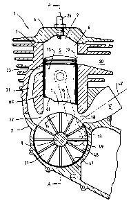
Referring now to figures 1 and 2, there is shown a two-stroke internal
combustion engine 1 comprising a crankcase 2, a cylinder component 3 and a
CA 02289604 1999-11-15
WO 98/51909 PC1'/AU98LOQ303
6
cylinder head 4, which together define the cylinder 5. The end 6 of the
cylinder
at the crankcase is open while the cylinder head forms a closed end 7 of the
cylinder to thus define a combustion chamber 8. A crankshaft 9 is rotatably '
mounted by means-of bearings 10 in the crankcase. The crankshaft 9 includes
a pair of flywheels 11 and 12 and a crankpin 13 connecting the flywheels.
When the engine is running the crankshaft rotates in the direction indicated
by
the arrow 14. A piston 15 reciprocates in the cylinder and is connected to the
crankshaft by a connecting rod 16.
The combustible mixture for the engine is formed in a carburetor (not
shown) and flows into the engine through an intake duct 17 which terminates
in an intake port 18 in the cylinder wall. The exhaust gases of the engine
flow
from an exhaust port 19 in the cylinder wall out through an exhaust duct 20. A
transfer passage 21, which extends between a crankcase transfer port 22 at the
crankcase end of the cylinder and a combustion chamber transfer port 23 at the
combustion chamber end of the cylinder, conveys fluid from inside the
crankcase 2 to the combustion chamber 8.
With a combustible mixture in the combustion chamber 8 and with the
piston at top-dead-center, a spark between the electrodes of the spark plug 24
will ignite that combustible mixture. The force created by that ignition will
drive the piston 1 S towards bottom-dead-center, with the crankshaft 9 turning
in the direction indicated by the arrow 14. When the moving piston 15 starts
uncovering the exhaust port 19 the burned gases are allowed to escape through
the exhaust duct 20. The moving piston will also have uncovered the intake
port
18 so that the combustible mixture at the crankshaft side of the piston is
compressed inside the crankcase 2 and the adjacent end of the cylinder. When
the piston 15 moves sufficiently far in the cylinder 5 to uncover the transfer
port 23 that compressed mixture flows from inside the crankcase 2 through the
transfer port 22, along the transfer passage 21 and into the cylinder 5
through
the transfer port 23. As the piston again returns to top-dead-center, its
covers
the ports 23 and 19 and opens the port 18. The opening of the intake port 18
CA 02289604 1999-11-15
WO 98/51909 PGT/AU98/00303
7
again permits the combustible mixture to flow from the carburetor into the
engine. The above-described cycle is then continuously repeated.
' The rotation of the crankshaft 9 inside the crankcase 2 in the direction
of the arrow 14 causes a rotation of the combustible mixture inside the
crankcase in the same direction. The rotation of the flywheels 1 l and 12 acts
to impart a flow to the combustible mixture immediately adjacent the periphery
of the flywheels in the direction of the arrow 14.
In order to take advantage of the momentum of this rotating combustible
mixture, the transfer port 22 located immediately adjacent the crankcase 2 is
located substantially radially with respect to the axis of rotation of the
flywheels
11 and 12. This way, the transfer duct 22 is effectively placed in the path of
the boundary layer rotating around the periphery of the flywheels 11 and 12
and
its momentum used to transfer this combustible mixture through the transfer
passage 21 into the combustion chamber 5. The efficiency of delivery of the
combustible mixture as well as the transfer time is found to be greatly
improved
with respect to known two-stroke internal combustion engines.
The relationship of the transfer passage 21 may be better appreciated by
referring to Figure 3, which shows a plan crass sectional view of the two-
stroke
engine shown in Figure 2. From this figure, it can be seen that the transfer
port
22 is located such that at least one plane of rotation of the flywheels 11 and
12
passes therethrough so as to directly transfer the combustible mixture
rotating
in the boundary layer around the periphery of the flywheels 11 and 12 directly
into the transfer passage 21. Preferably, one or more additional transfer
ports
40 and 41 may be provided adjacent to the first transfer port 21 to increase
the
volume of combustible mixture transferred from the crankcase to the
combustion chamber, thus improving the efficiency of the circulation of the
combustible mixture in the two-stroke engine 1.
Returning again to Figure 1, the intake port 18 and associated intake duct
17 are oriented so as to deliver the combustible mixture provided to the
engine
directly into the crankcase. In order to achieve this, the intake duct 17 may
be
CA 02289604 1999-11-15
W0 98/51909 PCT/AU98/00303
8
located such that its longitudinal axis 42 passes through one or more of the
flywheels 11 and 12. Combustible mixture delivered through the intake duct
in such an arrangement is delivered directly into the boundary layer
circulating
around the periphery of the flywheels 11 and 12. The delivery of this
combustible mixture into the transfer passage 21 is therefore optimized.
Additional measures may also be taken in order to optimism the
circulation of the combustible mixture within the engine. For example, the
intake duct 17, the transfer duct 21 and a plane of rotation of one or more of
the flywheels 11 and 12 may be located in substantially the same plane.
Advantageously, the combustible mixture introduced into the engine through the
intake duct 17 and transferred across the cylinder 5 into the txansfer passage
21
prior to use in the combustion chamber 5 and expulsion through the exhaust
duct 20, remains substantially within the same plane and is thus not subjected
to rapid changes in direction which would otherwise impair the efficiency of
delivery of the combustible mixture. The rapidity of delivery of the
combustible mixture as well as the general efficiency of the engine is
therefore
improved with respect to prior art two-stroke engines.
As a consequence of the forward location of the transfer port 22,
chambers located to either side of the exterior faces of the flywheels 11 and
12
- required in prior art two-stroke internal combustion engines in order to
deliver
combustible mixture in the crankcase 2 into laterally located transfer
passages -
are no longer required. The efficiency of operation of the engine may
therefore be improved by locating the interior surfaces of the crankcase
immediately adjacent the exterior faces of the flywheels 11 and 12. This is
best
appreciated from Figures 2 and 3, which show an exterior face 43 of the
flywheel 11 and an exterior face 44 of the flywheel 12 in close proximity to
interior surfaces 45 and 4b of the crankcase 2. In embodiments of the
invention
where only one flywheel is present, the exterior faces of the flywheel will be
constituted by both faces of that flywheel. In this sense, the word "exterior"
is
meant to refer to those faces of the flywheel or flywheels which are not
CA 02289604 1999-11-15
WO 98/51909 PCT/AU98/00303
9
adjacent a face of another flywheel. Accordingly, the volume of the crankcase
may be reduced, which results in a more efficient pumping of the combustible
' mixture being required by the engine and enables the rotational force of the
flywheels 11 and 12 to be more efficiently transferred to that combustible
mixture present within the crankcase 2.
In order to reduce turbulence and improve the laminar flow of the
combustible mixture circulating within the engine, the transfer port 23 has a
minimum radius 64 of 1.0 mm, and preferably 1.25 mm between the wall of the
cylinder 5 and the transfer passage 21. Preferably, the same minimum radius
is applied to the transfer ports associated with the combustion chamber end of
the additional transfer passages 40 and 41.
To the same end, the transfer port 22 has a minimum radius 65 of 2.0
mm, and preferably 2.5 mm, between the wall of the cylinder 5 and the transfer
passage 21. The same minimum radius may also be applied to the
corresponding transfer ports of the transfer passages 40 and 41. Preferably,
the
minimum radius 65 between the wall of the cylinder 5 and the transfer passage
progressively varies, for example, from a minimum of 2.0 mm at the wall of the
cylinder 5 to a minimum of 13.0 mm adjacent the transfer passage 21 such that
the transfer port 22 has a bell-shaped mouth.
Moreover, the transfer passages 21, 40 and 41 may each have a cross
sectional area which progressively decreases along their respective lengths
from
their crankcase end to their combustion chamber end. Abrupt changes in cross
sectional area and flow rates of the combustible mixture within these transfer
passages are therefore avoided. It has been found in practice that a
progressive
decrease of approximately 20% along the length of the transfer passage is
suitable for this purpose.
Another measure of improving the efficient delivery of combustible
mixture within the two-stroke internal combustion engine 1 is the provision of
one or more vanes 47, 48 and 49 on at least one of the faces of the flywheels
11 and 12. These vanes act to drive the combustible mixture present within the
CA 02289604 1999-11-15
WO 98/51909 PGT/AU98/00303
crankcase in the direction 14 of rotation of the flywheels 11 and 12.
Preferably,
these vanes 47, 48 and 49 extend radially along a face of the flywheels 11 and
12. Although only the exterior face 43 of flywheel 11 is shown as having vanes
'
of this nature, it is to be understood that more than one or all faces of the
5 flywheels mounted in the crankcase may be provided with such vanes.
In addition or as an alternative to the vanes 47, 48 and 49, peripherally
mounted vanes such as those referenced 50, 51 and 52 may be provided on a
peripheral surface of one or more of the flywheels 11 and 12 in order to drive
the boundary layer of combustible mixture around the periphery of the
10 flywheels 11 and 12. Such vanes may be provided on one or more or all of
the
flywheels mounted within the crankcase 2.
The vanes 47, 48 and 49 shown in Figure 1, as well as the vanes 50, 51
and 52 shown in Figures 2 and 3 may be provided by projections from the
flywheels 11 and 12 or by the provision of notches, grooves or other
1 S indentations in the flywheels 11 and 12.
Figures 2 and 4 show respectively a front view and a side view of the
piston 15. A front skirt 60 facing the transfer port 22 is contoured so as to
minimize the restrictive and turbulent flow of the combustible mixture into
the
transfer passage 21 when the piston 15 is near the bottom of its travel in the
cylinder 5. In that regard, the skirt 60 includes a recess 61 having a shape
substantially corresponding to that of the transfer port 22 and being
coincident
therewith when the piston 15 is near bottom-dead-centre. Additionally, the
skirt
60 may include additional recesses, such as those referenced 62 and 63, having
shapes corresponding to that of transfer ports 40 and 41 and being coincident
therewith when the piston 1 S is near bottom-dead-centre.
Since modifications within the spirit and scope of the invention may be
readily effected by persons skilled in the art, it is to be understood that
the
invention is not limited to the particular embodiment described, by way of
example, hereinabove.