Note: Descriptions are shown in the official language in which they were submitted.
CA 02289990 1999-11-16
COMPOUND BONE STRUCTURE FABRICATED
FROM ALLOGRAFT TISSUE
BACKGROUND OF THE INVENTION
1. Field of Invention
The present invention generally relates to allograft bone devices for surgical
implantation into bone tissue and particularly to a composite allograft bone
device
constructed from two or more separate bone pieces made from allograft,
autograft and
xenograft bone tissue that can be constructed to have dimensions that are
larger than the
dimensions of naturally occurring bone suitable for implantation in a surgical
site .
2. Description of the Prior Art
Allograft bone tissue is widely used in orthopedic, neuro-, maxillofacial,
podiatric and dental surgery. Allograft tissue is valuable in these fields of
surgery because
it is strong and it biointegrates well over time with the recipient patient's
tissue. Allograft
bone tissue can be shaped for specific surgical applications by the surgeon or
by a bone
product manufacturer in a manufacturing environment before the allograft bone
tissue is
transferred to the surgeon. Unfortunately because of the size limitation of
the bone
material only devices of a certain size could be constructed.
Surgical implants constructed entirely from allograft bone tissue are
generally superior to implants constructed from synthetic or nonabsorbable
polymers or
metals because allograft bone tissue is bioinert and integrates well with the
surrounding
tissues.
Allograft bone occurs in two basic forms: 1 ) cancellous bone (also referred
to as trabecular bone) and 2) cortical bone. Cortical bone is highly dense and
has a
compound structure comprised of calcium hydroxyapatite reinforced with
collagen fiber.
This cortical bone material is the predominant load bearing component of long
bones in the
human body. Many shapes and forms can be fabricated from allograft cortical
bone tissue
including pins, screws, plates, intervertebral discs and the like for use in
human surgery.
Cortical bone has one serious limitation that plastics and metal do not have.
Bone parts and
bone products made from allograft cortical tissue are limited in size,
dimension and shape
because of the anatomical limits on the thickness and length of the source
bone.
As an example, the largest long bone, the femur bone, has a thick cortical
wall that varies in thickness from about two millimeters to about ten
millimeters. The
majority of the femoral cortical bone wall typically ranges from about three
millimeter to
CA 02289990 1999-11-16
2
about eight millimeters in thickness. The length of the cortical tissue is
also naturally
limited by the size and the weight of the allograft tissue donor. Accordingly,
specific
implants fabricated from cortical bone have previously not been larger than
these natural
anatomical dimensions. The other long bones of the human body, the Numerous,
the tibia,
the fibula, the radius, the ulna, the ribs, etc., are similarly limited in
dimension. Shaped
implants made from these other long bones are also necessarily limited in
dimension.
The dimensional limit that has been achieved with single piece cortical bone
is about lOmm x about l3mm cross-sections. The length of these sections can be
much
longer as they are taken from the long axis of the bone. The research that has
been
completed shows femoral sections ranging from 3mm x 4mm to l Omm x l Omm at
the mid-
shaft and tibial sections 3mm x 6mm to lOmm x l3mm at the proximal end.
Many medical problems and surgical procedures require implants largerthan
have previously been made out of allograft cortical tissue. It is desirable to
have a surgical
implant made entirely out of allograft cortical tissue that is larger than can
be made from
a single piece of naturally occurring bone. Two requirements must be met by
any implant
fabricated entirely from cortical bone, however, to achieve a successful
surgical result.
First, the components must be held together in such a way that the mechanical
structure of
the implant is not compromised during the surgical implantation procedure.
Many surgical
implants are implanted in the recipient patient with a large applied force.
Many implants
are actually hammered in as is the case for an intervertebral implant. Second,
the
compound structure of the implant must hold together during the post-operative
period
during which the allograft tissue is resorbed and remodeled.
The prior art contains many references directed to fasteners, spinal cages
and devices which are constructed of inert metals or plastics which are used
in bone repair.
There are relatively few devices used in bone repair constructed of allograft
bone because
of the difficulty in obtaining and shaping the material and the natural limits
placed on the
size of the device based on the constraints of the sizes of the natural bone
which can be
shaped to form devices of a larger required size.
One example of an allograft device is disclosed in U.S. Patent Number
4,877,020 which shows a dowel made of bone having a helicoidal thread.
Another device is shown in U.S. Patent Number 4,932,973 where the use
of a perforated bone matrix for use in insertion or implantation in a bone
mass to promote
CA 02289990 1999-11-16
J
bone growth is disclosed.
Similarly U. S. Patent Number 5,112,354 discloses the preparation of an
allograft bone segment for use in skeletal reconstruction. The bone segment is
demineralized and a multiplicity of bores (described as pores) are drilled
into the bone
mass in a pattern to maximize the surface area of the implant. Some of the
bores are drilled
through the bone mass at the center of the hexagon pattern.
U.S. Patent Number 5,439,684 is directed toward various swollen
demineralized bone constructions such as sleeves, rectangular pledgets and
wedges. The
pledgets and wedges can be used as invertebrate support blocks. The bone can
be
machined into a desired shape for implantation such as sheet, disc, ring,
cube, cylinder or
sliced and wrapped into a tubular shape. However, all of these bone structures
are limited
to the size and shape of the original material.
Another patent of interest is U.S. Patent Number 4,858,603 which shows
a bone pin which is placed through an angular bore cut through two separate
pieces of bone
to hold the pieces together in a fixed secured relationship. The bone pin is
made from a
polymer which is absorbable in an animal body.
Until now, the only way that separate bone pieces could be joined together
to arrive at a larger device has been to tongue and groove the respective
pieces which
creates shearing areas and limits the use to which such constructed device
could be used.
This is a significant problem where a device is placed under stress and
shearing forces as
for example where it is hammered into place between vertebrae or into other
bone areas.
The first disclosure of joining together separate pieces of allograft bone is
believed to be
set forth in various articles by F. Albee. This disclosure also show the
machining of
dowels, pins and screws from bone. F. Albee, Bone Graft Surgery in Disease
Injury and
Deformity p. 22 (1940); and F. Albee, The Improved Albee Bone Mill, American
Journal
of Surgery p. 657 (March 1938).
Accordingly, there is a need for implantable shaped structures made entirely
out of cortical bone tissue that are larger than naturally occurring bone
structures and are
made wholly out of cortical tissue without using external, non-cortical
fasteners or
adhesives.
SUMMARY OF THE INVENTION
CA 02289990 1999-11-16
4
The present invention is directed toward a shaped structure made out of
allograft cortical bone tissue that is larger than the natural dimensions of a
cortical bone
layer made by combining two or more smaller pieces to form a compound bone
structure.
The compound bone structure is comprised of a first bone member having
a first mating face constructed and arranged to support a load applied in a
direction that is
normal to the first mating face and to receive and engage a complimentary
mating face of
a second bone member. The second bone member has a mating face that is
complimentary
to the first mating face of the first bone member. The second mating face is
constructed
and arranged to support.a load applied in the direction normal to the second
mating face
and to engage the first mating face so that the first and second bone members
cooperate to
form the compound bone structure.
The compound bone structure has an exterior surface that can be shaped to
form an implant that can support the anatomical load and orient the implant in
the surgical
site so that the anatomical load is applied to the engaged first and second
mating faces in
the normal direction. Complimentary mating structures formed on the first and
second
mating faces prevent displacement of the first bone member with respect to the
second
bone member in both a longitudinal direction and a transverse direction when
an
anatomical load is applied.
At least one pin is placed through the component bone members of
compound bone structure at an oblique angle to the plane of the mating faces
and extends
through the full thickness of the compound bone structure.
It is an object of the invention to make a compound bone structure from
bone tissue of smaller bone segments for use in implantation into a surgical
site and to
support an anatomical load applied to the compound bone structure during a
post-operative
period while the implanted bone tissue is resorbed and remodeled.
It is another object of the invention to fabricate shapes out of allograft
cortical tissue that would enable larger parts to be made out of cortical
tissue without using
external non-cortical fasteners or adhesives.
It is yet another object of the invention to form a compound bone structure
which is implantable and is larger than bone pieces that are found in nature.
These and other objects, advantages, and novel features of the present
invention will become apparent when considered with the teachings contained in
the
CA 02289990 1999-11-16
detailed disclosure along with the accompanying drawings.
BRIEF DESCRIPTION OF THE DRAWINGS
FIG. 1 shows an exploded flipped perspective elevational view of the
inventive compound bone device;
FIG. 2 shows a top plan view of one of the bone members of the inventive
compound bone device shown in Figure 1;
FIG. 3 shows an end elevational view of the bone member shown in Figure
2;
FIG. 4 shows a top plan view of a second member of the inventive
compound bone device shown in Figure l;
FIG. 5 shows an end elevational view of the bone member shown in Figure
4;
FIG. 6 shows an assembled perspective elevational view of the inventive
compound bone device with the respective mating faces in phantom and an
inserted dowel;
FIG. 7 shows an exploded flipped perspective view of the inventive
compound bone device with dowel removed and the dowel bore in phantom;
FIG. 8 shows an exploded side elevational view of another embodiment of
the compound bone device;
FIG. 9 is an assembled side elevational view of the compound bone device
of FIG. 8 showing the dowels removed and dowel bores in phantom;
FIG. 10 is an plan view of the first bone member taken along line 10'-10'
in FIG. 8;
FIG. 11 is a plan view of the second bone member taken along line 11'-11'
in FIG. 8;
FIG. 12 is a side elevational view of the compound bone device shaped to
form an implant for insertion between vertebra for spinal fusion with the
bores shown in
phantom;
FIG. 13 is a cross-sectional view of the compound bone device of FIG.12
taken along the center axis of the device;
FIG. 14 is a schematic view of the compound bone device shown in Figures
12 andl3 in a surgical site formed between an upper and a lower vertebrae in
lumbar
CA 02289990 1999-11-16
6
portion of a spine; and
FIG. 15 is an exploded perspective view of an alternative embodiment of
a smooth outer surfaced compound bone device.
DETAILED DESCRIPTION OF THE PREFERRED EMBODIMENT
The preferred embodiment and the best mode of the invention is shown in
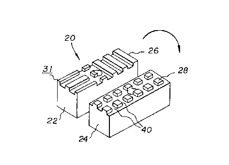
FIGS. 1-7. Figure 1 shows an exploded side view of a compound bone device 20
with a
first bone member 22 and a second bone member 24 flipped for viewing. The
first and
second bone members 22, 24 are constructed from rectangular blocks of bone
tissue that
have been machined or shaped by other suitable means. Each bone member 22, 24
has a
mating face or engagement surface 26 and 28 as shown in Figures 2 and 4
respectively that
has been shaped to form integral mating projections or teeth 30 on each face
26, 28 so that
the members 22, 24 can be engaged to form the compound bone device 20 shown in
FIG.
6.
Bone member 22 has a mating face 26 constructed with three bar projections
31 separated by grooves 32 formed on one end. The bar projections 31 run
parallel to the
longitudinal axis of the bar member and extend along the mating face less than
'/Z the
length of the bar member. The grooves 32 are preferably around 2 to 2. l2mm in
width and
the side bars 31(a) have a width which is less than the width of the center
bar 31(b). The
other end of the bone member 22 has three bar projections 33 separated by
grooves 34
running transverse the longitudinal axis and extending across the width of the
bone member
22. The midsection of the bone member has a plurality of rectangular
projections 35
formed by extending grooves 32 up to the side wall 36 of the inner transverse
bar 33. The
rectangular projections 35 are separated from the axially aligned bar members
31 by a
groove 37 and the side wall 36 of inner transverse bar 33 by groove 37(a). The
bars 31(b),
33 and center rectangular projection 35(a) have a width of approximately 2mm.
Bone member 24 is formed with grooves 38 along each longitudinal side
of the body and is also provided with a central groove 39 extending
longitudinally the
length of the bone member 24. Grooves 40 run across the width and transversely
intersect
grooves 38 and 39 forming projections 30. The grooves 38 located on opposite
sides of
the bone member 24 receive the side bars 31(a) and the side rectangular
projections 35.
The mating projections or teeth range from .5 to 2.Omm in height,
CA 02289990 1999-11-16
7
preferably l.Omm and are formed by cutting a plurality of slots, grooves or
channels
ranging from 1 to 4mm in width with a generally rectangularly shaped cross
sections in
each mating surface 26, 28 of the bone members. The channels or grooves 38-40
are of
equal width dimensions and preferably have a width ranging from 2.Omm to
2.12mm
apart.
The mating projections 30 and the channels on the bone members 22, 24
form complimentary inverse patterns that allow the members 22, 24 to be
engaged or
meshed together by press fitting the patterns together. This engagement and
relationship
of the various projections prevents relative motion between the members 22, 24
in both the
transverse and longitudinal directions to stabilize the compound bone device
20 during
subsequent machining of the exterior surface of the device 20 and during or
after
implantation in a surgical site.
Two biased or angled bores 42 and 43, respectively, extend through each
bone members 22, 24. The bores 42 and 43 are shown in phantom in FIGS. 6 and
7. The
bores 42 and 43 are oriented so that when the members 22, 24 are engaged, the
bores 42
and 43 are axially aligned to form a continuous first bore 47 through the
compound bone
device 20. A cylindrical pin 46 shown in FIG. 6 preferably made of cortical
bone tissue
is press fit into the continuous bore 47 to prevent the separation of the
members 22, 24.
Thus, the mating surfaces 26, 28 of the bone members 22, 24 are secured
together by at least one pin positioned at an oblique angle to the plane of
the engaged
mating surfaces and extending the full thickness of the compound bone device
20. In the
preferred embodiment shown in FIGS. 1-7, the wall surrounding bore 47 is
cylindrical and
pin 46 is cylindrical. The pin has a diameter slightly greater than the
diameter of the bore
47 so that the pin is retained in the bore by an interference fit and is
constructed with a
tolerance of 0.03mm to 0.25mm with respect to the bore diameter. If desired a
suitable
medical adhesive can be use to insure that the pin stays in the bore during
insertion.
It will be appreciated that three or more bone members can be fastened
together by forming projections on both sides of the bone members. As an
example, bone
member 24 could be provided with an identical mating face on its opposite side
which
would engage another bone member shaped identical to bone member 22.
Figure 8 shows an alternative embodiment of the compound bone device
120 constructed with a first bone member 122 and a second bone member 124. The
first
DEC 29 '99 10~07RM MOFFRT MRCERR 613 235 2508 P.2
~'1.
g
and second bone members 122, 124 are constructed from rectangular blocks of
bone tissue
that has been machined or shaped by other suitable means. Each bone member
122, 124
has a mating face or surface 126 and 128 as shown in Figures 10 and 11
respectively that
has been shaped to form integral mating projections or teeth 130 on each face
126, 128 so
that the me~nnbezs 122, 124 can be engaged to form the compound bone device
120 shown
in FIG. 9.
Each bone member 122, 124 has been shaped to form a groove 131 on each
longitudinally extending side of each member so that when the members are
engaged as
shown in FIGS. 9 and 12, a composite groove 133 extends longitudinally the
length of the
compound bone device 120. The groove 133 is located on opposite sides of the
compound
bone device 120 and serves as a holding slot for the instrument which holds
the compound
bone device 120 while it is being machined, One end of each bone member 122,
124 has
been machined to provide a slightly extended end surface 134, The raised end
surfaces 134
cooperate when the members 122, 124 are engaged to form an impact surface 135
that can
be struck with a hammer or other suitable in8trument during a surgical
procedure tv implant
the compound bone device 120 into a surgical site.
The mating projections or teeth 130 range from .5 to 2.Omm in height,
preferably l.Omm and are formed by cutting a plurality of slots, grooves or
channels 132
ranging from 1 to 4mm in width with a generally rectangular shaped cross
section in each
mating surface 126, 128 of the bone tissue. The chatlnels 132 are of equal
dimensions and
are preferably equally spaced about 2.Omm to 2.12mm apart. The channels 132
are
preferably angled at +45 degrees and -45 degrees with respect to the
longitudinally
extending grooves 131.
The mating projections or teeth 130 formed by the channels 132 are
comprised of a.~plurality of identical longitudinally spaced rectangular
projections in a
central portion of each mating eurfa~ce 126, 128. A larger triangular shaped
projection 136
extends transversely between the longitudinal edges at one end of each of the
mating
surface 126, 128. The triangular shaped projection 136 has the same height as
the
projections 130.
The mating projections 130 and the channels 132 on the bone members 122,
124 form complimentary inverse patterns that allow the members 122, 124 to be
engaged
or meshed together by press fitting the patterns together. This engagement
prevents
CA 02289990 1999-11-16
CA 02289990 1999-11-16
9
relative motion between the members 122, 124 in both the transverse and
longitudinal
directions to stabilize the compound bone device 120 during subsequent
machining of the
exterior surface of the device 120 and during or after implantation in a
surgical site.
As shown in FIGS.10 and 11, the channels 132 are machined in the cortical
bone to preferably a lmm depth and are angled at +4S degrees and -4S degrees
in relation
to edge 131 of each member 122, 124. The plus and minus 4S degree angles are
the
preferred angles for forming complimentary patterns on each surface 122, 124
because of
ease of manufacturing, but any angle within a range of from about 1 S degrees
to about 7S
degrees could be used in a similar way to cut other patterns forming mating
surfaces 126,
128. It is understood that a degree of tolerance is necessary in the
manufacturing process
to assure that the members 122, 124 can be engaged and still provide
sufficient structural
support to the compound bone device 20. In all of the described embodiments,
the
maximum tolerance between the engaged parts at the surface ranges from .02Smm
to
.1 mm.
Two biased or angled bores 142, 144 and 143, 145, respectively, extend
through each bone member 122, 124. The bores 142, 144, 143, 14S are shown in
phantom
in FIGS. 8 and 9. The bores 142, 144, 143, 14S are arranged so that when the
members
122, 124 are engaged, the bores 142, 144, 143, 14S are axially aligned to form
a
continuous first bore 147 and a continuous second bore 149 through the
compound bone
device 120. Two cylindrical pins 146 shown in exploded view in FIG. 8
preferably made
of cortical bone tissue are press fit into each the continuous bores 147, 149
to prevent the
separation of the members 122, 124.
Thus, the mating surfaces 126, 128 of the bone members 122, 124 are
secured together by at least one pin positioned at an oblique angle to the
plane of the
engaged mating surfaces and extending the full or partial thickness of the
compound bone
device 120. The wall surrounding each bore 147, 149 is cylindrical and each
pin 146 is
cylindrical. The pin has a diameter slightly greater than the diameter of the
bores 147, 149
so that the pins are retained in the bores by an interference fit and is
constructed with a
tolerance of 0.03mm to 0.2Smm with respect to the bore diameter. If desired a
suitable
medical adhesive can be use to insure that the pins stay in the bores during
insertion. It can
be appreciated that the bores and pins can have other configurations as, for
example,
rectangular, triangular and the like. When the bone members 122, 124 are
engaged and
10
the pins 146 are inserted to hold them together, an exterior surface 148 of
the compound
bone device 120 can be shaped to form a suitable implant device for
implantation into a
surgical site. If desired, the exterior surface 48, 148, 248, 348 can be
scored 59, 259 or
otherwise configured to present gripping means which grips surrounding tissue
when the
compound bone device is implanted into the surgical site. The pins 146 provide
sufficient
structural reinforcement for the compound bone device to allow the device 120
to be
machined to form the desired shape. Another compound bone device 220 is shaped
so that
when the device 220 is implanted in a surgical site, the anatomical load of
the patient is
applied in a direction that is normal to the engaged mating faces 226, 228.
The normal
direction is shown in FIG. 15 by an arrow N. It can be appreciated from the
cross-section
that when the two members 222, 224 are engaged, the projections on the first
member 222
are disposed between or adjacent channels on the second member 224 to prevent
the
relative movement between the members 222, 224 in the longitudinal and
transverse
directions. There are some empty spaces between the mating faces 226, 228 of
the
compound bone device 220.
FIGS. 12, 13 and 14 show that the exterior surface 248 of the compound
bone device 220 can be shaped to form a intervertebral implant for the lumbar
spine for
insertion between vertebrae to fuse the vertebrae. The compound bone device
220 can be
machined to provide a sloped and rounded proximal end 250 and distal end 252
for easy
intervertebral insertion.
FIG. 13 shows a cross-section of a compound bone device 220 taken
through FIG. 12. The cross-section shows that the bores 247, 249 are angled
with respect
to the normal direction N. It can be appreciated that the normal direction is
generally
perpendicular to each of the engaged surfaces of the compound bone device 220.
Each
mating face 226, 228 is constructed and arranged to support a load that is
applied in a
direction that is normal to the surface. When the surfaces are engaged they
can support an
applied normal load and, because they are engaged, the normal load will not
displace the
bone members 222, 224 in the longitudinal or transverse directions relative to
one another.
The bores 247, 249 generally form oblique angles with the engaged
surfaces. It can be appreciated from FIGS. 12 and 13 that the oblique angles
of the bores
247, 249 are complimentary. That is, the angle of bore 247 is the inverse of
or the negative
of the angle of bore 249. The preferred angle of bore 247 with a line
generally extending
11
between the two faces is about 110 degrees and therefore the angle of bore 249
is negative
110 degrees.
FIG. 14 shows a schematic representation of the compound bone device 220
implanted in a surgical site 62 in the lumbar spine between an upper vertebra
64 and a
lower vertebra 66 to fuse the vertebra. In this surgical procedure, an
intervertebral space
is enlarged and shaped to receive the allograft compound bone device 220
implant. The
compound bone device 220 is inserted in the surgical site 62 so that the
applied anatomical
load N is applied in a direction that is normal or perpendicular to the
engaged mating faces
226, 228.
The exterior surface 248 of the compound bone device 220 is shaped to
support the applied load in a direction that is normal to the engaged faces
226, 228 and to
maintain the orientation of the implanted compound bone device 220 in the
surgical site
62 throughout the post-operative period.
The engaged faces 26, 28, 126, 128, 226, 228 and 326, 328 support the
major anatomical load of the patient during the post operative recovery
period. The
engagement between the respective projections 30, 130, 230 and 330 on the two
mating
faces 26, 28, 126, 128, 226, 228 and 326, 328 assure that the first and second
bone
members 22, 24, 122, 124, 222, 224 and 322, 324 do not move relative to one
another in
the longitudinal or transverse directions during the post operative period.
It is desired that the compound bone devices 20, 120, 220 and 320 hold
together during the post operative period to allow resorption and remodeling
to occur in
the allograft tissue and pins are used to hold the same together. The pins 46,
146 (pins 246
not shown), 346 inserted in bores 47; 147, 149, 247, 249 and 347 can be made
of cortical,
allograft tissue. The outer surface of each cortical pin is entirely within
and surrounded by
the bone mass of the compound bone device so that the pin is substantially
protected from
the biochemical attack that occurs from normal biological and biochemical
processes as the
implant is integrated into the bone of the patient. Only the end surfaces 446
and 546 of the
pin 46, 146 are exposed, but this results in minimal structural degradation of
each pin.
The biological and biochemical process cause a slow absorption of the
implanted bone to occur over time. This absorption could structurally degrade
the
interlocking bone members of the compound bone device. Because the anatomical
load
is normal to the mating complimentary surfaces, the anatomical load can be
sustained even
_. ._. .~_ . . ._ ._ _._~. ~ _ __._ ...._.__~.~.~....._..~... . _ _ ._ _._..
.~..~... _ _ __ .
12
during tissue degradation. Because the pins are substantially protected from
the
biochemical mechanism of absorption, the pins will continue to secure the bone
members
together long enough to allow full healing and integration to occur. The
cortical pins 46,
146 and 346 are embedded and held tightly in the mass of the implant and are
protected
from the biochemical attack of the patient except at the two end surfaces 446
and 546 of
each pin. The pins 46, 146, and 346 remain structurally intact during the post-
operative
period to help maintain the structural stability of the compound bone device
20, 120, 220
and 320.
The normal absorption mechanisms that occur during the healing process
also tend to structurally degrade the two engaged bone members of the compound
bone
device 20, 120, 220 and 320 during the post operative period. Because the
anatomical load
is normal to the engaged surfaces, the applied load can be supported by the
device 20, 120,
220 and 320 even though some degradation of the allograft tissue does occur.
Because the
length of the interlocking pins 46, 146 and 346 are protected from biochemical
degradation, the pins continues to secure and hold the two bone members 22,
24; 122, 124;
222, 224 and 322, 324 in place long enough for full resorption and remodeling
to occur.
The cortical tissue of the compound bone device 20, 120, 220, and 320 has been
observed
to last 6 to 12 months before being fully integrated into the host patient.
The assembled compound bone device 220 shown in the schematic view in
FIG. 14 was tested in a cadaver lab in which it was inserted into the lumbar
spine. The
procedure requires that the assembly be hammered using considerable force into
the
intervertebral disc space. Four compound bone devices were successfully
inserted into the
spine with no signs of impact damage due to the insertion.
Another embodiment of the compound bone device 320 is shown in FIG.
15 which shows a first bone member 322 and a second bone member 324 in
exploded view
with a pin 346. The mating faces 326, 328 and projecting teeth 330 can be
engaged and
secured together with pin 346 to form the compound bone device 320. The
exterior 348
has been shaped to form a rectangular shape with rounded corners.
It can be understood by one skilled in the art that the preferred embodiment
described above is intended as an example only to teach the broad principles
of the
invention and is not intended to be limiting. It can be understood, for
example, that the
mating projections or teeth 30, 130, 230, 330 are constructed and arranged so
that when the
13
two mating faces 26, 28 and 126, 128 and 226, 228 and 326, 328 are engaged,
there is no
significant relative movement between the bone members in the longitudinal and
transverse
directions outside of that permitted by the manufacturing tolerances and by
any structural
changes that occur in the bone device during the post operative period.
It is appreciated that many geometric configurations of projections on each
mating face can provide suitable structures to prevent relative movement
between the bone
members in the longitudinal and transverse directions.
In general, a plurality of mating projections and channels forming mating
spaces are provided on a first mating face and a plurality of mating
projections and mating
spaces are provided on a second mating face. When the faces are engaged or
mated, the
mating teeth on the first face are disposed within the mating spaces on the
second mating
face and the mating teeth on the second mating face are disposed within the
mating spaces
on the first mating face to prevent the relative movement between the bone
members in the
longitudinal and transverse directions when the bone members are inserted into
a surgical
site or are disposed in a surgical site during a post operative period.
In general, each mating face is constructed and arranged to support an
applied load applied in a normal direction and to engage a mating face with
complimentary
projection receiving construction.
The two piece design for the compound bone devices described above allow
for constructions l Omm x 25mm or larger. This assembly technique considerably
broadens
the use of allograft tissues by allowing much larger implants to be formed
than could have
been attained from the normal human anatomy.
It can also be understood that because the preferred embodiment is
illustrative only, as it is contemplated to provide a compound bone device
comprised of
more than two bone members. In such a case, the compound bone device can be
thought
of as being comprised of an upper member, a middle members) and a lower
member. The
upper and lower members are provided with a single mating face and the middle
members) is provided with two mating faces generally disposed on opposite
sides thereof
so that the three or more bone members or pieces can be engaged and pinned
together with
at least one embedded cortical bone pin, preferably located at an oblique
angle to the
longitudinal plane of the mating surfaces.
Because bones are irregularly shaped and because not all applications of the
14
invention require that the implant support an anatomical load that is applied
in generally
one direction, it can be understood that if more than one pair of engaged
mating faces is
present in a single compound bone device, the pairs need not necessarily be
parallel nor do
the individual members of each pair have to be generally planar to form a
compound bone
device.
The compound bone device can be constructed and arranged to support a
load applied in a direction that is generally normal to the two pairs of
engaged faces so that
the bone device can support an anatomical load and prevent the relative
displacement of
the three bone pieces in a longitudinal or transverse direction.
It can further be understood that because the illustrated embodiment is
exemplary only, it is contemplated to provide compound bone devices which are
shaped
for many applications and that the compound bone device design is not
restricted to use in
the lumbar spine for spinal fusion. A compound bone device comprised of two or
more
bone members can be shaped during the manufacturing process to form compound
bone
pins, bone screws, plates, discs, wedges , blocks and other devices of various
configurations.
The compound bone device can be fabricated from xenograft, autograft or
allograft bone tissue, and it is contemplated to use any suitable bone tissue
from any source
to form a compound bone device.
It is also understood that although it is preferred to fabricate the compound
bone device using only cortical bone without the use of adhesives or synthetic
absorbable
or nonabsorbable polymers or metals, it is within the scope of the invention
to additionally
secure together the bone members with any suitable surgical bone adhesive or
with a
synthetic absorbable or nonabsorbable polymer or in any combination with or
without at
least one pin made of bone tissue.
In the foregoing description, the invention has been described with reference
to a particular preferred embodiment, although it is to be understood that
specific details
as shown are merely illustrative, and the invention may be carried out in
other ways
without departing from the true spirit and scope of the following claims.
_.... __.... ._...v~.~....~._....~._.._~...___.... ._.__
..~......~u..w......._._..._..~._..W_._~..~.~....v_.~...~.._..