Language selection

Search

Patent 2290023 Summary

Third-party information liability

Some of the information on this Web page has been provided by external sources. The Government of Canada is not responsible for the accuracy, reliability or currency of the information supplied by external sources. Users wishing to rely upon this information should consult directly with the source of the information. Content provided by external sources is not subject to official languages, privacy and accessibility requirements.

Claims and Abstract availability

Any discrepancies in the text and image of the Claims and Abstract are due to differing posting times. Text of the Claims and Abstract are posted:

  • At the time the application is open to public inspection;
  • At the time of issue of the patent (grant).
(12) Patent Application: (11) CA 2290023
(54) English Title: METHOD OF MAKING ENDMILLS
(54) French Title: PROCEDE DE PRODUCTION DE FRAISES
Status: Deemed Abandoned and Beyond the Period of Reinstatement - Pending Response to Notice of Disregarded Communication
Bibliographic Data
(51) International Patent Classification (IPC):
  • B23C 05/10 (2006.01)
  • B23B 27/18 (2006.01)
  • B23P 15/34 (2006.01)
(72) Inventors :
  • LITTECKE, PETER (Sweden)
(73) Owners :
  • SANDVIK AB
(71) Applicants :
  • SANDVIK AB (Sweden)
(74) Agent: GOWLING WLG (CANADA) LLP
(74) Associate agent:
(45) Issued:
(86) PCT Filing Date: 1998-06-10
(87) Open to Public Inspection: 1998-12-17
Availability of licence: N/A
Dedicated to the Public: N/A
(25) Language of filing: English

Patent Cooperation Treaty (PCT): Yes
(86) PCT Filing Number: PCT/SE1998/001113
(87) International Publication Number: SE1998001113
(85) National Entry: 1999-11-09

(30) Application Priority Data:
Application No. Country/Territory Date
9702297-4 (Sweden) 1997-06-13

Abstracts

English Abstract


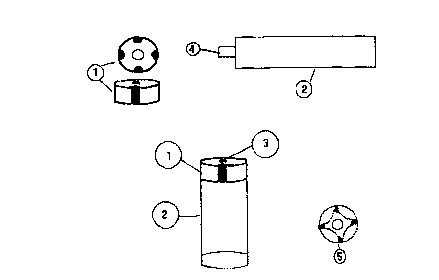
The present invention relates to an endmill provided with cutting edges of cBN
or PCD and consisting of a shank part and a part containing the cBN or PCD
brazed to the shank. The latter part is in the form of a disc in which the
superhard material is present in a groove in the envelope surface and extends
from one end surface to the other. After brazing the disc to the shank, the
body obtained is ground to an endmill with cutting edges formed of superhard
material. In a preferred embodiment, the shank is provided with a tenon
against which the part containing the superhard material is brazed. This
minimises the risk of braze joint failure and provides an endmill with several
cutting edges which can be achieved at a low cost.


French Abstract

L'invention concerne une fraise dotée d'arêtes de coupe en nitrure de bore cubique ou en diamant polycristallin, comprenant une partie queue et un élément contenant le nitrure de bore cubique ou le diamant polycristallin. Cet élément, fixé à la queue par brasage, a la forme d'un disque dans lequel le matériau extra-dur est présent dans une rainure pratiquée à la surface de l'enveloppe et s'étend de la face d'une extrémité à la face de l'autre extrémité. Une fois le disque fixé à la queue par brasage, le corps ainsi obtenu est usiné pour donner une fraise dotée d'arêtes de coupe en matériau extra-dur. Dans un mode de réalisation préféré, la queue est dotée d'un tenon sur lequel l'élément contenant le matériau extra-dur est fixé par brasage. Cela réduit le risque de défaillance aux points de brasage et permet la fabrication à faible coût d'une fraise pourvue de plusieurs arêtes de coupe.

Claims

Note: Claims are shown in the official language in which they were submitted.


4
Claims
1. Endmill provided with cutting edges of cBN or PCD
and consisting of a shank part and a part containing the
cBN or PCD brazed to the shank characterised
in that said shank is provided with a tenon against
which the part containing the superhard material is
brazed.
2. Endmill according to the preceding claim
characterised in that said tenon is round.
3. Endmill according to claim 1
characterised in that said tenon is tapered.
4. Endmill according to claim 1
characterised in that said tenon is of
non-round shape.
5. Endmill according to claim 1
characterised in that said tenon extends at
least part way into the part containing the superhard
material.
6. Method of making an endmill provided with at
least one cutting edge of cBN or PCD and consisting of a
shank part and a part containing the cBN or PCD
characterised in comprising the steps
providing a cemented carbide disc preferably with a
cylindrical cross section provided with at least one
body of a superhard material in a groove in the envelope
surface and extending from one end surface to the other
brazing said cemented carbide disc to a shank
grinding the obtained body to form an endmill with
cutting edges formed from the superhard material.
7. Method according to claim 6
characterised in that said cemented carbide
disc is made using the following steps
providing a cemented carbide bar
grinding at least one groove in said bar

5
filling said groove with a powder mixture containing
cBN and/or diamond
heat treating said cemented carbide bar at a
temperature and pressure where cBN and/or diamond is
stable and cutting said bar into discs.
8. Method according to claim 6
characterised in said cemented carbide disc
is made using the following steps
providing one or more cemented carbide discs
grinding at least one groove in said discs
filling said groove in said discs with a powder
mixture containing cBN and/or diamond
heat treating said cemented carbide discs at a
temperature and pressure where cBN and/or diamond is
stable whereby the discs are separated from each other
in such a way that they do not sinter together.
9. Method according to any of claims 6 - 8
characterised in the step of brazing said
shank part to the part containing the superhard material
with the aid of a tenon formed in the end of said shank
part and a hole extending at least partway through said
part containing the superhard material.
10. The product according to any of claims 6 - 8.

Description

Note: Descriptions are shown in the official language in which they were submitted.


CA 02290023 1999-11-09
WO 98/56528 PCT/SE98/01113
1
Method of making endmills
This invention relates to an endmill with cBN (cubic
boron nitride) or PCD (polycrystalline diamond) in the
cutting edges and a method of making the same. The
purpose of the method is to decrease the cost compared
to existing methods.
An endmill is used for machining of grooves, pockets
and slots and consists of a cylindrical holder with
cutting means at the end. It can be made of high speed
steel, or solid cemented carbide, but it can also
consist of a steel holder with cemented carbide inserts
as cutting means. For certain applications metal cutting
inserts having cutting edges formed of a superhard
material, such as PCD, are usually used for the
machining of non-ferrous alloys such as brass, magnesium
and aluminium, and the like, whereas inserts with
cutting edges formed of a superhard abrasive, such as
cBN are usually used for the machining of cast iron and
hardened steel and the like.
There are several types of PCD or cBN endmills on
the market today. Essentially there are two different
methods to manufacture them. One method includes
sintering cBN or diamond powder under elevated pressure
and temperature into a solid cylindrical body which is
then brazed onto a shank and finished into an endmill.
The other method includes bonding a layer of cBN or
diamond under elevated pressure and temperature to a
substrate, usually a cemented carbide disc, from which
smaller pieces, "chips", are cut out. These chips are
then brazed onto a cemented carbide rod and ground to
the finished shape. Tools produced that way are normally
quite expensive due to the many steps the product must
undergo before it is finished.
CONFIRMATION
coPY

CA 02290023 1999-11-09
WO 98/56528 PCT/SE98/01113
2
The object of the present invention is therefore to
provide a method, where an endmill with several cutting
edges can be achieved but at a substantially lower cost.
Fig 1 shows the principle of the method where
1 is the element that will form the cutting part,
2 is the shank
3 is the braze joint and
4 is a tenon
5 is a top view of the element 1 after shaping to
expose the cutting edges.
According to the method of the present invention the
starting point is a cemented carbide disc preferably
with a binder phase content of >10 wt-% provided with
superhard bodies according to the teachings of US
5,676,496. The cemented carbide disc is made from a
cemented carbide rod with a circular, square, triangular
or other suitable cross section preferably with a center
hole. Into this rod one or more grooves are ground
throughout its whole length and parallel to its axis.
The groove can be straight but it can also be helical.
The number of grooves and their location depend on the
type of disc that is to be produced. The shape of the
grooves can be made in different ways. It is important,
however, that they have a rounded or plane shape. Their
size shall be such that the cutting work essentially is
performed by the superhard material. After HP/HT
sintering the rod is cut into discs of desired
thickness.
Alternatively, in one or more cemented carbide discs
at least one groove is ground and filled with a powder
mixture containing cBN and/or diamond after which the
discs are treated at a temperature and pressure where
cBN and/or diamond is stable. During this treatment the
discs are separated from each other in such a way that
they do not sinter together.
I I T

CA 02290023 1999-11-09
- WO 98/56528 .~ PCT/SE98/01113
The shank 2 is preferably made in cemented carbide
preferably with a binder phase content of >10 wt-%. The
diameter of the shank is somewhat smaller than the
diameter of the disc with superhard materials. The other
end of the shank is provided with clamping means.
The PCD/cBN disc is then brazed together with the
shank.
In a preferred embodiment the end of the shank where
the PCD/cBN disc is brazed is ground down to form a
tenon, 4. The shape of the tenon is generally
cylindrical but it may alternatively be tapered, square,
triangular, elliptical or other non-round shape. The
diameter (or equivalent) of the tenon is about 15 - 40
of the diameter of the shank and is designed to fit
within the center hole of the disc 1 although the tenon
does not have to extend through the entire length of
that center hole.
The PCD/cBN disc is then brazed together with the
shank using the tenon as guide and braze joint, 3. It is
according to the invention essential that brazing is
made only at the tenon. This will minimise the risk of
braze joint failure.
After brazing the tool obtained is ground in such a
way that cutting edges are formed from the superhard
bodies as shown in the top view 5 of Fig 1.

Representative Drawing
A single figure which represents the drawing illustrating the invention.
Administrative Status

2024-08-01:As part of the Next Generation Patents (NGP) transition, the Canadian Patents Database (CPD) now contains a more detailed Event History, which replicates the Event Log of our new back-office solution.

Please note that "Inactive:" events refers to events no longer in use in our new back-office solution.

For a clearer understanding of the status of the application/patent presented on this page, the site Disclaimer , as well as the definitions for Patent , Event History , Maintenance Fee  and Payment History  should be consulted.

Event History

Description Date
Inactive: IPC from MCD 2006-03-12
Application Not Reinstated by Deadline 2004-06-10
Inactive: Dead - RFE never made 2004-06-10
Deemed Abandoned - Failure to Respond to Maintenance Fee Notice 2004-06-10
Inactive: Abandon-RFE+Late fee unpaid-Correspondence sent 2003-06-10
Inactive: Cover page published 2000-01-12
Inactive: IPC assigned 2000-01-10
Inactive: First IPC assigned 2000-01-10
Letter Sent 1999-12-16
Inactive: Notice - National entry - No RFE 1999-12-16
Application Received - PCT 1999-12-14
Application Published (Open to Public Inspection) 1998-12-17

Abandonment History

Abandonment Date Reason Reinstatement Date
2004-06-10

Maintenance Fee

The last payment was received on 2003-05-15

Note : If the full payment has not been received on or before the date indicated, a further fee may be required which may be one of the following

  • the reinstatement fee;
  • the late payment fee; or
  • additional fee to reverse deemed expiry.

Patent fees are adjusted on the 1st of January every year. The amounts above are the current amounts if received by December 31 of the current year.
Please refer to the CIPO Patent Fees web page to see all current fee amounts.

Fee History

Fee Type Anniversary Year Due Date Paid Date
Basic national fee - standard 1999-11-09
Registration of a document 1999-11-09
MF (application, 2nd anniv.) - standard 02 2000-06-12 2000-05-25
MF (application, 3rd anniv.) - standard 03 2001-06-11 2001-06-06
MF (application, 4th anniv.) - standard 04 2002-06-10 2002-05-22
MF (application, 5th anniv.) - standard 05 2003-06-10 2003-05-15
Owners on Record

Note: Records showing the ownership history in alphabetical order.

Current Owners on Record
SANDVIK AB
Past Owners on Record
PETER LITTECKE
Past Owners that do not appear in the "Owners on Record" listing will appear in other documentation within the application.
Documents

To view selected files, please enter reCAPTCHA code :


To view images, click a link in the Document Description column. To download the documents, select one or more checkboxes in the first column and then click the "Download Selected in PDF format (Zip Archive)" or the "Download Selected as Single PDF" button.

List of published and non-published patent-specific documents on the CPD .

If you have any difficulty accessing content, you can call the Client Service Centre at 1-866-997-1936 or send them an e-mail at CIPO Client Service Centre.


Document
Description 
Date
(yyyy-mm-dd) 
Number of pages   Size of Image (KB) 
Representative drawing 2000-01-11 1 4
Abstract 1999-11-08 1 44
Description 1999-11-08 3 130
Claims 1999-11-08 2 74
Drawings 1999-11-08 1 10
Notice of National Entry 1999-12-15 1 193
Courtesy - Certificate of registration (related document(s)) 1999-12-15 1 115
Reminder of maintenance fee due 2000-02-13 1 113
Reminder - Request for Examination 2003-02-10 1 112
Courtesy - Abandonment Letter (Request for Examination) 2003-08-18 1 168
Courtesy - Abandonment Letter (Maintenance Fee) 2004-08-04 1 175
PCT 1999-11-08 8 319