Language selection

Search

Patent 2290079 Summary

Third-party information liability

Some of the information on this Web page has been provided by external sources. The Government of Canada is not responsible for the accuracy, reliability or currency of the information supplied by external sources. Users wishing to rely upon this information should consult directly with the source of the information. Content provided by external sources is not subject to official languages, privacy and accessibility requirements.

Claims and Abstract availability

Any discrepancies in the text and image of the Claims and Abstract are due to differing posting times. Text of the Claims and Abstract are posted:

  • At the time the application is open to public inspection;
  • At the time of issue of the patent (grant).
(12) Patent: (11) CA 2290079
(54) English Title: ELECTRONIC FAUCET SENSOR ASSEMBLY
(54) French Title: ENSEMBLE-CAPTEUR POUR ROBINET ELECTRONIQUE
Status: Expired and beyond the Period of Reversal
Bibliographic Data
(51) International Patent Classification (IPC):
  • F16K 31/02 (2006.01)
  • E03C 01/04 (2006.01)
  • E03C 01/05 (2006.01)
(72) Inventors :
  • MARCICHOW, MARTIN E. (United States of America)
  • OLIVER, STEVEN R. (United States of America)
(73) Owners :
  • SLOAN VALVE COMPANY
(71) Applicants :
  • SLOAN VALVE COMPANY (United States of America)
(74) Agent: DENNISON ASSOCIATES
(74) Associate agent:
(45) Issued: 2003-08-05
(22) Filed Date: 1999-11-19
(41) Open to Public Inspection: 2000-05-24
Examination requested: 2000-10-18
Availability of licence: N/A
Dedicated to the Public: N/A
(25) Language of filing: English

Patent Cooperation Treaty (PCT): No

(30) Application Priority Data:
Application No. Country/Territory Date
09/200,392 (United States of America) 1998-11-24

Abstracts

English Abstract

An electronic faucet sensor assembly includes a base having a pair of openings facing in a generally downward direction when the assembly is mounted in an electronically operated faucet. There is an infrared transmitter positioned in one of the openings and an infrared receiver positioned in the other opening. There is a lens mounted to the base and covering the transmitter and a second lens mounted to the base and covering the receiver. Electrical lead wires are attached to the transmitter and to the receiver and the lead wires extend through a channel located in the base. There is a strain relief at one end of the channel and there is a rib to isolate the leads extending between the strain relief and the transmitter and receiver so as to prevent electrical contact therebetween. The channel is filled with a potting compound to provide a watertight environment for the electrical components.


French Abstract

Un ensemble-capteur pour robinet électronique comprend une base présentant deux ouvertures généralement orientées vers le bas lorsque l'ensemble est monté dans un robinet à commande électronique. Un émetteur infrarouge est positionné dans l'une des ouvertures et un récepteur infrarouge est positionné dans l'autre ouverture. Une lentille est montée sur la base et recouvre l'émetteur et une deuxième lentille est montée à la base et recouvre le récepteur. Des fils électriques sont fixés à l'émetteur et au récepteur et les fils s'étendent à travers un canal situé dans la base. Un réducteur de tension se trouve à une extrémité du canal et une nervure est présente pour isoler les fils s'étendant entre le réducteur de tension et l'émetteur et le récepteur afin d'éviter le contact électrique entre ceux-ci. Le canal est rempli avec une masse de scellement pour fournir un environnement étanche pour les composants électriques.

Claims

Note: Claims are shown in the official language in which they were submitted.

-1-
THE EMBODIMENTS OF THE INVENTION IN WHICH AN EXCLUSIVE
PROPERTY OR PRIVILEGE IS CLAIMED ARE DEFINED AS FOLLOWS:
1. An electronic faucet sensor assembly including a
base, a pair of spaced openings in said base facing in a
generally downward direction when the assembly is mounted
in an electronically operated faucet, an info-red
transmitter positioned at one of said openings and an
info-red receiver positioned at the other of said
openings, a first lens mounted to said base and covering
said one opening and the associated transmitter, a second
lens mounted to said base and covering said other opening
and the associated receiver, electrical lead wires
attached to said transmitter and to said receiver, said
base having a strain relief for said lead wires, and
means on said base located between said strain relief and
said transmitter and receiver for isolating said lead
wires form each other.
2. The assembly of Claim 1 including a first sealing
element surrounding the transmitter and located inside of
said first lens and a second sealing element surrounding
the receiver and located inside of said second lens.
3. The assembly of Claim 1 wherein said base includes
a channel connection said transmitter and receiver
openings and said strain relief, the means in said base
for isolating said lead wires includes a rib in said
channel.

4. The assembly of claim 3 wherein said base includes spaced upstanding
generally parallel side walls forming said channel, said rib being generally
centrally located
within said channel, with at least one of said lead wires being positioned
between one base
wall and said rib, and at least some of said lead wires being positioned
between the other
base wall and said rib.
5. The assembly of claim 4 further including a potting compound located
between said base walls, covering said rib and the lead wires positioned
within said channel
to provide a moisture proof environment for the connection of said lead wires
to said infrared
transmitter and receiver.
6. The assembly of claim 3 wherein said strain reliefs include a boss located
at one end of said base, and an upstanding end wall directly adjacent said
boss, said lead
wires passing through said boss and over said upstanding wall and into said
channel.
7. The assembly of claim 4 wherein said base includes an end wall at opposite
ends of said channel, said base further including a bottom, joining said side
walls and end
walls, said openings being formed in said bottom, with said openings
permitting the flow of a
potting compound to the area directly adjacent the transmitter and receiver.
8

8. The assembly of claim 7 wherein one of said end walls includes an opening
forming a part of said strain relief.

Description

Note: Descriptions are shown in the official language in which they were submitted.


CA 02290079 1999-11-19
ELECTRONIC FAUCET SENSOR ASSEMBLY
THE FIELD OF THE INVENTION
The present invention relates to a sensor assembly for an electronically
operated faucet and more specifically to such a sensor assembly which provides
a watertight
environment for the light emitting diodes used in the sensor assembly. The
invention further
provides a strain relief for the lead wires for the LEDs as well as
eliminating the need for a
printed circuit board. In general, the various components of the sensor
assembly provide a
simply constructed, reliable device which is completely watertight in an
environment in
which there is both water flow and stray moisture.
The sensor assembly has a body, with side walls and end walls, with one of
the end walls functioning in cooperation with a boss to provide a strain
relief for the lead
wires. The walls define a channel. There are openings in the body for the
transmitter and
receiver LEDs, with the wires for the transmitter and receiver being located
in the channel
between the side walls of the body. A longitudinally extending rib in the body
separates the
lead wires to prevent shorts and the entire area of the channel will be filled
with a suitable
potting compound, such as epoxy, to completely imbed the leads and their
connection to the
LEDs in a watertight compound, thus forming a waterproof sensor assembly.
SUMMARY OF THE INVENTION
The present invention relates to a sensor assembly for use in electronic
faucets
and particularly to such a sensor assembly which eliminates the need for a
printed circuit
board and which provides for encapsulation of the leads in a water resistant
compound such
as epoxy.

CA 02290079 1999-11-19
A primary purpose of the invention is to provide a sensor assembly of the type
described in which the leads and the wire connections are placed in a
waterproof
environment.
Another purpose is a sensor assembly as described in which there is a strain
relief eliminating any possibility of the wires being accidentally pulled away
from the light
emitting diodes forming the transmitter and receiver.
Another purpose is a sensor assembly of the type described which uses a
potting compound to waterproof the connections to the light emitting diodes
and uses rubber
seals to prevent moisture from beneath the sensor assembly from reaching the
light emitting
diodes.
Another purpose is a sensor assembly as described which includes slots in the
bottom of the base so that the epoxy or potting compound will be directly
applied to the
connections between the leads and the light emitting diodes.
Other purposes will appear in the ensuing specification, drawings and claim.
BRIEF DESCRIPTION OF THE DRAWINGS
The invention is illustrated diagrammatically in the following drawings
wherein:
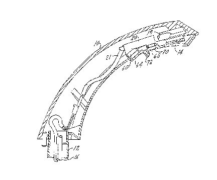
Fig. 1 is a side view, in part section, showing the principal components of an
electronically operated faucet;
Fig. 2 is an enlarged vertical section through the sensor assembly of Fig. 1;
Fig. 3 is a section along plane 3-3 of Fig. 2;
Fig. 4 is a top view of the base of the sensor assembly;
2

CA 02290079 1999-11-19
Fig. 5 is a section along plane 5-5 of Fig. 4; and
Fig. 6 is a section along plane 6-6 of Fig. 4.
DESCRIPTION OF THE PREFERRED EMBODIMENT
Electronically operated faucets are commonly found in commercial
S washrooms. Customarily, a user will place his hands beneath the faucet,
which will cause a
light beam, for example infrared, to be reflected from the transmitter to the
receiver, both
located on the underside of the faucet. Such reflection will provide a signal
which will
operate a valve, normally a solenoid, to start the flow of water through the
faucet. Usually
the faucet will be operated for a predetermined period of time.
This type of environment presents certain hazards to continued and successful
operation of the electronic controls for the faucet. There is both the flow of
water through
the faucet spout in which the electronic assembly is located and there is also
the inherent
danger from water being splashed upwardly from the sink or the hands of the
user into the
electronics which could provide a short circuit and a consequent malfunction.
Thus, it is
necessary to insure that the sensor control assembly is completely waterproof
and is not
susceptible to water either from within the faucet or from directly outside of
the faucet spout.
The present invention is directed to that end.
In Fig. l, the faucet spout housing is indicated at 10 and the spout housing
will be mounted on an upstanding mounting member 12. There is a faucet
discharge
indicated at 14. Normally, there will be a water conduit inside of the housing
10 which will
direct water to the discharge 14. The inlet end of this conduit is indicated
at 16 and the
outlet end is indicated at 18, all in Fig. 1.
3

CA 02290079 1999-11-19
The electronic sensor control assembly is indicated at 20 and is connected by
a
wires assembly 21, which contains the control wire for the transmitter and
receiver. The
control wires will then be connected to suitable components, for example a
solenoid and
power supply, to operate the valve controlling the flow of water through the
spout.
Fig. 2 illustrates the control assembly 20. There is a base 22 which has end
walls 24 and 26 and side walls 28 and 30. The base has an outwardly extending
bracket 32,
shown particularly in Figs. 3 and 4, which is used to attach the control
assembly to the
faucet spout housing 10. A screw for use in this attachment is illustrated at
34. The base 22
further has a bottom wall 36 which has an opening 38 providing access to the
LED 40
functioning as the transmitter and an opening 42 providing access to the LED
44 functioning
as the receiver. The bottom of the base 22 further has an upstanding
longitudinally
extending rib 46 which divides the channel 48 formed between the side walls 28
and 30 into
two areas thereby providing a means for isolating the lead wires running to
the transmitter
and receiver.
The base 22 further has a boss 50 integrally formed with end wall 26, which
end wall has a small slot 52. The combination of the boss and the slot 52 in
the end wall 26
provide a strain relief for the electrical wires extending from the conduit 21
and into the area
of the base 22. The wire pairs are identified at 54 and 56 in Fig. 2 and are
shown in more
detail in Fig. 3.
The LED 40 extends into a recess 58 in the bottom 36 of the base 22.
Surrounding the LED 40 is an annular seal member 60 which extends
circumferentially about
the LED 40 and provides a watertight seal between the area outside of the LED
and the
4

CA 02290079 1999-11-19
interior of the base 22. The bottom 36 of the base may have an undercut at 62
so that the
seal may be snapped in place and held about the LED during assembly. There is
a lens 64
which surrounds both the LED and the seal, with the lens being retained in a
bottom portion
66 of the faucet spout housing 10.
The mounting for the LED 44 is essentially the same as the mounting for LED
40, the only difference being the size of the components. There is a seal 68
and a lens 70,
with these elements performing the same function as they do in connection with
LED 40.
The bottom of the spout housing 10 may have a downwardly extending
projection 72 which functions to isolate the transmitter and receiver such
that no light can be
passed directly fberebefween. This eliminates false readings at the receiver
and insures that
any energy which is received by the receiver in fact is reflected by an object
below the
transmitter.
After the elements described have been assembled in the base 22, a suitable
potting compound 80, for example an epoxy, will fill the channel 48 extending
between the
side and end walls of the base. This epoxy will completely waterproof the
electrical
connections between the wires 54 and 56, each of which contains two
independent leads, as
particularly shown in Fig. 3. These leads will be directly connected to the
contacts 74 of the
LEDs, although such direct connection is not shown. Further, the
longitudinally extending
rib 46 will separate the lead wires and the electrical connections, preventing
any short circuit
between the wire pairs connected to the transmitter and to the receiver. The
potting
compound will flow down through the openings 38 and 42 so that the waterproof
material
will flow to the back of the LED to completely encapsulate the leads. This
eliminates any
5

CA 02290079 1999-11-19
potential for moisture reaching any portion of the electrical circuit.
In prior electronic faucets there was normally a printed circuit board located
within the faucet spout housing. The inclusion of a PC board at this location
caused severe
problems with moisture. The present invention eliminates the need for a PC
board, as there
is direct connection to the LEDs, with the direct connecting wires passing out
of the faucet
spout to the appropriate control elements. The wires are isolated one from
another by the
use of a rib and waterproofing is provided by the inclusion of a potting
compound which
completely surrounds the LEDs at the point of electrical connection, as well
as the wires
connected to the LEDs. To further waterproof the device, there is a seal at
the output side
of each LED, thus eliminating the potential for moisture from beneath the
faucet spout
reaching the electrical areas of the control assembly.
Whereas the preferred form of the invention has been shown and described
herein, it should be realized that there may be many modifications,
substitutions and
alterations thereto.
6

Representative Drawing
A single figure which represents the drawing illustrating the invention.
Administrative Status

2024-08-01:As part of the Next Generation Patents (NGP) transition, the Canadian Patents Database (CPD) now contains a more detailed Event History, which replicates the Event Log of our new back-office solution.

Please note that "Inactive:" events refers to events no longer in use in our new back-office solution.

For a clearer understanding of the status of the application/patent presented on this page, the site Disclaimer , as well as the definitions for Patent , Event History , Maintenance Fee  and Payment History  should be consulted.

Event History

Description Date
Time Limit for Reversal Expired 2018-11-19
Letter Sent 2017-11-20
Inactive: IPC from MCD 2006-03-12
Grant by Issuance 2003-08-05
Inactive: Cover page published 2003-08-04
Inactive: Final fee received 2003-05-15
Pre-grant 2003-05-15
Notice of Allowance is Issued 2003-04-16
Letter Sent 2003-04-16
Notice of Allowance is Issued 2003-04-16
Inactive: Approved for allowance (AFA) 2003-03-17
Amendment Received - Voluntary Amendment 2003-02-07
Amendment Received - Voluntary Amendment 2002-07-29
Letter Sent 2000-11-09
Request for Examination Requirements Determined Compliant 2000-10-18
All Requirements for Examination Determined Compliant 2000-10-18
Request for Examination Received 2000-10-18
Application Published (Open to Public Inspection) 2000-05-24
Inactive: Cover page published 2000-05-23
Inactive: IPC assigned 2000-01-31
Inactive: First IPC assigned 2000-01-31
Inactive: Filing certificate - No RFE (English) 1999-12-20
Letter Sent 1999-12-20
Application Received - Regular National 1999-12-14

Abandonment History

There is no abandonment history.

Maintenance Fee

The last payment was received on 2002-10-25

Note : If the full payment has not been received on or before the date indicated, a further fee may be required which may be one of the following

  • the reinstatement fee;
  • the late payment fee; or
  • additional fee to reverse deemed expiry.

Patent fees are adjusted on the 1st of January every year. The amounts above are the current amounts if received by December 31 of the current year.
Please refer to the CIPO Patent Fees web page to see all current fee amounts.

Owners on Record

Note: Records showing the ownership history in alphabetical order.

Current Owners on Record
SLOAN VALVE COMPANY
Past Owners on Record
MARTIN E. MARCICHOW
STEVEN R. OLIVER
Past Owners that do not appear in the "Owners on Record" listing will appear in other documentation within the application.
Documents

To view selected files, please enter reCAPTCHA code :


To view images, click a link in the Document Description column (Temporarily unavailable). To download the documents, select one or more checkboxes in the first column and then click the "Download Selected in PDF format (Zip Archive)" or the "Download Selected as Single PDF" button.

List of published and non-published patent-specific documents on the CPD .

If you have any difficulty accessing content, you can call the Client Service Centre at 1-866-997-1936 or send them an e-mail at CIPO Client Service Centre.

({010=All Documents, 020=As Filed, 030=As Open to Public Inspection, 040=At Issuance, 050=Examination, 060=Incoming Correspondence, 070=Miscellaneous, 080=Outgoing Correspondence, 090=Payment})


Document
Description 
Date
(yyyy-mm-dd) 
Number of pages   Size of Image (KB) 
Description 1999-11-18 6 230
Claims 1999-11-18 3 68
Abstract 1999-11-18 1 24
Drawings 1999-11-18 2 86
Claims 2002-03-15 3 74
Representative drawing 2000-05-14 1 11
Courtesy - Certificate of registration (related document(s)) 1999-12-19 1 115
Filing Certificate (English) 1999-12-19 1 164
Acknowledgement of Request for Examination 2000-11-08 1 180
Reminder of maintenance fee due 2001-07-22 1 112
Commissioner's Notice - Application Found Allowable 2003-04-15 1 160
Maintenance Fee Notice 2018-01-01 1 180
Correspondence 2003-05-14 1 38