Note: Descriptions are shown in the official language in which they were submitted.
CA 02290190 1999-11-19
LUMBER SPACING BOARD CONVEYOR METER
Field of the Invention
This invention relates to an apparatus for holding and conveying spacing
boards
to a board placer in a sawmill, and in particular relates to an apparatus
capable of automatically
metering spacing boards on a conveyor, for uniform delivery to a board
allocator for allocating
spacing boards for subsequent delivery and placing between tiers in a lumber
stack being formed
by a stacker in a sawmill.
Background of the Invention
Previously automatic board conveyors incorporated a board un-loading area. The
boards were un-loaded onto a chain conveyor by a transportable board bunk. The
board bunk was
typically placed by a forklift on to the top of a hoist raised above the board
conveyor. The hoist
was then lowered and the boards set down onto the chain conveyor. Once the
bunk was lowered
completely below the conveyor, the conveyor began to move the boards to an
unscrambles. The
unscrambles separated, the boards into a mat of adjacent boards lying on their
sides. The mat was
then translated to a board allocator. The allocator separated and allocated
the boards for timed and
2 0 sequenced delivery to an automatic board placer.
In this form of prior art system, the boards often arrive bunched up at the
unscrambles and need to be manually prodded and straightened in order for even
delivery to the
allocator by the board unscrambles.
It is therefore an object of the present invention to produce a board metering
apparatus wherein the delivery of boards is automatically controlled on the
board transfer for even
delivery of boards to the board unscrambles.
1
CA 02290190 1999-11-19
It is another object of the invention to produce a board transfer metering
apparatus
that can be retrofitted to existing board transferring systems.
Summary of the Invention
The term "boards" as used herein is intended to encompass sticks and dimension
lumber. Boards are loaded onto a chain conveyor by a transportable board bunk.
The board bunk
is placed on to the top of a scissor hoist which has been elevated between a
parallel pair of chains
comprising the upstream end of chain conveyor. The hoist is lowered to rest
the boards on the
chain conveyor. The bunk is lowered completely below the board conveyor to
release the boards
free of the bunk uprights onto the board conveyor.
A pair of rigid translatable board gates, one upstream and one spaced and
parallel
downstream, are mounted below and between the pair of conveyor chains. The
board gates can
be selectively elevated so as to extend into the flow path of the boards so as
to block flow of the
boards downstream on the conveyor. The gates may be retracted down out of the
board flow path.
Alternating sequential extension and retraction of the two gates meters the
flow downstream of
the boards bunched on the chain conveyor following removal from the board
bunk.
After the board bunk has been fully retracted down releasing the boards into a
pile
on top of the chain conveyor, the chain conveyor starts up momentarily moving
or jogging for a
short period the board pile up towards and against the first board meter gate
in its elevated
position. The first board gate is elevated so as to assist in straightening
any boards that might have
2 5 become skewed as the boards spill from the bunks onto the conveyor. To
begin metering the flow
of boards, the second, i.e. downstream, gate is raised. The first board gate
is then lower, allowing
the boards which were bunched up against it to tumble down against the second
gate. After a brief
pause (approximately 2 seconds) the first gate is elevated pushing its way up
through the shallow
2
CA 02290190 1999-11-19
downstream portion of the pile of boards, that is, up through the boards which
had tumbled down.
Elevating the first gate gently lifts, separates, and straightens the boards
so that a shallow layer,
bunch or bundle of boards is contained between the two elevated gates, leaving
a deeper layer,
bunch, bundle or pile of boards upstream of the first gate. After another
brief pause
(approximately 2 seconds) the second gate lowers to a position below the board
conveyor chains.
The board conveyor chains then jog forward (approximately 2 seconds, equal to
approximately
2 feet of travel) advancing the shallow layer of boards toward the board
unscrambler, and causing
the deeper pile of boards upstream of the first gate to bunch or pile up
against the first gate as they
were at the beginning of the breakdown cycle.
Repeating this breakdown cycle produces a spaced apart series of shallow piles
of
boards, spaced apart downstream of the second gate, effectively creating a
continuous layer of
shallow piled boards on the board conveyor chains. Because the boards are
retained between and
against two elevated gates during a holding time pause in the breakdown cycle,
the boards in the
resulting shallow layer are essentially parallel as they travel to the
unscrambler.
A photo-eye may be located at the unscrambler trough at the bottom of the
unscrambler to detect the presence or absence of boards waiting to be
unscrambled. If no boards
are detected, the two gates and chain conveyor are cycled through the
breakdown cycle repetitively
2 0 until boards are detected in the unscrambler trough, at which time
translation of the board gates
and the chain transfer is stopped. Each time the photo-eye in the unscrambler
trough causes a
monitoring processor to call for more boards, the board chain conveyor
advances approximately
2 feet, depositing the corresponding volume of boards from the shallow layer
carried on the
conveyor into the unscrambler trough. Because the shallow layer of boards on
the board chain
2 5 conveyor is controlled by the board metering apparatus, the volume of
boards deposited into the
unscrambler trough is consequently controlled, allowing the unscrambler to
operate with an
optimal amount of boards in the unscrambler trough. As a result, the board
unscrambler operates
at peak efficiency, delivering an adequate and continuous supply of boards to
downstream board
3
CA 02290190 1999-11-19
placing equipment. The unscrambler lifts and separates boards from the
unscrambler trough, and
transfers the unscrambled boards to the unscrambler outfeed to form a mat for
allocation to the
board placer. The unscrambler stops and starts as required to maintain a
constant supply of boards
at the allocator.
In summary, the board metering device of the present invention is mountable
beneath a board conveyor, and includes an upstream gate and a downstream gate.
The
downstream gate is generally parallel to and spaced apart a first distance
from the upstream gate.
The upstream gate cooperates with a first actuator for vertical actuation of
the upstream gate
between an upstream elevated position and an upstream lowered position. The
downstream gate
cooperates with a second actuator for vertical actuation of the downstream
gate between a
downstream elevated position and a downstream lowered position. When in the
upstream and
downstream elevated positions, respectively, the upstream and downstream gates
intersect a board
flow path so as to interrupt a downstream flow of boards along the board flow
path on the board
conveyor. When in the upstream and downstream lowered positions, respectively,
the upstream
and downstream gates do not intersect the board flow path so as not to
interrupt the downstream
flow of boards along the board flow path on the board conveyor.
The upstream gate has an exposed vertical length which is exposed across the
said
2 0 board flow path when in the upstream elevated position. The exposed
vertical length is sufficient
to dam a pile of boards loaded onto the board conveyor from an upstream
reservoir of boards.
The first distance between the upstream and downstream gates is sufficient to
allow segregation, between the upstream and downstream gates, of a leading
portion of the pile
2 5 of boards.
The first and second actuators are selectively sequentially actuated by timing
and
actuating means. During a first breakdown cycle phase, the first actuator
elevates the upstream
4
CA 02290190 1999-11-19
gate into the upstream elevated position so as to accumulate the pile of
boards against the
upstream gate. During a second breakdown cycle phase, the first actuator
lowers the upstream
gate into the upstream lowered position and the second actuator elevates the
downstream gate into
the downstream elevated position so as to release the leading portion of the
pile of boards from
the remainder of the pile of boards into the segregation space between the
upstream and
downstream gates. During a third breakdown phase cycle phase, the first
actuator elevates the
upstream gate into the upstream elevated position and the second actuator
lowers the downstream
gate into the downstream lowered position, so as to segregate the leading
portion of the pile of
boards from the remainder of the pile of boards.
Advantageously, the device further includes a board conveyor controller for
selective stepped advancing of the board conveyor in a downstream direction.
The board
conveyor controller cooperates with the timing and actuating means for stepped
advancing in the
downstream direction of the leading portion of the pile of boards during the
third breakdown
cycle phase. The board conveyor controller selectively stops the stepped
advancing of the board
conveyor in the downstream direction during the second breakdown cycle phase.
In one aspect of the present invention, the first and second actuators are
chains and
the upstream and downstream gates are mounted, respectively, to the chains. It
is understood
2 0 however that this is not intended to be limiting, as other types of
selectively operable actuators
such as hydraulic cylinders, mechanically driven arms or linkages, or cams or
the like might be
employed within the scope of the invention.
In a further aspect, the upstream and downstream gates are parallel rigid
plates,
2 5 although this is not intended to be limiting as forks, screens or other
forms of board flow dams
might be employed within the scope of the invention.
5
CA 02290190 1999-11-19
Further advantageously, the board conveyor is a laterally spaced apart pair of
longitudinal conveyors, laterally spaced so as to lie on opposite lateral
sides of said upstream and
downstream gates. The board reservoir may be a board bunk selectively
elevatable between said
laterally spaced apart part of longitudinal conveyors.
The invention provides other advantages which will be made clear in the
description of the preferred embodiments.
Brief Description of the Drawings
The invention will be better understood by reference to the accompanying
drawings, wherein:
Figure 1 is a side elevation view according to a preferred embodiment of the
invention.
Figure 2 is an enlarged sectional partially cut-away side elevation view of
the
apparatus of Figure 1 showing the two metering gates in their elevated
position at the
commencement of the breakdown cycle.
Figure 3 is the side elevation view of Figure 2 showing the upstream board
gate in
its lowered position.
Figure 4 is the side elevation view of Figure 2 showing the upstream board
gate
2 5 returned to its elevated position segregating the downstream-most boards.
Figure 5 is the side elevation view of Figure 2 showing the downstream board
gate
in its lowered position and the segregated boards translated downstream.
6
CA 02290190 1999-11-19
Figure 6 is the side elevation view of Figure 2 showing the upstream board
gate
once again lowered.
Figure 7 is the side elevation view of Figure 2 showing the upstream board
gate
once again elevated to segregate a second portion of boards.
Figure 8 is the side elevation view of Figure 2 showing the downstream board
gate
once again lowered and the segregated second portion of boards translated
downstream.
Figure 9 is the side elevation view of Figure 2 showing both board gates once
again elevated prior to segregating a third portion of boards.
Figure 10 is the plan view according to the preferred embodiment of Figure 1.
Figure 11 is the side elevation view of Figure 1 showing the first load of
boards
being broken-down and a second load of boards held in the board bunk.
Detailed Description of the Preferred Embodiment
Referring to the drawing figures wherein similar characters of reference
represent
corresponding parts in each of several views, the apparatus is generally
indicated by the reference
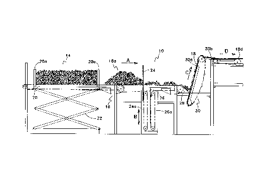
numeral 10 and is best seen in Figures 1 and 6. The apparatus 10 includes a
support frame
constructed of various vertical and horizontal structural supports 12.
Apparatus 10 is mounted
2 5 adjacent to a board placer allocator (not shown) upstream relative to the
direction of flow of
boards.
7
CA 02290190 1999-11-19
In the preferred embodiment as is best seen in Figure 1, the automatic board
delivery system consists first of a board bunk receiving area 14. A chain
conveyor 16 moves in
direction A. It is understood that chain conveyor 16 may be a longitudinal
series, or at least more
than one, chain conveyor. Boards 18 are loaded onto chain conveyor 16 by a
transportable board
bunk 20. Boards 18 are retained on board bunk 20 between bunk uprights 20a.
Board bunk 20
is placed on to the top of a scissor hoist 22 which has been elevated up
between a laterally spaced
apart pair of chain conveyors 16a seen better in Figure 10. Hoist 22 is
lowered to thereby lower
board bunk 20. Boards 18 protrude beyond the lateral edges of board bunk 20 so
that as the bunk
is lowered boards 18 are left resting on chain conveyor chains 16a. As board
bunk 20 is lowered
completely below chain conveyors 16a, boards 18 are released by bunk uprights
20a onto chain
conveyor 16. Chain conveyor 16 begins to translate boards 18 toward board
meter gates 24 and
26.
As seen in Figures 1 and 10 a pair of vertically selectively translatable
board meter
gates 24 and 26 are mounted below and between conveyor chains 16a. Board gates
24 and 26 are
generally planar rigid members, for example, rectangular plates which extend
and retract in
direction B into and out of the board flow path so as to meter the flow of the
bunched boards 18
on chain conveyor 16. Board gates 24 and 26 are extended and retracted by
chain drives 24a and
26a. Chain drives 24a and 26a are actuated by reversible drive motors (not
shown).
An unscrambler trough 28 is located downstream of conveyor 16, at the bottom
of
an unscrambler 30. Unscrambler 30 has lugs 30a for lifting and separating
boards 18 from
unscrambler trough 28. Unscrambler 30 transfers boards 16 to the unscrambler
outfeed 30b.
Boards 18 are translated on outfeed 30b into edge abutment with each other,
edge to edge, so as
2 5 to form a mat 18d for downstream allocation to the board placer (not
shown).
Advantageously, a photo-eye (not shown) is provided at trough 28 to detect the
presence or absence of boards 18. Based on the presence or absence of boards
18 in trough 28,
8
CA 02290190 1999-11-19
a controller activates or deactivates the unscrambler so as to better provide
a steady supply of
boards to the allocator .
In operation, the board metering apparatus 10 and board conveyor 16 remain at
rest
as shown in Figure 1 until a supply of boards 18 in the unscrambler trough 28
are depleted. Once
depleted, unscrambler photo-eye generates a signal to initiate a metering
cycle described below
as best shown in Figures 2 through S. After board bunk 20 has been fully
retracted, that is,
lowered, and has consequently released boards 18 as a board bunch 18a on top
of conveyor chains
16a, rotation of endless chain conveyor 16 is initiated, translating board
bunch 18a downstream
in direction A towards a first board gate 24. First board gate 24 is in the
elevated position to
interrupt the downstream translation of board bunch 18a. Conveyor 16 runs
until board bunch 18a
begins to pile up against first board gate 24. The piling of boards against
gate 24 assists in
straightening any boards that were skewed from spilling from bunk uprights 20a
onto conveyor
16. The second gate 26 is also initially raised as shown in Figure 2. First
board gate 24 is then
lowered as shown in Figure 3. After a brief time delay, (for example,
approximately 2 seconds)
to allow piled up board bunch 18a to flow against second gate 26, first gate
24 is again raised as
shown in Figure 4. Second gate 26 is then lowered, and chain conveyor 16
jogged downstream
for approximately 2 seconds, (equal to approximately 2 feet of travel). This
causes board bunch
18a to translate up to, or against, first board gate 24. Simultaneously, small
board bunch 18b is
2 0 translated downstream away from first gate 24, toward unscrambler trough
28 as shown in Figure
5.
After approximately 2 seconds, equal to approximately 2 feet of travel chain
conveyor 16 is again paused, at which time gate 24 is lowered and gate 26
raised to allow the
2 5 remaining board bunch 18a to slump against gate 26 as seen in Figure 6.
Gate 24 is then raised
to isolate the next small board bunch 18c between board gates 24 and 25 as
seen in Figure 7.
9
CA 02290190 1999-11-19
Board gate 26 is then lowered, and chain conveyor 16 again jogged to advance
small board bunch 18c downstream and to advance board bunch 18b in to
unscrambler trough 28
as seen in Figure 8. Gate 26 is once again elevated, as seen in Figure 9, to
continue the breakdown
cycle for the breakdown of board bunch 18a into smaller bunches carried into
trough 28. The
reader will notice the similarity in the gate positions in Figures 5 and 8 and
readily appreciate how
the alternating of elevating lowering of gates 24 and 26 allow for the
segregation of small bundles
of boards from the large bunch held on conveyor 16 and for their controlled
and timed sequential
release from between the gates onto the conveyor that steps or jogs the small
bundles towards, and
into, the holding trough 28 feeding the unscrambler 30.
It has been found advantageous to conduct the breakdown cycle in periodic
steps
of 2 seconds per step. It is understood however that this is not intended to
be limiting as
depending on the speed of the unscrambler, the timing of the periodic
breakdown steps may be
varied to provide a timely supply of small bunches or a shallow layer of
boards to the unscrambler
as boards will tend to spread out in actual anticipated operation of the
present device. Once
unscrambler lugs 30a lift and separate boards 18 from board trough 28, the
boards move onto
unscrambler outfeed 30b and form mat 18d. Mat 18d is conveyed downstream to
supply the board
allocator.
2 0 As will be apparent to those skilled in the art in the light of the
foregoing
disclosure, many alterations and modifications are possible in the practice of
this invention
without departing from the spirit or scope thereof. Accordingly, the scope of
the invention is to
be construed in accordance with the substance defined by the following claims.