Note: Descriptions are shown in the official language in which they were submitted.
CA 02290474 1999-11-15
SPECIFICATION
STRUCTURE FOR FITTING ROTARY DISPLACEMENT SENSOR
TECHNICAL FIELD
The present invention relates to an installation
structure for a rotation sensor for detecting rotation of a
rotating shaft such as a kingpin in vehicles.
BACKGROUND ART
Generally, in forklifts, pivoting of a rear axle is
limited so that the vehicle body does not incline excessively
from centrifugal force when turning. The pivoting of the
rear axle is controlled according to, for example, the
velocity of the vehicle and the steering angle. Japanese
Examined Patent Publication No. 4-24270 describes a method
for detecting the steering angle. In this publication, a
displacement sensor attached to a steering cylinder detects
the piston displacement, and the steering angle is calculated
from the displacement. However, using this method, it is
difficult to obtain the steering angle. Therefore, the
present applicant devised a potentiometer located on an upper
bracket of an axle beam for detecting the pivoting angle of a
kingpin and for obtaining the steering angle from the
detected pivoting angle.
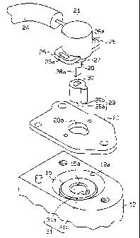
As shown in Fig. 21, a potentiometer 52 for detecting
the rotation of the kingpin 10 is mounted on the upper
bracket 51 supporting a kingpin 50 in a rear axle beam. The
potentiometer 52 is fixed to the upper bracket 51 through a
sensor support plate 54 so that the potentiometer 52 is
located above a bearing hole 53 in which the kingpin 50 is
-1-
CA 02290474 1999-11-15
supported. The potentiometer 52 is fixed to the support
plate 54 by screws (not shown), and the support plate 54 is
fixed to an upper bracket 51 by bolts (not shown). An input
shaft 55 of the potentiometer 52 passes through the through
hole 54a toward the kingpin 50, and a body 56 of the
potentiometer 52 is fixed to the support plate 54. The axis
of the input shaft 55 is aligned with the axis of the kingpin
50. A coupling portion 55a, the cross section of which is D-
shaped, is formed at the distal end of the input shaft 55,
and the coupling portion engages a D-shaped coupling hole 57
in the upper end of the kingpin 50. This prevents relative
rotation between the input shaft 55 and the kingpin 50.
Actually, dimensional inaccuracy of parts can occur,
and this may offset the axis of the input shaft 55 from the
axis of the kingpin 50. Roller bearings wear after a long
period of use, and this may cause the axis of the kingpin 50
to shift from the original position at the center of the
bearing hole 53. This may also result in offsetting the axis
of the input shaft 55 from the axis of the kingpin 50. As a
result, a radial force is applied from the kingpin 50 to the
input shaft 55, which may degrade the detection sensitivity
and durability of the potentiometer.52. If the radial force
becomes excessive, the potentiometer 52 may be damaged.
It is possible to prevent the input shaft 55 from
receiving the radial force from the kingpin 50 by providing a
clearance between the kingpin 50 and the input shaft _'i5.
However, this may cause slack between the input shaft 55 and
the kingpin 50 in the rotational direction and may degrade
detection sensitivity.
An objective of the present invention is to provide an
installation structure for a rotation detector that prevents
-2-
CA 02290474 1999-11-15
application of a radial force to an input shaft and slack
between a rotational shaft and the input shaft, thus
improving durability and detection sensitivity of the
rotation detector.
DISCLOSURE OF THE INVENTION
To achieve the objective, the present invention
provides an installation structure for a rotation detector,
wherein the rotation detector is fixed to a support member
supporting the rotational shaft such that an input shaft of
the rotation detector is coupled to and does not rotate with
respect to the rotational shaft and such that the axis of the
input shaft is substantially aligned with the axis of the
rotational shaft. The installation structure is
characterized in that the input shaft is coupled to the
rotational shaft through a rotation transmitter that permits
misalignment of the axis of the input shaft from the axis of
the rotational shaft by elastic deformation while limiting
relative rotation of the input shaft with respect to the
rotational shaft.
In this structure, the input .haft of the rotation
detector is coupled to the rotational shaft through the
rotation transmitter such that relative rotation of the input
shaft with respect to the rotational shaft is prevented and
the axis of the input shaft is substantially aligned with the
axis of the rotational shaft. When the axis of the input
shaft is offset from the axis of the rotational shaft, the
rotation transmitter is elastically deformed, which permits
the misalignment while limiting relative rotation between the
input shaft and the rotational shaft. Accordingly, when the
axis of the input shaft is offset from the axis of the
rotational shaft, radial force applied from the rotational
-3-
CA 02290474 1999-11-15
shaft to the input shaft is absorbed and reduced, and the
rotation of the rotational shaft is transmitted to the input
shaft. This prevents wear and damage caused by radial force
and also prevents slack between the input shaft and the
rotational shaft in the rotational direction, which improves
detection accuracy.
The rotation transmitter includes a coupling recess
located at an end of either the rotational shaft or the input
shaft, and a coupling shaft is located at an end of the other
shaft. The coupling shaft is placed in the coupling recess,
and an elastic coupler that elastically couples the coupling
recess with the coupling shaft connects the two together.
In this structure, the elastic coupler, which couples
the coupling recess, which is located in one end of the
rotational shaft or the input shaft, with the coupling shaft,
which is located at an end of the other shaft, permits
misalignment of the coupling recess from the coupling shaft
and limits relative rotation of the coupling recess to the
coupling shaft. This simplifies the structure and reduces
the number of parts and installation steps.
In another structure, the elastic coupler includes an
engaging portion that integrally rotates with the coupling
recess and an elastic member having a fitting portion in
which the coupling shaft is inserted to integrally rotate
with the elastic member.
In this structure, the elastic member is coupled to the
coupling recess to integrally rotate with the coupling recess
by engaging the engaging portion of the elastic member with
the coupling recess. Similarly, the elastic member is
coupled to the coupling shaft to integrally rotate wit=h the
-4-
CA 02290474 1999-11-15
coupling shaft by inserting the coupling shaft in the fitting
portion of the elastic member. Accordingly, the elastic
member, which engages the coupling shaft and the coupling
recess, respectively, to integrally rotate with them, limits
relative rotation between the input shaft and the rotational
shaft and permits misalignment of their axes by elastic
deformation. The elastic coupler is made of elastic material
that is easy to form.
The coupling recess may be located in the end of the
rotational shaft, and the coupling shaft may be located at
the end of the input shaft. In this case, the coupling shaft
and the coupling recess are easily machined.
In another structure, the coupling recess includes
first and second columnar holes. The first columnar hole is
coaxial with the rotational shaft, and the axis of the second
columnar hole is parallel to the axis of the first columnar
hole. The engaging portion of the elastic member includes a
first body corresponding to the first hole and a second body
corresponding to the second hole. In this case, the coupling
recess stops relative rotation. Only one drilling is
necessary for forming each of the first and second holes,
which reduces time spent for machining the coupling recess.
The cross section of the coupling shaft may be D-shaped,
and the fitting portion of the elastic member may be a D-
shaped engaging hole that passes through the first body. In
this case, an existing rotation detector, the coupling shaft
of which has a D-shaped cross section, can be used.
When the elastic member is made of synthetic rubber,
formation of the elastic member is easier.
-5-
CA 02290474 1999-11-15
In another structure, a tapered portion for guiding the
elastic member into the coupling recess is provided on one of
the opening end of the coupling recess and the lower end of
the elastic member. In this structure, when the elastic
member is fitted into the coupling recess, the tapered
portion guides the elastic member into the coupling recess.
Accordingly, the elastic member is more easily fitted :in the
coupling recess.
In another structure, the elastic coupler is made of
rubber and includes a body and a fitting portion. The body
fits in and integrally rotates with the coupling recess of
the rotational shaft. The fitting portion receives and
integrally rotates with the coupling shaft. The fitting
portion has a deformation preventing member on the inner
surface of a hole in the body. The deformation preventing
member is cylindrical with a slit and is made of a plate of
hard material.
In this structure, since the deformation preventing
member is attached to the rubber of the body by fusion, the
torque transmitted from the elastic coupler to the input
shaft is received over an entire contact surface, which
reduces the deformation of the rubber from torsion.
Accordingly, when the direction of rotation is frequently
changed, the durability of the elastic coupler is improved.
The deformation preventing member may be made of a
stainless steel plate and may be integrally molded with the
body by insert molding. In this case, there is no need to
attach the deformation preventing member to the body later,
and the member is rustproof and durable.
In another structure, the elastic coupler is a spring.
-6-
CA 02290474 1999-11-15
The ends of the spring are supported by the rotational shaft
to extend in parallel with a plane including the axis of the
rotational shaft in the coupling recess and is coupled to the
coupling shaft to relatively move in a direction of the line
connecting the ends.
In this structure, the spring, in the coupling recess,
extends in a direction parallel to a plane that includes the
axis of the rotational shaft and limits relative rotation
between the rotational shaft and the coupling shaft. When
the axis of the rotational shaft is misaligned with the axis
of the coupling shaft in the longitudinal direction of the
spring, the misalignment is permitted by the relative
movement between the spring and the coupling shaft. When,
misalignment of the axes occurs in a direction angular to the
longitudinal direction of the spring, the misalignment is
permitted by the elastic deformation of the spring.
Accordingly, the durability of the elastic coupler improves
compared to one made of rubber.
In another structure, the spring is angular to the axis
of the rotational shaft and is inserted in an inserting
portion formed in the coupling shaft. In this case, the
spring is received in the inserting portion, thus ensuring
the coupling of the spring to the coupling shaft.
In another structure, the inserting portion is a
through hole formed in the coupling shaft, and the spring is
supported by a pair of engaging grooves formed in the
rotational shaft. In this structure, during installation,
the coupling shaft is moved toward the engaging grooves with
the spring inserted in the through hole of the coupling shaft.
Then, the spring engages the engaging grooves. Accordingly,
the spring is easily replaced.
CA 02290474 1999-11-15
When there is one spring, the number of parts is not
increased.
In another structure, a pair of the springs are
provided. The coupling shaft is held between a rotation
stopping portion to prevent rotation. This facilitates
machining the input shaft.
The spring may be supported by a pair of engaging holes
respectively formed in the rotational shaft.
Also, the spring may be supported by a pair of engaging
grooves respectively formed in the rotational shaft. =Cn this
case, the spring is more easily replaced compared to the
structure in which the spring is supported by the engaging
holes.
In another structure, the rotation stopping portion
formed in the coupling shaft of the input shaft is held
between the springs to prevent the rotation. In this case,
an existing potentiometer can be used as a rotation detector.
Bar springs or leaf springs are used as the springs.
When a leaf spring is used, the spring force is easily
altered by changing the spring.
In another structure, the rotational shaft is a kingpin,
which is provided in the rear axle beam of the forklift to
support the steered wheels.
In this structure, the rotation detector is provided in
the rear axle beam of the forklift to detect the rotation
amount of the kingpin. A radial force applied to the input
_g_
CA 02290474 1999-11-15
shaft of the rotation detector from the kingpin does not
shorten the life of the potentiometer. Slack between the
kingpin and the input shaft is prevented, which improves the
accuracy of detection.
BRIEF DESCRIPTION OF THE DRAWINGS
Fig. 1 is an exploded perspective view showing the
installation structure of a potentiometer according to a
first embodiment of the present invention.
Fig. 2 is a plan view showing steered wheels supported
by a rear axle beam of a forklift.
Fig. 3 is a partial cross sectional view of the rear
axle beam.
Fig. 4 is a partial cross sectional view showing the
installation structure of the potentiometer.
Fig. 5 is a plan view of a kingpin.
Fig. 6 is a partial exploded perspective view showing
the installation structure of a potentiometer according to a
second embodiment.
Fig. 7 is a partial cross sectional view showing the
installation structure of the potentiometer.
Fig. 8 is a plan view of a kingpin.
Fig. 9 is a partial exploded perspective view showing
the installation structure of a potentiometer of a third
_g_
CA 02290474 1999-11-15
embodiment.
Fig. 10 is a partial cross sectional view showing the
installation structure of the potentiometer.
Fig. 11 is a plan view of a kingpin.
Fig. 12 is a partial exploded perspective view showing
the installation structure of a potentiometer according to a
fourth embodiment.
Fig. 13 is a plan view of a kingpin.
Fig. 14 is a partial cross sectional view showing the
installation structure of the potentiometer.
Fig. 15 is a perspective view of a deformation
preventing member that is used in a fifth embodiment.
Fig. 16 is a diagrammatic view showing an output shaft
and an elastic member.
Fig. 17 is a partial exploded, perspective view showing
the installation structure of a potentiometer according to a
fifth embodiment.
Fig. 18 is a partial exploded perspective view showing
the installation structure of a potentiometer according to
another example.
Fig. 19 is a partial exploded perspective view _showing
the installation structure of a potentiometer according to
another example.
-10-
CA 02290474 1999-11-15
Fig. 20 is a partial exploded perspective view showing
the installation structure of a potentiometer according to
another example.
Fig. 21 is a partial exploded perspective view showing
the installation structure of a potentiometer according to a
prior art example.
BEST MODE FOR CARRYING OUT THE INVENTION
First Embodiment
An installation structure of a potentiometer for
detecting a kingpin of a rear axle beam of a forklift
according to a first embodiment of the present invention will
now be described with reference to Figs. 1-5.
As shown in Fig. 2, a bell crank 3 is rotatably
supported in a rear axle beam 1 of a forklift by a bell crank
pin 4. The bill crank 3 steers wheels 2 based on the
operation of the steering wheel (not shown). Steering
knuckles 7, 8 are provided at both ends of the rear axle beam
1 to support the wheels 2. The bell crank 3 is coupled to
the steering knuckles 7, 8 through a pair of steering rods 5,
6. A first end of the steering rod 5 is rotatably coupled to
the coupler pin 9a, which is secured to the bell crank 3. A
second end of the steering rod 5 is rotatably coupled to a
coupler pin 10a, which is secured to the steering knu~~kle 7.
A first end of the steering rod 6 is rotatably coupled to the
coupler pin 9b that is secured to the bell crank 3. A second
end of the steering rod 6 is rotatably coupled to a coupler
pin lOb that is secured to the steering knuckle 8.
Fig. 3 shows one of the wheels 2 supported by the rear
-11-
CA 02290474 1999-11-15
axle beam 1. An upper bracket 12, which is a support member,
is secured to an upper beam 11 of the rear axle beam 1, and a
lower bracket 14 is secured to a lower beam 13. A bearing
hole 12a vertically passes through the upper bracket 12, and
a bearing hole 14a vertically passes through the lower
bracket 14. A kingpin 15, which is a rotational shaft, is
rotatably supported in the bearing holes 12a, 14a through
needle bearings 16. The steering knuckle 7 is secured to and
integrally rotates with the kingpin 15. The wheels 2 <~re
rotatably supported by a shaft 17 of the steering knuckle 7
through tapered roller bearings 18, 19.
As shown in Fig. 3, a potentiometer 21, which is a
rotation detector, is installed on an upper surface 12b of
the upper bracket 12 through a sensor support plate 20. The
potentiometer 21 is fixed to the support plate 20 by screws
22. The support plate 20 is fixed to the upper surface 12b
of the upper bracket 12 by a bolt 23. A lead wire 24 is
connected to the potentiometer 21.
The support member 20 is, for example, a die-cast plate.
As shown in Figs. 1 and 4, an attachment hole 20a is formed
at the center of the support plate ~0.
As shown in Figs. 1 and 4, the potentiometer 21
includes a columnar body 25, attachments 26 located on both
sides of the body 25, a lower end 27 projecting from the
lower surface of the body 25, and an input shaft 28
projecting from the lower surface of the lower end 27. The
lower end 27 is placed in the attachment hole 20a. An
elongated hole 26a is formed in each attachment 26 so that
the body 25 is fixed on the support plate 20 by screws 22.
The distal end of the input shaft 28 includes a coupling
shaft 28a. In this embodiment, the cross section of i~he
-12-
CA 02290474 1999-11-15
coupling shaft 28a is D-shaped. A bushing 29, which is an
elastic coupler, or an elastic member, is fitted on the
coupling shaft 28a. The bushing 29 is, for example, made of
synthetic rubber. The columnar bushing includes a first body
(large radius body 29a) and a second body (small radius body
29b). The large radius body 29a is coaxial with the input
shaft 28, and the axis of the small radius body 29b is
parallel to the axis of the large radius body 29a. An
engaging hole 30 vertically passes through the center of the
large diameter body of the bushing 29. The engaging hole 30
receives the coupling shaft 28a. When the coupling shaft 28a
is engaged with the engaging hole 30, the large radius body
29a is coaxial with the input shaft 28. In this embodiment,
an engaging portion includes the large radius body 29a and
the small radius body 29b, and a fitting portion includes the
engaging hole 30.
A coupling hole 31, which is a coupling recess, is
formed in the upper end of the kingpin 15. The bushing 29
engages the coupling hole 31. The coupling hole 31 includes
a first columnar hole (large radius hole 31a) and a second
columnar hole (small radius hole 31). The large radius hole
is coaxial with the kingpin 15. The axis of the small radius
hole 31b is parallel to the axis of the large radius hole 31a.
The large radius body 29a engages the large radius hole 31a,
and the small radius body 29b engages the small radiu~~ hole
31b. A tapered portion 15a is formed at the opening of the
coupling hole 31.
As shown in Figs. 9 and 5, the potentiometer 21 is
coupled to the kingpin 15 through the bushing 29. The
bushing is attached to the input shaft 28 and fitted .in the
coupling hole 31. In this embodiment, the coupling shaft 28a,
the bushing 29 and the coupling hole 31 constitute a :rotation
-13-
CA 02290474 1999-11-15
transmitting means.
Operation of an installation structure of the above
rotation detector will now be described.
Since the coupling hole 31 is a combination of the
large radius hole and the small radius hole, the coupling
hole 31 is formed by one drilling for each hole 31a, 31b.
When installing the potentiometer 21 on the upper
bracket 12, the bushing 29 is attached to the coupling shaft
28a and is fitted in the coupling hole 31 through the
attachment hole 20a of the support plate 20. During the
installation, even when the axis of the input shaft 28 is
offset from the axis of the kingpin 15, the tapered portion
15a of the opening of the coupling hole 31 guides the bushing
29 into the coupling hole 31. As a result, the input shaft
28 is coupled to the kingpin 15 through the bushing 29 to
rotate integrally with the kingpin 15.
When the bell crank 3 is operated by the steering wheel
(not shown) after the installation of the potentiometer, the
steering knuckles 7,8 are operated through the steering rods
5, 6. The wheels 2 are steered by a steering angle based on
the rotation amount of the steering wheel. The rotation
amount of the kingpin 15 corresponds to the steering angle,
and the input shaft 28 rotates the same amount.
When the input shaft 28 is coaxial with the kingpin 15,
the kingpin 15 rotates without applying a bending moment to
the input shaft 28. The rotation of the kingpin 15 is
transmitted to the input shaft 28 through the bushing 29,
which rotates the input shaft 28 as much as the kingpin 15.
Then, the potentiometer 21 detects the rotational angle of
-14-
CA 02290474 1999-11-15
the kingpin 15 as the rotation amount.
When the axis of the input shaft 28 is offset from the
axis of the kingpin 15 because of dimensional inaccuracy or
displacement of the kingpin resulting from the wear of the
needle bearings 16, the bushing 29 elastically deforms and
allows misalignment between the input shaft 28 and the
kingpin 15. At this time, a radial force is applied to the
input shaft 28 from the kingpin 15 through the bushing 29.
Accordingly, the radial force applied to the input shaft is
absorbed by the elastic deformation of the bushing 29.
In this state, the rotation of the kingpin 15 is
transmitted to the input shaft 28 through the deformed
bushing 29. At this time, since there is no clearance
between the input shaft 28 and the kingpin 15, the rotation
of the kingpin 15 is transmitted to the input shaft 28
without any loss. Accordingly, the actual rotational angle
of the kingpin 15 is detected by the potentiometer 21.
This embodiment has the following advantages.
(1) The input shaft 28 is connected to the rotational
shaft (kingpin 15) by an elastic coupler (bushing 29), which
permits misalignment between the axis of the input shaft 28
and the axis of the rotational shaft due to its elastic
deformation and which limits relative rotation between the
input shaft 28 and the rotational shaft. Accordingly, when
the axis of the input shaft 28 is offset from the axi:~ of the
rotational shaft, the elastic deformation of the elastic
coupler absorbs the radial force applied to the input shaft
28 from the rotational shaft, and the rotation of the
rotational shaft is transmitted to the input shaft 28 without
loss. As a result, this prevents early wear and damage to
-15-
CA 02290474 1999-11-15
the rotation detector (potentiometer 21), which are caused by
radial force applied to the input shaft 28, and improves
detection accuracy by eliminating slack between the
rotational shaft and the input shaft 28 in the rotational
direction.
(2) The elastic member (bushing 29) is fixed to the
input shaft 28 and integrally rotates with the input shaft 28.
The elastic member is fitted in the coupling hole 31 in the
rotational shaft (kingpin 15), and relative rotation between
them is prevented. Accordingly, when the axis of the input
shaft 28 is misaligned with the axis of the rotational shaft,
elastic deformation of the elastic member permits
misalignment and limits the rotation relative to the
rotational shaft. Also, the elastic member is more easily
manufactured.
(3) The coupling shaft 28a of the input shaft 28
engages the engaging hole 30 of the elastic member (bushing
29), which limits relative rotation. The bushing 29 engages
the coupling hole 31 of the rotational shaft (kingpin 15),
which limits relative rotation. Accordingly, the relative
rotation between the input shaft 28.and the bushing 29 and
between the bushing 29 and the rotational shaft is
mechanically limited, which prevents relative rotation
between the rotational shaft and the input shaft. As a
result, the rotation of the rotational shaft is transmitted
without fail, which improves the reliability and accuracy of
the rotation detector.
(4) The coupling hole 31 and the coupling shaft 28a are
shaped to prevent rotation relative to the elastic member,
respectively. Accordingly, rotation of the rotationa7_ shaft
is transmitted to the input shaft 28 without attachment by
-16-
CA 02290474 1999-11-15
adhesive for a relatively long period.
(5) Since the bushing 29 is made of synthetic rubber,
it is easily formed.
(6) The coupling hole 31 is formed to include the
columnar large radius hole 31a and the columnar small radius
hole 31b. Accordingly, each hole 31a, 31b is formed by one
drilling, respectively, which reduces the time spent for
manufacturing the coupling hole 31.
(7) Since the tapered portion 15a is formed at the
opening edge of the coupling hole 31, the bushing 29 is
guided into the coupling hole 31 by the tapered portion 15a
when the axis of the input shaft is offset from the axis of
the kingpin 15. As a result, installation of the rotation
detector is rapid and simple.
Second Embodiment
A second embodiment of the present invention will now
be described with reference to Figs. 6-8. Since the second
embodiment is similar to the first embodiment, similar
structures are referred to with similar numerals and a
detailed description has been omitted. In Fig. 6, the upper
bracket 12 and the support plate 20 are not shown.
As shown in Figs. 6 and 7, an input shaft 28 of the
potentiometer 21 is different from that of the first
embodiment. The cross section of a coupling shaft 28a is
circular. A through hole 28b, which is an inserting portion,
is formed in the coupling shaft 28a to extend radially and to
intersect the axis of the coupling shaft 28a.
-17-
CA 02290474 1999-11-15
A coupling hole 32, which is a coupling recess, is
formed in the upper end of the kingpin 15. The input shaft
28 is arranged in the center of the coupling hole 32.
Engaging grooves 33a, 33b are to face one another across the
axis of the coupling hole 32. The engaging groove 33a is
aligned with the engaging groove 33b, and a tapered portion
15b is formed at the top end of each engaging groove 33a, 33b.
As shown in Fig. 8, a bar spring 34, which is an
elastic coupler and a spring member, is received in the
through hole 28b of the input shaft 28. Both ends of t:he bar
spring 34 are press fitted in the engaging grooves 33a, 33b.
The bar spring 34 is made of piano wire. In this embodiment,
the through hole 28b, the engaging grooves 33a, 33b, and the
bar spring 34 constitute a rotation transmitting means.
Operation of the installation structure of the
illustrated rotation detector will now be described.
Since the coupling hole 32 is columnar, the coupling
hole 32 is formed in the kingpin 15 by one step of drilling.
In the installation of the potentiometer 21 to the
upper bracket 12, the bar spring 34 that has been engaged
with the input shaft 28 through the through hole 28b is
engaged with the engaging grooves 33a, 33b of the kingpin 15.
In this way, the input shaft 28 is coupled to the kingpin 15
through the bar spring 34 to rotate integrally. Accordingly,
the potentiometer 21 is installed to the upper bracket: 12
after the bar spring 34 is engaged with the input shaft 28.
When the axis of the input shaft 28 is slightly offset. from
the axis of the kingpin 15 in the installation, the bar
spring 34 is guided by the tapered portion 15b into the
engaging grooves 33a, 33b, which facilitates installation.
-18-
CA 02290474 1999-11-15
When the input shaft 28 is coaxial with the kingpin 15,
the kingpin rotates without applying a bending moment to the
input shaft 28, and the rotation is transmitted to the input
shaft 28 through the bar spring 34. Accordingly, the
potentiometer 21 detects the rotational angle of the kingpin
15.
When the axis of the input shaft is offset from t=he
axis of the kingpin 15 in the longitudinal direction of the
bar spring 34, one of the input shaft 28 and the bar spring
34 moves in the longitudinal direction with respect to the
other, which permits misalignment between the input shaft and
the kingpin 15. When the axis of the input shaft is offset
from the axis of the kingpin 15 in a direction perpendicular
to the longitudinal direction of the bar spring 34, elastic
deformation of the bar spring 34 permits the misalignment
between the input shaft 28 and the kingpin 15. At this time,
a radial force is applied to the input shaft 28 from the
kingpin 15 thxough the bar spring 34. Accordingly, the
radial force applied to the input shaft 28 from the kingpin
15 is absorbed and mitigated by the elastic deformation of
the bar spring 34.
When the kingpin 15 rotates in this state, the rotation
of the kingpin 15 is transmitted to the input shaft 28
through the deformed bar spring 24. Since the bar sprang 34
engages the input shaft 28 and the kingpin 15, the rotation
of the kingpin 15 is transmitted to the input shaft without a
loss. Accordingly, the potentiometer 21 detects the actual
rotational angle of the kingpin 15.
The present embodiment has the following advantages.
-19-
CA 02290474 1999-11-15
(1) The input shaft 28 is coupled to the rotational
shaft (kingpin 15) by the elastic coupler (bar spring 34),
which permits the misalignment between the axis of the input
shaft 28 and the axis of the rotational shaft by its elastic
deformation and limits relative rotation between the input
shaft 28 and the rotational shaft. Accordingly, when the
axis of the input shaft 28 is offset from the axis of l~he
rotational shaft, the radial force applied to the inpul~ shaft
28 from the rotational shaft is absorbed, and rotation of the
rotational shaft is transmitted to the input shaft without a
loss. As a result, wear and damage to the rotation detector
are prevented, which improves the detection accuracy.
(2) The input shaft 28 is located in the coupling hole
32 formed in the rotational shaft (kingpin 15) and is coupled
to the center of the spring (bar spring 34) supported in the
coupling hole 32. The spring and the input shaft 28 move
relative to one another in the longitudinal direction of the
spring. Accordingly, since the spring is more durable than
an elastic member such as one made of synthetic rubber, the
coupling between the rotational shaft and the input shaft is
more reliable.
(3) The spring (bar spring 34) passes through the
inserting portion (through hole 28b). Accordingly, relative
rotation between the input shaft 28 and the rotational shaft
is more reliably limited. Only one bar spring 34 is used to
couple the input shaft 28 to the kingpin 15, which does not
increase the number of parts. Since the bar spring 34 is
engaged with the engaging grooves 33a, 33b, the bar spring 34
can be easily replaced.
(4) Since the bar spring 34 is made of piano wire and
-20-
CA 02290474 1999-11-15
has a long fatigue limit, it is not easily broken when a load
is continuously applied to the bar spring for a long period.
This increases the reliability of the bar spring 34. The bar
spring resists corrosion, which further increases the
reliability of the bar spring 34 against damage.
(5) The tapered portion 15b, which is formed at the
upper end of each engaging groove 33a, 33b, guides the bar
spring 34 into the engaging grooves 33a, 33b. This
facilitates installation of the rotation detector.
Third Embodiment
A third embodiment will now be described with reference
to Figs. 9-11. Since the structure of the potentiometer 21
of the third embodiment is similar to those of the first and
second embodiments, the same numerals are used for similar
structures, and a detailed description is omitted. In Fig. 9,
the upper bracket 12 and the support plate 20 are omitted.
As shown in Figs. 9 and 10, a coupling shaft 28a
similar to that of the first embodiment is formed on an input
shaft 28 of a potentiometer 21. That is, a rotation stopper
28c is formed on the coupling shaft 28a. The rotation
stopper 28c is formed by partially cutting away the column of
the coupling shaft 28a. A coupling hole 32 similar to that
of the second embodiment is formed in the upper end of the
kingpin 15. Instead of the engaging grooves 33a, 33b of the
second embodiment, pairs of engaging holes 35a, 35b and 36a,
36b are provided in the kingpin 15. The engaging holes 35a,
35b, which communicate the inner surface of the coupling hole
32 to the outer surface of the kingpin 15, are vertically
aligned and are parallel to a plane including the axis of the
kingpin 15. Also, a pair of engaging holes 36a, 36b are
-21-
CA 02290474 1999-11-15
aligned and are parallel to the engaging holes 35a, 35b.
As shown in Fig. 11, a bar spring 37a, which is an
elastic couplet and spring, is received in the pair of
engaging holes 35a, 35b of the kingpin 15. A bar spring 37b
is received in the 36a, 36b. Each bar spring 37a, 37b is
made of piano wire. The coupling shaft of the input shaft is
received between the bar springs 37a, 37b to prevent relative
rotation between the coupling shaft 28a of the input shaft 28
and the kingpin 15. In detail, the center portion of the bar
spring 37a is pressed against the planar rotation stopper 28c
of the coupling shaft 28a, and the center portion of the bar
spring 37b is pressed against the other side of the coupling
shaft 28a from the rotation stopper 28c. In this embodiment,
the coupling shaft 28a, the engaging holes 35a, 35b, 36a, 36b,
and the bar springs 37a, 37b constitute a rotation
transmitting means.
Operation of an installed rotation detector structure
will now be described.
When installing the potentiometer 21 on the upper
bracket 12, first, the bar springs ~7a, 37b are inserted in
the corresponding engaging holes 35a, 35b, 36a, 36b of the
kingpin 15. Then, the coupling shaft 28a is placed between
the bar springs 37a, 37b. This couples the input shaft. 28 to
the kingpin 15 so they integrally rotate with one another
through the bar springs 37a, 37b. When the input shaft. 28
and the kingpin 15 are coaxial, the kingpin 15 rotates
without applying a bending moment to the input shaft 28. The
rotation of the kingpin 15 is transmitted to the input shaft
28 through the bar springs 37a, 37b. Accordingly, the
potentiometer 21 detects the rotational angle of the kingpin
15.
-22-
CA 02290474 1999-11-15
When the axis of the input shaft 28 is offset from the
axis of the kingpin 15 in a longitudinal direction of the bar
springs 37a, 37b, misalignment between the input shaft 28 and
the kingpin 15 is permitted by the relative movement between
the input shaft 28 and the bar springs 37a, 37b. When the
axis of the input shaft 28 is offset from the axis of the
kingpin 15 in a direction angular to the longitudinal
direction of the bar springs 37a, 37b, the elastic
deformation of the bar springs 37a, 37b permits the
misalignment between the input shaft 28 and the kingpin 15.
A this time, a radial force is applied to the input shaft 28
from the kingpin 15 through the deformed bar springs 37a, 37b.
However, the radial force from the kingpin 15 to the input
shaft is absorbed and mitigated by the elastic deformation of
the bar springs 37a, 37b.
When the kingpin 15 rotates in this state, the rotation
of the kingpin 15 is transmitted to the input shaft 28
through the deformed bar springs 37a, 37b. Since the bar
springs 37a, 37b engage the kingpin 15 and grip the input
shaft 28, the rotation of the kingpin 15 is transmitted to
the input shaft 28 without loss. Accordingly, the actual
rotational angle of the kingpin 15 is detected by the
potentiometer 21.
The present embodiment has the following advantages.
(1) The input shaft 28 is coupled to the rotational
shaft (kingpin 15) by the elastic couplers (bar springs 37a,
37b), which permit misalignment between the axis of the input
shaft 28 and the axis of the rotational shaft by their
elastic deformation and limit relative rotation between the
input shaft and the rotational shaft. Accordingly, the
-23-
CA 02290474 1999-11-15
simple structure improves the durability and detection
accuracy of the rotation detector (potentiometer 21).
(2) As in the second embodiment, the input shaft 28 is
arranged in the coupling hole 32 formed in the rotational
shaft and is coupled to the center portion of the springs
(bar springs 37a, 37b) supported in the coupling hole 32.
The rotational shaft (kingpin 15) and the input shaft 28 move
in the longitudinal direction of the springs 37a, 37b
relative to one another. Since the elastic coupler is formed
by the springs 37a, 37b, which are more durable than the
rubber elastic members, the reliability is improved.
(3) The coupling shaft 28a of the input shaft 28 is
received between the pair of springs (bar springs 37a, 37b)
to prevent rotation. Since only the coupling shaft having
the rotation stopper 28c is formed, machining is simple.
Further, as long as the rotation stopper 28c is formed on the
input shaft 28 of the potentiometer 21, a potentiometer 21
that is currently on the market can be used.
(4) The coupling shaft 28a is received between the bar
springs 37a, 37b made of a piano wide. Accordingly, the
springs 37a, 37b are not easily damaged by continuous load
applied to them, which increases the reliability. Also, the
bar springs resist corrosion, which further increases the
reliability.
Fourth Embodiment
A fourth embodiment will now be described with
reference to Figs. 12-14. The differences of the fouri~h
embodiment from the third embodiment are engaging grooves 38a,
38b, 39a, 39b and leaf springs 40a, 40b, which correspond to
-24-
CA 02290474 1999-11-15
the engaging holes 35a, 35b, 36a, 36b, and the bar springs
37a, 37b of the third embodiment. Structures similar to
those of the third embodiment have the same reference
numerals and are not described in detail. Also, in Fig. 12,
the upper bracket 12 and the support plate 20 are not shown.
A tapered portion 28d is formed at the distal end of a
coupling shaft 28a of an input shaft 28. A pair of engaging
grooves 38a, 38b are formed at the opening rim of the
coupling hole 32 of the kingpin 15 to communicate the inner
wall of the coupling hole 32 to the outer wall of the kingpin
15. The engaging grooves 38a, 38b are horizontally aligned
and are parallel to a plane that includes the axis of the
kingpin 15. Also, a pair of engaging grooves 39a, 39b are
horizontally aligned and are parallel to the pair of the
engaging grooves 38a, 38b.
As shown in Fig. 13, a leaf spring 40a, which is an
elastic coupler and spring, is press fitted in the pair of
the engaging grooves 38a, 38b. Similarly, a leaf spring 40b
is press fitted in the pair of engaging grooves 39a, 39b. A
coupling shaft 28a is held between the leaf springs 40a, 40b.
In detail, a rotation stopper 28c o~ the coupling shaft 28a
is pressed against the center portion of the leaf spring 40a,
and the center portion of the leaf spring 40b is pressed
against the other side of the coupling shaft 28a from the
rotation stopper 28c.
In the present embodiment, the coupling shaft 28a, the
engaging grooves 38a, 38b, 39a, 39b, and the leaf springs 40a,
40b constitute a rotation transmitting means.
The installation structure as described above has
operation substantially similar to that of the third
-25-
CA 02290474 1999-11-15
embodiment.
Accordingly, the present embodiment has the following
advantages in addition to the advantages (1)-(3) of thE: third
embodiments.
(1) Since the coupling shaft 28a is held between the
leaf springs 40a, 40b, the forces of the springs are easily
adjusted by varying the width of the springs without changing
the thickness of the springs. Accordingly, the spring force
is easily determined only by the spring member without
changing the engaging grooves 38a, 38b, 39a, 39b.
(2) When the axis of the input shaft 28 is slightly
offset from the axis of the kingpin 15, the tapered portion
28d formed at the lower end of the coupling shaft 28a <guides
the coupling shaft 28a between the leaf springs 40a, 40b.
Fifth Embodiment
A fifth embodiment will now be described with reference
to Figs. 15-17. The fifth embodiment is basically the same
as the first embodiment. The difference is that a bushing 42
having a metal deformation-preventing member 41 is used as an
elastic coupler to couple the input shaft 28 to the kingpin
15, instead of the rubber bushing 29. Structures similar to
the first embodiment have similar numerals and are not
described in detail. In Fig. 17, the upper bracket 12 and
the support plate 20 are not shown.
As shown in Fig. 17, a deformation-preventing member 41
is arranged to correspond to an engaging hole 30 of a bushing
42. The deformation-preventing member 41 is formed of a hard
metal sheet (stainless steel sheet in this embodiment). The
-26-
CA 02290474 1999-11-15
cross section of the deformation-preventing member is D-
shaped. The deformation-preventing member 41 includes a flat
portion 41a and a pair of curved portions 41b extending from
both ends of the flat portion 41a. A slit 43 is formed
between the distal ends of the curved portions 41b. The
length of the deformation-preventing member 41 is the same as
that of a body 42a of the bushing 42. The outer wall of the
deformation preventing member 41 is secured to the inner wall
of a hole 42b formed in the body 42a. The inner wall of the
deformation preventing member 41 forms an engaging hole 30.
In this embodiment, the deformation preventing member 41 is
molded in the body 42a by insert molding during format_Lon of
the body 42a.
The wall thickness of the deformation preventing member
41 is lmm or smaller. The inner diameter of the deformation
preventing member 41 is slightly smaller than the outer
diameter of the coupling shaft 28a. When the coupling shaft
28a is inserted, the curved portions are opened and engage
the coupling shaft 28a. A tapered portion 28d is formed at
the distal end of the coupling shaft 28a.
Differences of operation and advantage compared to the
first embodiment will now be described. In the first
embodiment, the input shaft 28 is coupled to the bushing 29
with the coupling shaft 28a engaged with the engaging hole 30
in the bushing 29. If the rubber of the bushing 29 is too
hard, it cannot absorb the misalignment of the axes of the
input shaft 28 and the kingpin 15. The upper limit hardness
of the rubber is 80.
The torque transmitted between the bushing 29 and the
input shaft 28 is strongly applied to the rotation-leading-
side corners of the D-shaped engaging holes 30. Since the
-27-
CA 02290474 1999-11-15
rubber hardness is low, when the rotational direction of the
kingpin 15 changes, hysteresis occurs. For example, as shown
in Fig. 16, when the clockwise rotation changes to a
counterclockwise rotation, hysteresis occurs. That is, even
when the kingpin 15 is coaxial with the input shaft 28,
torsion occurs between the bushing 29 and the input shaft 28.
When the change of rotational direction is repeated,
hysteresis increases and the durability of the bushing 29 is
lowered.
On the other hand, in this embodiment, since the
deformation preventing member 41 is attached to the rubber of
the body 42a by fusion, the torque transmitted between the
bushing 42 and the input shaft 28 is received by the entire
attached surface between the deformation preventing member 41
and the rubber, thus reducing the deformation of the rubber
by torsion. Accordingly, the durability of the bushing 42
increases during repetitive change of the rotational
direction.
When the deformation preventing member is formed
without a slit 43, installation is difficult unless the outer
diameter of the coupling shaft 28a is smaller than the inner
diameter of the deformation preventing member 41. If t:he
outer diameter of the coupling shaft 28a is reduced, slack,
or play, will exist between the deformation preventing member
41 and the coupling shaft 28a. However, in this embodiment,
a slit 43 is formed in the deformation preventing member 41,
and the inner diameter of the deformation preventing member
41 is smaller than the outer diameter of the coupling shaft
28a before the installation of the input shaft 28. Since the
coupling shaft 28a is inserted in the engaging hole 30 with
the tapered portion 28d pushing open the deformation
preventing member 41, the input shaft is installed in the
-28-
CA 02290474 1999-11-15
bushing without slack. Also, since the deformation
- preventing member 41 is formed by a stainless steel sheet,
the forming process is simpler. Further, the member 41
resists corrosion, which improves the durability.
-29-