Note: Descriptions are shown in the official language in which they were submitted.
CA 02291498 1999-12-03
EXPRESS MAIL NO. EL045970098US
METHOD OF ATTACHING SENSITIVE ELECTRONIC EQUIPMENT TO
THE INNER SURFACE OF A TIRE
BACKGROUND OF THE INVENTION
Technical Field
The present invention relates generally to pneumatic tires and devices
that are adhered to pneumatic tires to monitor the conditions of the tires.
More
particularly, the present invention is related to the connection of the
monitoring
device to the tire. Specifically, the present invention relates to the method
of
attaching and the attachment of a monitoring device to the inner surface of a
pneumatic tire using a surface preparation and an adhesive.
Background Information
is It is desired in the art to monitor the conditions of tires while they are
installed and in use on a particular vehicle. It is particularly desirable to
measure
tire wear, internal temperature, and internal pressure. Other desirable
measurements may be the number of tire rotations that have occurred in given
time. These measurements are preferably capable of being taken while the tire
is in use without having to remove the tire from the vehicle or otherwise
interrupt
the use of the vehicle to take the measurements. It is particularly desirable
to
monitor the conditions and statistics on large off-the-road truck tires
because the
off-the-road tires are expensive and subject to harsher conditions than
typical
CA 02291498 1999-12-03
't .
EXPRESS MAIL NO. EL045970098US
passenger car tires. The off-the-road tires on large trucks and other vehicles
also must be regularly maintained to maximize vehicle efficiency. It is also
desirable to monitor the tires of certain on road trucks and buses.
Numerous types of such monitoring devices are known in the art. One
type of known monitoring device uses a passive integrated circuit embedded
within the body of the tire that is activated by a radio frequency
transmission that
energizes the circuit by inductive magnetic coupling. Other prior art devices
used for monitoring tire conditions include- self-powered circuits that are
positioned external of the tire, such as at the valve stem. Other active, self-
powered programmable electronic devices are disclosed in U.S. Patents
5,500,065, 5,573,610, 5,562,787, and 5,573,611 which are assigned to the
assignee of the present application.
One problem common to each of these monitoring devices is the problem
of attaching the monitoring device to the tire. The attachment problem is
difficult
1s when the monitoring device is attached to the inside surface of the tire,
the
outside surface of the tire, or imbedded within the body of the tire. The
attachment problem is difficult because the forces on the electronic device
are
significant and numerous. Tires not only are subjected to rotational forces
when
the vehicle is moving but also are subjected to various impact forces when the
tire contacts bumps or surface irregularities. The attachment of the
monitoring
device to the tire must be strong enough and secure enough to maintain the
position of the monitoring device with respect to the tire while experiencing
all
2
CA 02291498 1999-12-03
. .. EXPRESS MAIL NO. EL045970098US
of these forces while also protecting the monitoring device from damage
resulting from these forces.
Another problem with the attachment of a monitoring device to a tire is
that the tire must be balanced about its rotational axis to efficiently
perform. The
monitoring device itself already adds weight to the tire that may require the
tire
to be counterbalanced. It is thus desired to minimize the weight of the
attachment so that additional counterbalancing weights do not have to be added
to the tire. It is thus desired to provide an attachment that is strong and
secure
while being small and lightweight.
Another problem experienced with attaching a monitoring device to a
pneumatic tire is that the surface where the monitoring device is being
anchored
is often not stable. Tires are designed to flex and stretch to accommodate
various pressures and forces. The attachment of the monitoring device to the
tire must accommodate the movement and stretching of the tire surface where
1s the monitoring device is connected. Such accommodation must last throughout
the life of the tire and function at a wide range of temperatures and
pressures.
In the patents listed above, the monitoring devices are held in a pocket that
is
formed with a piece of material connected to the innerliner of the tire.
Although
these pockets function for their intended purposes, the construction of the
pockets increases the counterbalancing problem and increase the complexity
of the assembly steps.
3
CA 02291498 1999-12-03
EXPRESS MAIL NO. EL045970098US
A further problem experienced in connecting a monitoring device to a
pneumatic tire is that tires are manufactured on automated assembly lines. The
attachment method must be able to be relatively easily engineered into the
existing automated tire assembly lines to be useful. As such, the method of
attaching the monitoring device to the pneumatic tire should minimize any
manual steps or steps that require precise component manipulation.
SUMMARY OF THE INVENTION
In view of the foregoing, it is an objective of the present invention to
provide an attachment that may be used to connect a monitoring device to the
inner surface of a pneumatic tire that overcomes each of the problems
experienced in the art.
Another objective of the present invention is to provide an attachment that
maintains the connection between the monitoring device and the tire when the
tire experiences predictable rotational and shock forces.
Still another objective of the present invention is to provide an attachment
for connecting a monitoring device to a pneumatic tire that is lightweight so
that
the tire does not have to be excessively counterbalanced.
Yet another objective of the present invention is to provide an attachment
for connecting a monitoring device to the interior of a pneumatic tire that
accommodates the stretching and movement of the inner surface of the
pneumatic tire.
4
CA 02291498 2005-01-17
A further objective of the present invention is to provide a method for
attaching a monitoring device to the interior surface of a pneumatic tire that
is
easy to perform and may be performed by automatic machinery in a tire
manufacturing line.
A further objective of the present invention is to provide a method for
attaching a monitoring device to the inner surface of a pneumatic tire that
may
be used at a variety of locations inside the pneumatic tire.
A further objective of the present invention is to provide a method for
attaching monitoring device to the inner surface of a pneumatic tire that does
not require additional structural elements to be inserted to the tire or
attached
to the tire to secure the monitoring device.
An additional objective of the present invention is to provide an
attachment and method for attaching a monitoring device to the interior
surface
of a pneumatic tire that is of simple construction, that achieves the stated
objectives in a simple, effective, and inexpensive manner, that solves the
problems, and that satisfies the needs existing in the art.
These and other objectives and advantages of the present invention are
achieved by the combination of a pneumatic article and a monitoring device
mounted to the pneumatic article; wherein the combination comprises an
pneumatic article having an inner chamber, the inner chamber being lined with
the innerliner; the innerliner is at least about 0.06 inch thick; a monitoring
device
having a bottom surface; an adhesive compatible with the surface of the
innerliner and the bottom surface of the monitoring device, the adhesive
capable of curing at 100 C and lower, said adhesive adhering said monitoring
device to the innerliner of the pneumatic article wherein the adhesive is
rigid
DOCSMTL: 1688326\1
CA 02291498 2005-01-17
when the adhesive is cured.
In another aspect to the present invention, there is provided a pneumatic
tire in monitoring device adapted to monitor at least one engineering
condition
of the pneumatic tire when the pneumatic tire is in use on a vehicle. The
combination comprises a pneumatic tire having an inner chamber, the
pneumatic tire having an innerliner defining the inner surface of the
pneumatic
tire, the innerliner is at least 0.06 inch thick; a monitoring device having
at least
one sensing element adapted to monitor an engineering condition of the
pneumatic tire; an adhesive compatible with the innerliner wherein the
adhesive
is rigid when cured. The monitoring device is encapsulated with a rigid epoxy
to
provide an encapsulated monitoring device having an outer surface; the rigid
cured adhesive disposed between the encapsulated monitoring device and the
innerliner to connect the encapsulated monitoring device to the pneumatic
tire.
Other objectives of the present invention are achieved by a method for
adhering a monitoring device to a tire including the steps of selecting a
portion
of the innerliner of the tire where the monitoring device will be connected;
roughening the selected portion of the innerliner; applying an adhesive to at
least one of the monitoring device and roughened portion; placing a monitoring
device on the roughened portion of the innerliner; and curing the adhesive.
In another aspect of the present invention, there is a method of adhering an
encapsulated monitoring device to a tire having an innerliner with a thickness
of
at least 0.06 inches; the method comprises the steps of selecting a portion of
the innerliner of the tire where the encapsulated monitoring device will be
connected; roughening the selected portion of the innerliner; providing an
encapsulated monitoring device wherein the monitoring device is encapsulated
5a
CA 02291498 2005-01-17
with a high modulus of encapsulation material; the encapsulated monitoring
device having a bottom surface. Adhesive is applied to at least one of the
monitoring devices and the roughened portions; when placing the bottom
surface of the encapsulated monitoring device on the roughened portion of the
innerliner and curing the adhesive to connect the encapsulated monitoring
device to the innerliner, the adhesive being rigid when cured.
BRIEF DESCRIPTION OF THE DRAWINGS
The preferred embodiment of the invention, illustrative of the best mode
in which Applicants contemplated applying the principles of the invention, is
set
forth in the following description and is shown in the drawings and is
particularly
and distinctly pointed out and set forth in the appended claims.
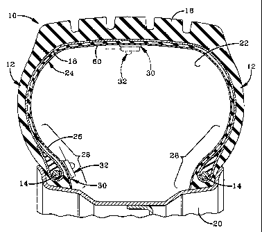
Fig. 1 is a sectional view of a pneumatic tire with a monitoring device
attached to the innerliner of the pneumatic tire by the method of the present
invention;
Fig. 2 is a perspective view of a monitoring device attached to the
innerliner of the pneumatic tire by the method of the present invention;
Fig. 3 is a perspective view of the monitoring device lifted away from the
innerliner to show the treatment of the innerliner and the monitoring device
according to the concepts of the present invention;
Fig. 4 is a plan view of an unencapsulated monitoring device; and
6
CA 02291498 1999-12-03
EXPRESS MAIL NO. EL045970098US
Fig. 5 is an enlarged sectional view similar to Fig. 1 showing an
encapsulated monitoring device attached to the innerliner of a pneumatic tire.
Similar numbers refer to similar elements throughout the specification.
DESCRIPTION OF THE PREFERRED EMBODIMENT
A pneumatic article in the nature of a vehicle tire is depicted in the
drawings and is indicated generally by the numeral 10. Tire 10 is of known
construction and includes a pair of sidewalls 12 which extend outwardly from a
pair of bead rings 14. A tread package 16 is located at the outer ends of
sidewalls 12. Tire 10 further includes a plurality of cords or belts 18 that
provide
structural strength to tire 10. Tire 10 is supported on a rim 20 in a,manner
that
provides an inner chamber 22 between tire 10 and rim 20. Inner chamber 22 is
filled with pressurized air when tire 10 is in use to allow tire 10 to support
the
weight of the vehicle on which tire 10 is used. The pressurized air in chamber
22 is maintained in tire 10 by an innerliner 24 that is substantially
impervious to
air. Innerliner 24 is of known construction and includes not only butyl rubber
but
also chloro-butyl rubber, bromo-butyl rubber, and combinations thereof with up
to less than 50% natural rubber. It is known in the tire building art that it
is
difficult to bond to innerliner 24.
The body of tire 10 is formed from a flexible and somewhat compliant
rubber that flexes and stretches when tire 10 is in use. The movement of tire
10
is also transferred to innerliner 24 complicating the problem of bonding an
article
7
__ ;
CA 02291498 2007-03-15
to the inner surface 26 of innerliner 24. The structure of tire 10 results in
areas of
tire 10 that flex more than other areas of tire 10. The areas that flex the
least are
the areas closest to rim 20. These areas are the low flex areas 28 that extend
approximately 25% up sidewalls 12 and in some tire 10 configurations extends
up
to 50% of the height of sidewall 12. In most tire 10 configurations, low flex
area
28 is 25% of the height of sidewalls 12.
It is also known in the art that innerliner 24 is formed in different
thicknesses for different tires 10. The thickest innerliners 24 are used on
off-the-
road tires that are used with large vehicles. The thickness of off-the-road
innerliners 24 are typically greater than at least 0.06 inch and are
frequently
greater than 1/4 of an inch. Many truck and bus radial tires have innerliners
greater than at least 0.06 inch whereas most passenger tires have an
innerliner
24 that is less than 0.06 inch thick.
An objective of the present invention is to provide an attachment 30 that
may be used to connect a monitoring device 32 to innerliner 24 of tire 10 in a
manner that securely holds monitoring device 32 in position when tire 10 is
used
throughout the life of tire 10. Monitoring device 32 may be any of a variety
of
monitoring devices known in the art. In the embodiment of the invention
depicted
in the drawings, monitoring device 32 is an active electronic monitoring
device
that includes a microprocessor 34, a pressure sensor 36, and a battery 38 such
as shown and described in U.S. Patent Nos. 5,562,787, 5,573,611, 5,500,065,
and 5,573,610.
Each of these elements may be supported on a board or substrate 40 and
connected to an antenna 42. It is desired in the art to encapsulate monitoring
device 32 in a structurally stable housing 44 that may be a substantially
rigid
epoxy. Monitoring device 32 includes a bottom surface 46 that is used to bond
monitoring device 32 to inner surface 26 of innerliner 24.
In accordance with another objective of the present invention, the method
of attaching monitoring device 32 to innerliner 24 includes the following
steps. A
8
CA 02291498 2007-03-15
location on innerliner 24 in low flex area 28 is first selected to connect
monitoring
device 32. The selected location is first roughened to provide a roughened
surface 50 that will accept the adhesive used in the present invention. This
roughening may be performed by a buffing tool such as a tungsten carbide tool,
sand blasting or by a variety of other known tools. Inner surface 26 of
innerliner
24 is roughened by removing about 1 mil of material but preferably about 2
mils
to remove the cure skin of innerliner 24 that is formed when tire 10 is cured.
Roughened area 50 is then cleaned with an innerliner cleaner or a rubber
cleaner
such as cleaner fluid order no. 16-480 supplied by Patch Rubber Company a
division of Myers Industries, Akron, Ohio. The cleaner may also be any
degreasing solvent such as a 1, 1,2-trichloroethylene or heptane.
Roughened area 50 is then primed with a positive chlorine compound such
as any chlorinated primer. A 3% trichlorotriazinetrione solution in butyl
acetate is
preferred.
9
CA 02291498 1999-12-03
EXPRESS MAIL NO. EL045970098US
Generally, any conventional rubber primer known to the art and to the
literature can be utilized. Heretofore, typically chlorine or chlorine-
containing
compounds have been utilized to prime rubber. That is, a halogen or preferably
a chlorine donor compound is utilized. A preferred rubber primer of the
present
invention is trichlorotriazinetrione which can be applied to the rubber as by
brushing, spraying, etc., desirably in a multiplicity of-coats. For example, a
3
percent trichlorotriazinetione solution in butyl acetate can be applied in a
plurality
of coatings such as three, allowing several minutes, e.g., 5 minutes drying
time
between coatings. Immediately after application of the last coating, its
surface
can be wiped off with RYMPLECLOTH to remove by-products such as oils
which migrate to the surface. The rubber surface can then be allowed to dry at
ambient temperature for about 10 to 15 minutes.
Other rubber primers include the various N-halohydantoins, the various
= N-haloamides, the various N-haloimides, and combinations thereof. Examples
of various desirable N-halohydantoins include 1,3-dichloro-5, 5-dimethyl
hydantoin; 1,3-dibromo-5,5-dimethyl hydantoin;l,3-dichloro-5-methyl-5-isobutyl
hydantoin; and 1,3-dichloro-5-methyl-5-hexyl hydantoin. Examples of N-
haloamides include N-bromoacetamide and tetrachloroglycoluril. Examples of
N-haloimides include N-bromosuccinimide and the various chloro substituted s-
triazinetriones, commonly known as mono-, di-, and trichloroisocyanuric acid.
The various mono-, di-, or tri-chloroisocyanuric acids, or combinations
thereof
are a preferred rubber primer with trichloroisocyanuric acid being especially
CA 02291498 1999-12-03
EXPRESS MAIL NO. EL045970098US
preferred. A#hree percent by weight trichloroisocyanuric acid solution in
butyl
acetate is available from Lord Corporation as Chemlok 7707.
The various N-halohydantoins, N-haloamides, and N-haloimide rubber
primers usually exist in solid form. They are readily soluble in polar solvent
such
as acetone and can be applied in liquid form. Application of these rubber
primers generally occur at ambient temperatures. Application can be in any
conventional manner as through brushing, spraying, and the like. A typical
amount of the N-halohydantoins, N-haloamides, and N-haloimide primer in the
solvent, for example, ethyl acetate or acetone, is generally from about 0.1 to
about 10 percent by weight based upon the total weight of said rubber primer
and solvent, and preferably is from about 0.5 percent to about 5 percent. Of
course, higher or lower concentrations can be utilized. This solvent system
has
been found to dry within a matter of minutes so that the adhesive can be
applied
shortly thereafter. It is thought that the rubber primer adds halogen groups,
for
is example, chlorine to the cured rubber bead which activates the surface
thereof,
allowing the adhesive to adhere strongly to the cured rubber surface. Still
additional rubber primers include various acetamides such as chloroacetamide,
bromoacetamide, iodoacetamide, and the like. The thickness of the rubber
primer layer can vary greatly and often is thin since it reacts with the
rubber.
The primer 48 is allowed to dry thoroughly on area 50 before monitoring
device 32 is bonded to innerliner 24. Bottom surface 46 of monitoring device
32
is then degreased using acetone on a purified cheesecloth such as
11
-_ ~
CA 02291498 1999-12-03
EXPRESS MAIL NO. EL045970098US
RYMPLECLOTH brand, sold by American Fiber and Finishing, Inc. of
Westford, MA, and may also be textured to increase its surface area and
ability
to bond.
Monitoring device 32 is then bonded to area 50 using a suitable adhesive
52. A preferred adhesive 52 is an epoxy adhesive such as the FUSOR
310B/320 adhesive that is available from Lord Corporation of Cary, NC.
Adhesive 52 is generally characterized as having a high viscosity at room
temperature and capable of curing at temperatures of 100 C or lower. Adhesive
52 generally consists of essentially epoxy and amine having a ratio of 2.5
parts
epoxy to one part amine curative. Adhesive 52 may be spread on bottom
surface 46 and area 50.. Monitoring device 32 is then placed on area 50 with
sufficient pressure to squeeze excess adhesive 52 out from under monitoring
device 32. The excess adhesive 52 is removed and monitoring device is held
in place by a suitable device such as a clamp or a piece of tape (not shown).
Monitoring device 32 is held in place and adhesive 52 is allowed to cure for
16
to 24 hours. When a faster cure is desired, heat can be applied to decrease
the
cure period. Adhesive 52 is substantially rigid when it cures.
Rigid cured adhesives are not generally compatible with areas of tire 10
that move and flex when tire 10 is used. The above adhesive attachment
system functions best when innerliner 24 is thick enough to allow inner
surface
26 thereof to form a rigid bond with adhesive 52. Innerliners 24 on off-the-
road
tires 10 and on many truck and bus tires are typically thick enough to allow
12
CA 02291498 1999-12-03
EXPRESS MAIL NO. EL045970098US
attachment 30 to properly function. The rigid bond is not disturbed or broken
when tire 10 and innerlinef 24 flex as a result of forces on tire 10 because
of the
thickness of innerliner 24. As can be perhaps best seen in Fig. 5, a
significant
portion 54 of innerliner 24 remains intact between roughened portion 50 and
the
body of tired 10. Innerliner portion 54 flexes with tire 10 and functions as a
buffer that accommodates the flexing and movement of tire 10 without breaking
the bond between adhesive 52 and innerliner 24. This accommodation is
possible because innerliner 24 is thick in off-the-road and on certain truck
and
bus tires 10. When the thickness of portion 54 of innerliner 24 is decreased,
the
flex and movement of the body of tire 10 have a better chance of breaking the
rigid adhesive 52 that connects monitoring device 32 to innerliner 24. When
attachment 30 of the present invention is used on innerliner 24 of an off-the-
road
or truck and bus tires, innerliner portion 54 flexes enough throughout the
life of
tire 10 to prevent the bond between adhesive 52 and innerliner 24 from
breaking
throughout the life of tire 10.
Attachment 30 may also be used to connect monitoring device 32 to a
different location on tire 10 such as the top surface 60 of tire 10 as
depicted in
the dashed lines shown in Fig. 1. A monitoring device 32 may be attached to
top surface 60 when the configuration of tire 10 results in top portion 60
having
low flex properties.
Attachment 30 thus achieves the objectives of the present invention by
providing a lightweight attachment that securely attaches monitoring device 32
13
CA 02291498 1999-12-03
EXPRESS MAIL NO. EL045970098US
to innerliner 24 throughout the life of tire 10. Tire 10 thus does not have to
be
excessively counterbalanced because attachment 30 is lightweight. Attachment
30 may also be easily created by automated equipment on an existing
automated tire manufacturing line because attachment 30 does not require
additional structural elements to be added to tire 10 or monitoring device 32
such as the flaps of the prior art that cover monitoring device 32 to hold
monitoring device 32 in a pocket. Likewise, attachment 30 further does not
require monitoring device 32 to be embedded within the body of tire 10.
Accordingly, the improved attachment for connecting a monitoring device
32 to innerliner 24 of tire 10 is simplified, provides an effective, safe,
inexpensive, and efficient device which achieves all the enumerated
objectives,
provides for eliminating difficulties encountered with prior devices, and
solves
problems and obtains new results in the art.
In the foregoing description, certain terms have been used for brevity,
cleamess, and understanding; but no unnecessary limitations are to be implied
therefrom beyond the requirement of the prior art, because such terms are used
for descriptive purposes and are intended to be broadly construed.
Moreover, the description and illustration of the invention is by way of
example, and the scope of the invention is not limited to the exact details
shown
or described.
Having now described the features, discoveries, and principles of the
invention, the manner in which the attachment of the present invention is
14
CA 02291498 1999-12-03
EXPRESS MAIL NO. EL045970098US
constructed and used, the characteristics of the construction, and the
- advantageous new and useful results obtained; the new and useful structures,
devices, elements, arrangements, parts, and combinations are set forth in the
appended claims.