Language selection

Search

Patent 2291525 Summary

Third-party information liability

Some of the information on this Web page has been provided by external sources. The Government of Canada is not responsible for the accuracy, reliability or currency of the information supplied by external sources. Users wishing to rely upon this information should consult directly with the source of the information. Content provided by external sources is not subject to official languages, privacy and accessibility requirements.

Claims and Abstract availability

Any discrepancies in the text and image of the Claims and Abstract are due to differing posting times. Text of the Claims and Abstract are posted:

  • At the time the application is open to public inspection;
  • At the time of issue of the patent (grant).
(12) Patent: (11) CA 2291525
(54) English Title: OZONE GENERATOR
(54) French Title: OZONEUR
Status: Expired and beyond the Period of Reversal
Bibliographic Data
(51) International Patent Classification (IPC):
  • C01B 13/11 (2006.01)
  • C02F 1/78 (2006.01)
(72) Inventors :
  • COOPER, DONALD M. (Canada)
  • GRINGUAZ, VITALI (Canada)
(73) Owners :
  • A. H. SIMPSON INDUSTRIES LIMITED
(71) Applicants :
  • A. H. SIMPSON INDUSTRIES LIMITED (Canada)
(74) Agent: DENNISON ASSOCIATES
(74) Associate agent:
(45) Issued: 2009-02-17
(22) Filed Date: 1999-12-03
(41) Open to Public Inspection: 2001-06-03
Examination requested: 2004-12-01
Availability of licence: N/A
Dedicated to the Public: N/A
(25) Language of filing: English

Patent Cooperation Treaty (PCT): No

(30) Application Priority Data: None

Abstracts

English Abstract

An ozone generator comprises an electrode located within a dielectric tube with a ground electrode formed on the outer surface of the tube. The tube and ground electrode are surrounded by a coding jacket to allow the coolant to come into contact with the ground electrode and provide efficient cooling.


French Abstract

Un ozoneur comprend une électrode située à l'intérieur d'un tube diélectrique avec une électrode de masse formée sur la surface extérieure du tube. Le tube et l'électrode de masse sont entourés par une enveloppe de codage pour permettre au réfrigérant de venir en contact avec l'électrode de masse et fournir un refroidissement efficace.

Claims

Note: Claims are shown in the official language in which they were submitted.

CLAIMS
1. An ozone generator comprising an active electrode to be connected to a
power
supply, a housing encompassing said electrode to define an enclosed chamber
through which gas can flow and having a wall formed from a dielectric
material, a
ground electrode disposed on the opposite side of said wall to said electrode
and a
coolant contacting said ground electrode to remove heat therefrom.
2. An ozone generator according to Claim 1 wherein said electrode is located
on a
dielectric support.
3. An ozone generator according to claim 2 wherein said electrode extends
about
said support.
4. An ozone generator according to claim 1 wherein said coolant is contained
within
a jacket extending over and spaced from said electrode.
5. An ozone generator according to claim 4 wherein said housing is tubular.
6. An ozone generator according to claim 5 wherein said active electrode is
tubular
and is supported on a cylindrical rod within said housing.
4

Description

Note: Descriptions are shown in the official language in which they were submitted.


CA 02291525 1999-12-03
OZONE GENERATOR
The present invention relates to an ozone generator.
Ozone is a gas that has an aggressive oxidizing action and is used among other
things to sterilize water. In this application the gas is bubbled through the
water and
contaminants are oxidized and may be removed during the subsequent processing.
Ozone may be generated by subjecting an oxygen bearing gas, typically air, to
a
high intensity electric field. The electric field is applied by imposing a
high frequency
voltage between a pair of electrodes as air passes between the electrodes.
The application of the high voltage at high frequency generates significant
heat
which must be removed by cooling. In typical installation the voltage is
applied to an
active electrode and the electric field established between the active
electrode and a
ground electrode. The electrodes face each other and the gas is passed between
them to
generate the ozone. The ground electrode is supported on an insulating
structure which
in turn is encompassed by a cooling jacket.
The application of high frequency current to the electrode produces
significant
heat which in turn must be removed efficiently by the cooling jacket. The
efficiency of
the ozone generation is in part a function of the temperature of the gas and
accordingly
efficient heat removal is a prime consideration. However the support of the
electrode
within an insulating structure inhibits heat transfer from the ozone-producing
region and
thereby limits the efficiencies that may be attained in conventional
apparatus.
It is therefore an object of the present invention to provide an ozone
generator in
which the above disadvantages are obviated or mitigated.
In general terms the present invention provides an ozone generator comprising
an
active electrode to be connected to a power supply, a housing encompassing
said
electrode to define an enclosed chamber through which gas can flow and having
a wall
formed from a dielectric material, a ground electrode disposed on the opposite
side of
said wall to said electrode and a coolant contacting said ground electrode to
remove heat
therefrom.
An embodiment of the invention will now be described by way of example only
with reference to the accompanying drawings in which
1

CA 02291525 1999-12-03
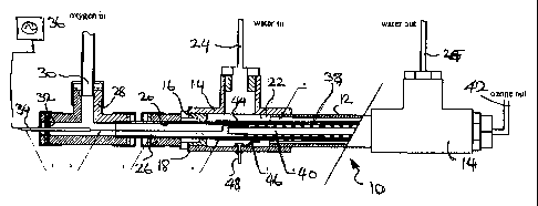
Figure 1 is a side view, partly in section of an ozone generator.
Figure 2 is an enlarged view of a portion of the generator shown in Figure 1.
Figure 3 is a section on the line 3-3 of Figure 2.
Referring therefore to Figure 1, an ozone generator generally indicated 10
includes an outer tubular body 12 extending between a pair of T fittings 14.
Each of the
T fittings 14 has an end cap 16 with a through bore 18 to receive a support
tube 20. The
support tube 20 is formed by a wall of a dielectric material, typically
ceramics and
extends through the body 12 to project beyond each of the end caps 16. The
tube 20 and
the body 12 in conjunction with the end caps 16 define a cooling chamber 22
through
which water can circulate from an inlet port 24 in one branch of one of the
fittings 14 to a
corresponding outlet port 25 on the other fitting. The tube 20 extends through
a
protective boss 26 to a second T fitting 28. The fitting 28 has a gas inlet
port 30 that
receives a supply of oxygen gas and a sealing plate 32 in the branch aligned
with the tube
20. The sealing plate 32 supports an electrical conductor 34 that is connected
to a high
voltage oscillating power source 36. The power source 36 is a power unit
available from
Plasma Technics Inc. of Rancine, Wisconsin and provides a 6-kilovolt supply at
20
kilohertz.
The conductor 34 passes through the interior of the tube 20 and is connected
to an
electrode 38. The electrode 38 comprises a stainless steel wire mesh that is
supported on
a cylindrical dielectric rod 40 within the tube 20. The mesh 38 is wrapped
about the rod
40 and provides a sliding fit within the interior of the tube 20. The
interweaving of the
mesh 38 provides voids through which the gas may pass from the inlet 30 along
the
interior of the tube to an outlet 42 in the opposite end fitting 14.
A ground electrode 44 is formed on the outer surface of the tube 20 from a
conductive epoxy coating. Typically the electrode 44 is a silver filled epoxy
such as that
available from Chomerics Div. of Parker Hannifin Corp. of Wolbum, Maine.
The ground electrode 44 is connected through cable 46 to a ground termina148
provided in the fitting 14.
In operation, oxygen bearing gas typically air or air enriched with oxygen is
fed
through the inlet 30 and along the interior of the tube 20 to the outlet 42.
Power is
supplied from the power supply 36 to the electrode 38 to generate an
alternating electric
2

CA 02291525 1999-12-03
field between the electrodes 38, 44. As the gas passes the electrode a portion
of the
oxygen in the gas is converted to ozone and passing through the outlet 42.
The heat generated is removed by water flowing through the inlet 24 and
through
the chamber 22 to the outlet 25. The water is in intimate contact with the
ground
electrode 44 and thus provides an efficient heat removal.
During operation, the close fit of the grid between the rod 40 and the tube 20
promotes turbulence in the gas flow to facilitate the conversion process. In
preliminary
tests, ozone generation in the order of 10 grams per hour has been achieved
using a 6-
kilovolt 20 hertz supply. In this arrangement, the radial spacing between the
support 40
and tube 20 is in the order of 1.5 millimeters with a diameter of the rod 40
is
approximately 6 millimeters. The efficiency of the cooling provided by the
chamber 22
is such that the body 12 and fittings 14 may be made from PVC and the fittings
in contact
with the ozone are made from kynar. However it should be noted that as the
cooling and
ozone generation functions are separated by the tube 20 the fittings on the
cooling jacket
may be conventional PVC fittings.
The dielectric tube 20 and rod 40 are preferably an alumina ceramic AD 998
available from Coors Ceramics Company, Golden, Colorado or an equivalent
material.
Enhanced performance from the generator may be obtained by utilizing oxygen
rather than air as a feed or enriching an air stream with oxygen. An improved
performance may also be attained by chilling the coolant flow to maintain the
ambient
temperature of the air at a minimum.
The generators 10 may be arranged in an array with similar units, either in
series
flow or parallel flow, to provide the requisite mass flow.
Alternative coolants may be used to water including air if sufficient heat
transfer can be attained.
3

Representative Drawing
A single figure which represents the drawing illustrating the invention.
Administrative Status

2024-08-01:As part of the Next Generation Patents (NGP) transition, the Canadian Patents Database (CPD) now contains a more detailed Event History, which replicates the Event Log of our new back-office solution.

Please note that "Inactive:" events refers to events no longer in use in our new back-office solution.

For a clearer understanding of the status of the application/patent presented on this page, the site Disclaimer , as well as the definitions for Patent , Event History , Maintenance Fee  and Payment History  should be consulted.

Event History

Description Date
Time Limit for Reversal Expired 2017-12-04
Letter Sent 2016-12-05
Grant by Issuance 2009-02-17
Inactive: Cover page published 2009-02-16
Inactive: Final fee received 2008-12-10
Pre-grant 2008-12-10
Notice of Allowance is Issued 2008-07-10
Letter Sent 2008-07-10
Notice of Allowance is Issued 2008-07-10
Inactive: IPC assigned 2008-07-07
Inactive: Approved for allowance (AFA) 2008-06-27
Amendment Received - Voluntary Amendment 2008-03-31
Small Entity Declaration Request Received 2007-11-30
Small Entity Declaration Determined Compliant 2007-11-30
Inactive: S.30(2) Rules - Examiner requisition 2007-10-04
Revocation of Agent Requirements Determined Compliant 2006-10-17
Inactive: Office letter 2006-10-17
Appointment of Agent Requirements Determined Compliant 2006-10-17
Appointment of Agent Request 2006-09-26
Revocation of Agent Request 2006-09-26
Inactive: Office letter 2005-12-20
Appointment of Agent Requirements Determined Compliant 2005-12-20
Revocation of Agent Requirements Determined Compliant 2005-12-20
Letter Sent 2005-12-20
Inactive: Office letter 2005-12-20
Appointment of Agent Request 2005-11-29
Reinstatement Requirements Deemed Compliant for All Abandonment Reasons 2005-11-29
Revocation of Agent Request 2005-11-29
Letter Sent 2005-11-29
Inactive: Office letter 2005-10-04
Letter Sent 2005-10-03
Deemed Abandoned - Failure to Respond to Maintenance Fee Notice 2004-12-03
Request for Examination Received 2004-12-01
Request for Examination Requirements Determined Compliant 2004-12-01
All Requirements for Examination Determined Compliant 2004-12-01
Inactive: Agents merged 2003-02-05
Inactive: Cover page published 2001-06-03
Application Published (Open to Public Inspection) 2001-06-03
Letter Sent 2001-03-19
Inactive: Single transfer 2001-03-05
Inactive: First IPC assigned 2000-01-21
Inactive: Courtesy letter - Evidence 2000-01-11
Inactive: Filing certificate - No RFE (English) 2000-01-07
Filing Requirements Determined Compliant 2000-01-07
Application Received - Regular National 2000-01-06

Abandonment History

Abandonment Date Reason Reinstatement Date
2004-12-03

Maintenance Fee

The last payment was received on 2008-10-29

Note : If the full payment has not been received on or before the date indicated, a further fee may be required which may be one of the following

  • the reinstatement fee;
  • the late payment fee; or
  • additional fee to reverse deemed expiry.

Please refer to the CIPO Patent Fees web page to see all current fee amounts.

Fee History

Fee Type Anniversary Year Due Date Paid Date
Application fee - small 1999-12-03
Registration of a document 1999-12-03
MF (application, 2nd anniv.) - small 02 2001-12-03 2001-11-29
MF (application, 3rd anniv.) - small 03 2002-12-03 2002-12-02
MF (application, 4th anniv.) - small 04 2003-12-03 2003-11-25
Request for examination - small 2004-12-01
2004-12-01
MF (application, 6th anniv.) - small 06 2005-12-05 2005-11-29
Reinstatement 2005-11-29
MF (application, 5th anniv.) - small 05 2004-12-03 2005-11-29
MF (application, 7th anniv.) - small 07 2006-12-04 2006-12-04
MF (application, 8th anniv.) - small 08 2007-12-03 2007-11-30
MF (application, 9th anniv.) - small 09 2008-12-03 2008-10-29
Final fee - small 2008-12-10
MF (patent, 10th anniv.) - small 2009-12-03 2009-11-05
MF (patent, 11th anniv.) - small 2010-12-03 2010-12-02
MF (patent, 12th anniv.) - small 2011-12-05 2011-10-06
MF (patent, 13th anniv.) - small 2012-12-03 2012-11-26
MF (patent, 14th anniv.) - small 2013-12-03 2013-12-02
MF (patent, 15th anniv.) - small 2014-12-03 2014-12-01
MF (patent, 16th anniv.) - small 2015-12-03 2015-12-03
Owners on Record

Note: Records showing the ownership history in alphabetical order.

Current Owners on Record
A. H. SIMPSON INDUSTRIES LIMITED
Past Owners on Record
DONALD M. COOPER
VITALI GRINGUAZ
Past Owners that do not appear in the "Owners on Record" listing will appear in other documentation within the application.
Documents

To view selected files, please enter reCAPTCHA code :


To view images, click a link in the Document Description column. To download the documents, select one or more checkboxes in the first column and then click the "Download Selected in PDF format (Zip Archive)" or the "Download Selected as Single PDF" button.

List of published and non-published patent-specific documents on the CPD .

If you have any difficulty accessing content, you can call the Client Service Centre at 1-866-997-1936 or send them an e-mail at CIPO Client Service Centre.


Document
Description 
Date
(yyyy-mm-dd) 
Number of pages   Size of Image (KB) 
Representative drawing 2001-06-01 1 11
Claims 1999-12-03 1 24
Drawings 1999-12-03 3 61
Abstract 1999-12-03 1 10
Description 1999-12-03 3 156
Cover Page 2001-06-01 1 28
Drawings 2008-03-31 3 61
Representative drawing 2009-01-27 1 12
Cover Page 2009-01-27 1 35
Filing Certificate (English) 2000-01-07 1 164
Request for evidence or missing transfer 2000-12-05 1 109
Courtesy - Certificate of registration (related document(s)) 2001-03-19 1 113
Reminder of maintenance fee due 2001-08-06 1 112
Reminder - Request for Examination 2004-08-04 1 117
Courtesy - Abandonment Letter (Maintenance Fee) 2005-01-31 1 175
Acknowledgement of Request for Examination 2005-10-03 1 177
Notice of Reinstatement 2005-12-20 1 165
Commissioner's Notice - Application Found Allowable 2008-07-10 1 164
Maintenance Fee Notice 2017-01-16 1 178
Maintenance Fee Notice 2017-01-16 1 179
Correspondence 2000-01-07 1 15
Fees 2002-12-02 1 29
Fees 2003-11-25 1 27
Fees 2004-12-01 1 35
Correspondence 2005-10-03 1 17
Correspondence 2005-11-29 1 21
Correspondence 2005-11-29 3 127
Fees 2005-11-29 2 85
Correspondence 2005-12-20 1 13
Correspondence 2005-12-20 1 16
Correspondence 2006-09-26 2 60
Correspondence 2006-10-17 1 15
Correspondence 2006-10-17 1 17
Correspondence 2007-11-30 1 15
Correspondence 2008-12-10 1 37