Language selection

Search

Patent 2291978 Summary

Third-party information liability

Some of the information on this Web page has been provided by external sources. The Government of Canada is not responsible for the accuracy, reliability or currency of the information supplied by external sources. Users wishing to rely upon this information should consult directly with the source of the information. Content provided by external sources is not subject to official languages, privacy and accessibility requirements.

Claims and Abstract availability

Any discrepancies in the text and image of the Claims and Abstract are due to differing posting times. Text of the Claims and Abstract are posted:

  • At the time the application is open to public inspection;
  • At the time of issue of the patent (grant).
(12) Patent Application: (11) CA 2291978
(54) English Title: BEARING ASSEMBLY
(54) French Title: ROULEMENT
Status: Deemed Abandoned and Beyond the Period of Reinstatement - Pending Response to Notice of Disregarded Communication
Bibliographic Data
(51) International Patent Classification (IPC):
  • F16C 19/04 (2006.01)
  • F16C 19/54 (2006.01)
  • F16C 33/60 (2006.01)
  • F16C 35/06 (2006.01)
  • F16C 35/077 (2006.01)
(72) Inventors :
  • CHUANG, WILLIAM (Taiwan, Province of China)
(73) Owners :
  • WILLIAM CHUANG
(71) Applicants :
  • WILLIAM CHUANG (Taiwan, Province of China)
(74) Agent: SMART & BIGGAR LP
(74) Associate agent:
(45) Issued:
(22) Filed Date: 1999-12-10
(41) Open to Public Inspection: 2001-06-10
Examination requested: 2001-01-12
Availability of licence: N/A
Dedicated to the Public: N/A
(25) Language of filing: English

Patent Cooperation Treaty (PCT): No

(30) Application Priority Data: None

Abstracts

English Abstract


A bearing assembly with at least one row of balls is disclosed. The bearing
assembly has a
shaft tube, at least one pair of bearing covers pressed onto the shaft tube, a
concave surface
formed in facing sides of each of the bearing covers, a row of balls received
in the
corresponding concave surfaces of the pair of bearing covers and a race
arranged on the outer
periphery of the row of balls to receive them. The bearing assembly can be
arranged with
multiple rows of balls to improve the ability to bear a large load between the
rotating and
stationary members.


Claims

Note: Claims are shown in the official language in which they were submitted.

6
The embodiment of the invention in which an exclusive property or privilege is
claimed are
defined as follows:
1. A bearing assembly comprising:
a shaft tube;
at least one pair of bearing covers pressed onto said shaft tube, a concave
surface formed
on a face of each of the bearing covers, and a row of balls received in said
concave surfaces of
said pair of bearing covers; and
a race formed to enclose said row of balls therein;
wherein said concave surfaces of each of the bearing covers corresponds to
each other.
2. The bearing assembly as claimed in claim 1, wherein an enlarged end with a
diameter
larger than that of said shaft tube is formed on one end of said shaft tube,
and a securing collar
is pressed onto the other end of said shaft tube.
3. A bearing assembly comprising:
a shaft tube;
at least two pairs of bearing covers pressed onto said shaft tube, a concave
surface
formed on a face of each of the bearing covers, a row of balls received
between the pairs of
bearing covers and a race arranged around each row of balls between each said
pair of bearing
covers,
wherein said concave surface of each pair of bearing covers corresponds to
each other.
4. The bearing assembly as claimed in claim 3, wherein a spacer collar mounted
on said
shaft tube is located between adjacent pairs of bearing covers.
5. The bearing assembly as claimed in claim 3 further comprising a sleeve
securely
mounted on the outer periphery of all of said races.
6. The bearing assembly as claimed in claim 5, wherein multiple recesses are
defined on
the outer periphery of said sleeve.

Description

Note: Descriptions are shown in the official language in which they were submitted.


CA 02291978 1999-12-10
, 2
1 BEARING ASSEMBLY
2 BACKC~ROL1ND OF THE INVENTION
3 1. Field of the Invention
4 The present invention relates to a bearing assembly, and more particularly
to a bearing
assembly with multiple rows of balls mounted therein to bear a heavier load.
6 BRT_EF DESCRIPTION OF THF DR_A_WT_NC~S
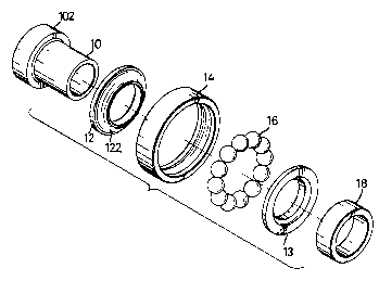
7 Fig. 1 is a perspective view of a bearing assembly with one row of balls in
accordance
8 with the present invention;
9 Fig. 2 is an exploded perspective view of the bearing assembly in Fig. 1;
Fig. 3 is a cross sectional plan view of the bearing assembly in Fig. l;
11 Fig. 4 is an exploded perspective view of a bearing assembly with two rows
of balls in
12 accordance with the present invention;
13 Fig. S is a cross sectional plan view of the bearing assembly in Fig. 4;
14 Fig. 6 is a cross sectional plan view of an embodiment of a bearing with
multiple rows of
bails in accordance with the present invention;
16 Fig. 7 is a cross sectional plan view of another embodiment of a bearing
with multiple
17 rows of balls in accordance with the present invention;
18 Fig. 8 is a cross sectional plan view of a bearing with one row of balls in
accordance with
19 the prior art; and
Fig. 9 is a cross sectional plan view of a bearing with two rows of balls in
accordance
21 with the prior art.
22 2. Description of Related Art
23 Referring to Fig. 8, a ball bearing in accordance with the prior art
comprises a bearing
24 cover (40), a positioning collar (44), multiple balls (46) and a bearing
race (42). The
positioning collar (44) is co-axially mounted on the bearing cover (40). A row
of balls (46) is

CA 02291978 1999-12-10
1 located between the bearing cover (40) and the positioning collar (44) in a
bearing race (42),
2 such that the race (46) can rotate relative to the bearing cover (40) and
the positioning collar
3 (44) with very little friction. However, because the ability to bear a load
depends on the
4 number of rows of balls (46), the conventional bearing with a single row of
balls (46) is not
able to bear a large load between the rotating and stationary members. In
addition, the
6 conventional bearing is difficult to manufacture and assemble because the
structure of the
7 bearing cover (40) is complex.
8 Referring to Fig. 9, a bearing with two rows of balls (54) in accordance
with the prior art
9 comprises a tubular member (50) and a sleeve (52) mounted on the outer
periphery of the
tubular member (50). A row of balls (54) is received between the tubular
member (50) and
11 the sleeve (52) on each end of the sleeve (52), and a holder (56) is
mounted to abut each row
12 of balls (54) to maintain their position. The sleeve (52) can rotate
relative to the tubular
13 member (50) with little friction, and a bearing with two rows of balls (54)
is achieved.
14 However, although the conventional bearing with two rows of balls (54) can
bear a
heavier load better than that of the conventional bearing with a single row of
balls, the
16 conventional bearing with two rows of balls (54) still lacks the ability to
bear a very large
17 load. In addition, there is no supporting effect between the rows of balls
(54) when they are a
18 long distance apart.
19 To overcome the shortcomings, the present invention tends to provide an
improved
bearing assembly to mitigate or obviate the aforementioned problems.
21 SI1MMARY OF THE INVENTION
22 The main objective of the invention is to provide a bearing assembly with a
shaft tube, at
23 least one pair of bearing covers with a row of balls between the covers and
a race so that the
24 bearing assembly can be arranged with multiple rows of balls to improve the
ability to bear a
large load.

CA 02291978 1999-12-10
4
1 Other objects, advantages and novel features of the invention will become
more apparent
2 from the following detailed description when taken in conjunction with the
accompanying
3 drawings.
4 DFTA1_LED DESG IPTION OF P RF . RFD .MBODI .NT
Referring to Figs. 1-3, the bearing assembly in accordance with the present
invention
6 comprises a shaft tube ( 10), a bearing housing, bearing balls ( 16) and a
securing collar ( 18). A
7 pair of annular bearing covers ( 12, 13) for each row of bearing balls ( 16)
is press fit on the
8 outer periphery of the shaft tube ( 10). A concave surface ( 122, 132) is
defined in the facing
9 side of each of the bearing covers (12, 13). A row of balls (16) is received
between the
concave surfaces ( 122, 132) of the pair of bearing covers ( 12,13 ). A race (
14) with a concave
11 inner surface corresponding to the curvature of the bearing balls ( 16) is
arranged around the
12 row of balls ( 16), such that the race ( 14) can rotate relative to the
shaft tube ( 10) and the pair
13 of bearing covers (12, 13) and decrease the friction between the rotating
and stationary
14 members.
In addition, an enlarged positioning end ( 102) with a diameter larger than
that of the
16 shaft tube ( 10) is formed on one end of the shaft to abut one of the
bearing covers ( 12), and a
17 securing collar ( 18) is pressed onto the other end of the shaft tube ( 10)
to abut the other
18 bearing cover (13). The bearing covers (12, 13) are more securely mounted
on the shaft tube
19 ( 10) and rotate together.
Referring to Figs. 4 and 5, two pairs of bearing covers ( 12, 13 ) are mounted
on the shaft
21 tube ( 10), and each pair of bearing covers ( 12, 13) has one row of balls
( 16) held between the
22 pair of covers (12, 13). A spacer collar (20) is mounted on the shaft tube
(10) between the two
23 pairs of collars (12, 13) to maintain their separation from each other.
With such an
24 arrangement, the bearing assembly can bear a load better than that of the
conventional
bearing (shown in Fig. 8) with a single row of balls. In addition, because the
shaft tube ( 10),

CA 02291978 1999-12-10
1 the bearing covers ( 12, 13), the race ( 14), the securing collar ( 18) and
the spacer collar (20)
2 are tubular or annular members with a simple shape, the efficiency of
manufacturing and
3 assembling the bearing assembly is improved.
4 With reference to Fig. 6, another embodiment of a bearing assembly in
accordance with
5 the present invention has multiple pairs of bearing covers (12, 13) and a
row of bearing balls
6 (14) between each pair of covers (12, 13). A spacer collar (20) is arranged
between adjacent
7 pairs of bearing covers (12, 13). With reference to Fig. 7, another
embodiment has the
8 adjacent pairs of bearing covers (12, 13) abutting each other. Consequently,
the bearing
9 assembly can be arranged with multiple rows of balls ( 16) so as to improve
the ability to bear
a huge load.
11 In addition, a sleeve (22) is mounted on the outer periphery of all of the
races ( 14), such
12 that all of the races ( 14) can rotate relative to the shaft tube ( 10)
simultaneously. Furthermore,
13 multiple recesses (222) are defined in the outer periphery of the sleeve
(22) to improve the
14 bond between the sleeve (22) and the member to which the sleeve (22) is
mounted.
Even though numerous characteristics and advantages of the present invention
have been
16 set forth in the foregoing description, together with details of the
structure and function of the
17 invention, the disclosure is illustrative only, and changes may be made in
detail, especially in
18 matters of shape, size, and arrangement of parts within the principles of
the invention to the
19 full extent indicated by the broad general meaning of the terms in which
the appended claims
are expressed.

Representative Drawing
A single figure which represents the drawing illustrating the invention.
Administrative Status

2024-08-01:As part of the Next Generation Patents (NGP) transition, the Canadian Patents Database (CPD) now contains a more detailed Event History, which replicates the Event Log of our new back-office solution.

Please note that "Inactive:" events refers to events no longer in use in our new back-office solution.

For a clearer understanding of the status of the application/patent presented on this page, the site Disclaimer , as well as the definitions for Patent , Event History , Maintenance Fee  and Payment History  should be consulted.

Event History

Description Date
Inactive: IPC from MCD 2006-03-12
Application Not Reinstated by Deadline 2004-12-10
Time Limit for Reversal Expired 2004-12-10
Deemed Abandoned - Failure to Respond to Maintenance Fee Notice 2003-12-10
Inactive: Cover page published 2001-06-10
Application Published (Open to Public Inspection) 2001-06-10
Letter Sent 2001-01-31
Request for Examination Requirements Determined Compliant 2001-01-12
All Requirements for Examination Determined Compliant 2001-01-12
Request for Examination Received 2001-01-12
Inactive: First IPC assigned 2000-01-26
Inactive: IPC assigned 2000-01-26
Inactive: Filing certificate - No RFE (English) 2000-01-14
Filing Requirements Determined Compliant 2000-01-14
Application Received - Regular National 2000-01-11

Abandonment History

Abandonment Date Reason Reinstatement Date
2003-12-10

Maintenance Fee

The last payment was received on 2002-11-26

Note : If the full payment has not been received on or before the date indicated, a further fee may be required which may be one of the following

  • the reinstatement fee;
  • the late payment fee; or
  • additional fee to reverse deemed expiry.

Please refer to the CIPO Patent Fees web page to see all current fee amounts.

Fee History

Fee Type Anniversary Year Due Date Paid Date
Application fee - small 1999-12-10
Request for examination - small 2001-01-12
MF (application, 2nd anniv.) - small 02 2001-12-10 2001-11-26
MF (application, 3rd anniv.) - small 03 2002-12-10 2002-11-26
Owners on Record

Note: Records showing the ownership history in alphabetical order.

Current Owners on Record
WILLIAM CHUANG
Past Owners on Record
None
Past Owners that do not appear in the "Owners on Record" listing will appear in other documentation within the application.
Documents

To view selected files, please enter reCAPTCHA code :


To view images, click a link in the Document Description column. To download the documents, select one or more checkboxes in the first column and then click the "Download Selected in PDF format (Zip Archive)" or the "Download Selected as Single PDF" button.

List of published and non-published patent-specific documents on the CPD .

If you have any difficulty accessing content, you can call the Client Service Centre at 1-866-997-1936 or send them an e-mail at CIPO Client Service Centre.


Document
Description 
Date
(yyyy-mm-dd) 
Number of pages   Size of Image (KB) 
Representative drawing 2001-06-04 1 10
Abstract 1999-12-10 1 17
Description 1999-12-10 4 186
Drawings 1999-12-10 6 107
Claims 1999-12-10 1 44
Cover Page 2001-06-04 1 31
Filing Certificate (English) 2000-01-14 1 164
Acknowledgement of Request for Examination 2001-01-31 1 179
Reminder of maintenance fee due 2001-08-13 1 116
Courtesy - Abandonment Letter (Maintenance Fee) 2004-02-04 1 176
Fees 2002-11-26 1 32
Fees 2001-11-26 1 31