Note: Descriptions are shown in the official language in which they were submitted.
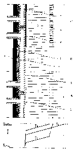
CA 02292529 1999-12-03
WO 98!54367 PCT/EP98/03194
REFRACTORY WALL STRUCTURE
The invention relates to a refractory wall structure
for a furnace, in particular for a metallurgical furnace,
such as for example a blast furnace with a high process
temperature during operation, which wall structure is
subjected to a high thermal loading, comprising
- a steel outer wall,
- a refractory lining consisting of one or more layers
of a well heat-conducting material on the inside of
the outer wall, and
- means for cooling the refractory wail structure.
With the wall structure of this type, the refractory
lining is exposed to a high temperature. As a consequence
of this, considerable wear of the refractory lining occurs
and its service life is reduced. At the state of the art
the reference temperature is kept low by cooling and
attempts are made to keep the interior temperature low by
using refractory materials with a high heat conductivity,
such as graphite, semi-graphite or other refractory
materials containing graphite. The means for cooling the
refractory wall structure can consist of means on the
outside of the steel wall, such as for example spray-
cooling, air-cooling or cooling ducts for fluid coolants,
or of other means on the inside of the steel wall such as
for example water-cooled cooling elements such as stave
coolers or cooling plates which are generally made from
copper.
SUBSTITUTE SHEET (RULE 26)
CA 02292529 1999-12-03
o r..- . ec
:9 , ~ r.
~ r
n r r
n . . r r r . .
n
r r
-2-
The object of the invention is to reduce the wear of
this wall structure and to improve the service life.
The object of the invention is also to create a repair
process for the refractory wall structure of a Furnace
which prolongs the service life.
With the invention this is achieved because the wall
structure also comprises a permanent, well heat-conducting
metallic filling in a gap in the refractory wall
structure, which filling has been molten inside the gap
and then after solidifying forms a low heat resistance
across the gap.
The invention relies on the notion that the gaps which
inevitably occur or form in the refractory wall structure
which is always of a composite nature, form considerable
heat resistances for the flow of dissipating heat passing
through, so that the interior temperature of the
refractory lining remains high. The filling, which in
molten state has a close thermal contact with the gap
walls, which contact remains unchanged following
solidification, and the good heat conductivity of the
material of the filling, together provide a low heat
resistance across the gap, so that the interior
temperature of the refractory lining falls. In certain
cases, a layer such as slag can even solidify onto and
build up on the inside. This results in a permanent, wear-
resistant layer.
In W095/22732 a construction of a wall lining for a
furnace is described in which high thermal conductivity
AMEND 'p SHEET ,
CA 02292529 1999-12-03
t i O r =. ~ r
1. q ' .
P ! , 1 ! l-' ,~ ( ~
( ( ~ c a
( f ! ! . (
1 . l ~ ' ! i f ~ ( .
f t t f
-2a-
elements extend from a cooled metal outer shell into a
refractory lining. These elements may themselves consist
of a refractory material of which the pores have been
impregnated with a metal. This patent application does not
deal with the reduction of heat barriers which arP,",rfo.rmed
by gaps between refractory bricks or between elements and
refractory bricks.
Preferably the gap with a good heat conducting
metallic filling is a gap in the refractory lining, or a
LNG ~ SH~~ v
P~~
CA 02292529 1999-12-03
WO 98/54367 PCT/EP98I03194
-3-
gap between the steel outer wall and the refractory
lining, or, if the means for cooling the refractory wall
structure are water-cooled copper cooling elements, a gap
between the refractory lining and a cooling element. A gap
in the refractory lining can be a gap between two layers
of the refractory lining, or a gap between two elements
such as blocks or bricks of the refractory lining, or a
gap such as a heat crack in the material of the refractory
lining. The most effective are fillings in gaps which lie
at right-angles to the flow of heat, so that the heat
resistance for the heat dissipation is reduced.
The melting temperature of the metallic filling is
preferably lower than the process temperature, higher than
200 °C and lower than 1,100 °C and the filling has a
coefficient of heat conductivity of over 15 W/m °C.
The filling is preferably selected from the group
consisting of tin, lead, zinc, aluminium, silver, copper
and alloys of these and combinations of these.
Preferably the filling is obtained during operation by
melting of foil which is applied in the gap during
assembly of the refractory wall structure, the filling is
cast into the gap in molten state during assembly or the
filling is obtained during operation by melting a metal
which is applied in the gap in the form of a mass
containing metal particles during assembly of the
refractory wall structure. These embodiments of the
invention are all very effective.
SU8ST1TUTE SHEET (RULE 26)
ICA 02292529 1999-12-03
WO 98/54367 PCT/EP98/03194
-4-
The embodiment with a mass containing metal particles
is also suitable for wider gaps such as joints which are
normally filled up with mortar, concrete, ramming mass,
cement or other binding agents such as for example the
joint between jacket (1) and graphite layer (3') in Fig.
2. Metal particles in the form of powder, grains,
granulated material, chips, needles, small wires or
similar are added to this mass. This metal-laden mass is
applied in a joint during assembly of the refractory wall
structure. In this state the metal particles are evenly
divided present in the relevant joint, but still do not
form a heat bridge over the joint. Following melting and
solidification again of the metal, however, the joint is
not homogeneously filled with metal but at sufficient
loading of the mass with metal particles of for example
10-40 ovol a continuous metal lattice with a spongy or
biscuit-like structure forms throughout the joint with a
low heat resistance owing to the good heat conductivity of
the metal and thus forms a heat bridge.
Also preferably the filling is obtained during
operation by melting metal in the form of one or more
pellets which are placed into one or more cavities in the
refractory wall structure before or after the start of the
operation of the furnace. In some cases in an alternative
embodiment pellets can also be applied during operation.
In this context pellets are taken to be a form of the
filling which can be applied into the cavity singly or in
multiples, such as tablets of round, oval or cylindrical
SUBSTITUTE SHEET (RULE 2fi)
CA 02292529 1999-12-03
WO 98/54367
_5_
PCT/EP98/03194
shape, but also shaped parts which f it into the cavity, or
for example in rod-shaped pieces in the case where they
are applied subsequently during operation. Capsules with a
dosing opening are also possible so that the filling is
discharged over a longer period of time or several times,
for example where the refractory wall structure breathes
in the event of temperature fluctuations.
Preferably the filling is obtained during operation by
melting metal which is introduced in the form of a
pumpable mass containing the metal into the refractory
wall structure through a duct. The pumpable mass can for
example be a slurry or a suspension, which is laden with
the metal in finely divided state such as powder or grains
to such an extent, for example 10 to 60 °swt, that it does
not sag. Preferably the pumpable mass also contains an oil
product such as tar or pitch or a thermosetting resin as a
carrier and the pumpable mass also contains graphite for
example in the form of powder. Mortar and cement can also
be added. After the pumpable mass has been introduced into
the gap by pumps the metal melts and forms a heat bridge
over the gap. Following coking the tar or the pitch forms
a skeleton which for example effects a certain aas
tightness of the gap. The same effect can be obtained by
the resin following setting, while the graphite can yield
extra wear resistance and/or heat conduction of the
refractory wall structure. The embodiments of the
invention with pellets and with a pumpable mass are
SUBSTITUTE SHEET (RULE 26)
ICA 02292529 1999-12-03
WO 98/54367 PCT/EP98/03194
_g_
particularly suited to be applied after starting the
operation of the furnace.
Preferably during assembly of the refractory wall
structure cooling elements are used which, at least
partly, have been provided with a coating with the
substance of the metallic filling. By a coating here is
understood a layer which during its application has
obtained a good heat-transfer contact with the cooling
element.
For instance the coating can have been applied by
melting a layer of the substance upon the cooling element,
by immersing the cooling element in a melt of that
substance, by electrodeposition or by spraying.
The aforementioned embodiments of the invention can be
combined with each other. Thus, the embodiment for example
whereby a mass containing metal particles is applied in a
gap during assembly, can ideally be combined with
application of a pumpable mass in that gap after starting
the operation.
In another aspect the invention is embodied in a
method for repairing a blast furnace during operation with
a refractory wall structure in accordance with Claim 1,
comprising a steel outer wall (jacket), a refractory
lining (brickwork) and means for cooling the refractory
wall structure comprising the stages
- during operation drilling a duct through the steel
outer wail and into the refractory lining extending
into or past a gap in the refractory wall structure
SUBSTITUTE SHEET (RULE 26)
CA 02292529 1999-12-03
WO 98/54367
PCTIEP98I03194
during operation introducing into the duct a metal
with a melting point in the vicinity of the
instantaneous temperature at the gap.
Preferably the metal is introduced in the form of one
or more pellets or in the form of a pumpable mass
containing the metal, by pumps.
In a preferred embodiment, whereby the means for
cooling the refractory wall structure comprise stave
coolers, recesses are left in the stave coolers through
which during operation a duct may be drilled.
The invention will now be illustrated by reference to
the drawing.
Fig. 1 shows a refractory wall structure in accordance
with the invention in a general embodiment in different
stages of wear together with the associated temperature
curve.
Fig. 2 shows as example of the invention a refractory
wall structure for a hearth of a blast furnace.
Fig. 3 shows as example of the invention a refractory
wall structure for a final reduction vessel of a smelting
reduction process.
The refractory wall structure of Fig. 1 comprises a
steel outer wall (1), means of cooling in the form of
water-cooled, copper stave coolers (2} and a well heat-
conducting refractory lining (3), for example of graphite.
The space between the steel outer wall and the stave
coolers (2) is filled up with for example mortar (4).
SUBSTITUTE SHEET (RULE 2B)
ICA 02292529 1999-12-03
WO 98/54367 PCTIEP98/03194
_g_
The situation directly following starting the
operation of the furnace is indicated by A, whereby no
wear has yet occurred and the refractory lining ( 3 ) still
has its original thickness. The associated temperature
curve is indicated by TA in the bottom part of Fig. 1.
Tprocess indicates the process temperature and Tcao1
indicates the reference temperature of the cooling. The
figure shows that a considerable fall in temperature
occurs across the gap (5) between stave coolers (2) and
refractory lining (3) as a result of the high heat
resistance of gap (5).
The situation after the furnace has been in operation
for some time is indicated by B. The refractory lining (3)
is partly worn away as a result of the high temperature
and the corrosive conditions. In particular slag
containing Fe0 is especially corrosive. TB indicates the
temperature curve. As a result of the reduced thickness of
refractory lining (3), the total heat transmission
resistance of the wall structure has reduced, and the heat
flow density has increased through the wall structure.
This results in a steeper temperature curve across the
residual thickness of refractory lining (3) and a greater
temperature drop across gap (5). If the process of wear is
allowed to continue then refractory lining (3) becomes
further consumed and the risk of breakthrough increases.
C indicates the situation with a metallic filling (6)
in gap (5) which filling has been molten and therefrom
continues to maintain a good thermal contact with the gap
SUBSTITUTE SHEET (RULE 26)
CA 02292529 1999-12-03
WO 98/54367 PCT/EP98/03194
_g_
walls. In this case the filling is a low melting point
metal such as for example a tin alloy. Tc shows that, as a
result of the low heat resistance of the filling, the
temperature drop across gap (5) is much less. The
temperature of refractory lining (3) falls so that a slag
layer (7) can solidify, which of itself does not conduct
heat well, so that a big temperature drop occurs across
it, but which protects the residual thickness of
refractory lining (3) from further wear. Filling (6) can
be cast into gap (5) during assembly of the refractory
wall structure or be applied there as a film which in
situation B will melt.
Fig. 2 shows the invention applied to the hearth of a
blast furnace. Jacket (1) is cooled on the outside by
means of spray-cooling (2). In the case shown here,
refractory lining (3) consists of two layers, namely layer
(3') of graphite and a layer (3 ") of semi-graphite. A
ramming compound of graphite is applied in gap (5) between
layers ( 3' ) and ( 3 " } . Situations A and B are analogous to
that of Fig. 1. In situation B a considerable part of
inner coating layer (3 ") has worn away and a considerable
temperature drop is occurring across gap (5).
The figure shows how in situation B the wall structure
is repaired after the start of the operation and during
operation. To this end ducts (8) are drilled through
jacket (1}, mortar layer (4) and refractory lining layer
( 3 ' ) , which ducts ( 8 ) extend into or past gap ( 5 ) between
lining layers (3') and (3 "). In general drilling cannot
SUBSTITUTE SHEET (RULE 26)
_._~. _ ,~._ . _. ___'
ICA 02292529 1999-12-03
WO 98/54367 PCT/EP98103194
- 10-
take place during the production of pig iron because the
furnace is under pressure. Therefore the holes are drilled
during operation but during a so-called standstill or
maintenance stop whereby the production of pig iron is
interrupted and whereby the hot blast is switched off and
the pressure falls out. At a new furnace, however, the
ducts can already be made wholly or partly during assembly
of the refractory wall structure. Following drilling one
or more pellets (9) of a metal with a melting point in the
vicinity of the instantaneous temperature at the gap are
introduced into the holes. once the ducts have been
drilled this temperature may be measured and the metal
selected accordingly. In this case the metal can be an
alloy of aluminium or copper. When pellets (9) melt the
metal runs into gap (5). The reduced heat resistance of
gap (5) makes the temperature drop fall across gap (5),
and the temperature of the outer lining layer (3 ") falls.
Filling (6) solidifies and slag layer (7) can solidify and
build up. Of course pellets (9) can also be placed in
suitable places in the refractory wall structure prior to
the operation of the blast furnace. If pellets are placed
through such ducts as (8) or similar then these ducts may
of course be filled in and sealed (possibly temporarily)
after the pellets have been placed.
In another embodiment the ducts (8) can be provided
with nipples (not shown) on the outside of the jacket (1)
to which a pressure pipe is connected, through which a
pumpable mass containing the metal can be pressed into the
SUBSTITUTE SHEET (RULE 26)
CA 02292529 1999-12-03
WO 98/54367 PCTIEP98/03194
-11-
ducts (8). The mass then spreads over the gaps in the
refractory wall structure and following melting etc. forms
heat bridges over the gaps. Contrary to drilling pumping
can take place at a furnace under pressure.
Fig. 3 shows an invention applied to a final reduction
vessel for a smelting reduction process, for example of
the deep slag type such as for example the Cyclone
Converter Furnace (CCF) process. The thermal loading here
is especially high. Consequently in Fig. 3 not only are
stave coolers (2) used, but also water-cooled copper sills
(10) which extend into the refractory lining and which
serve to improve the heat contact between the refractory
lining and the means of cooling (2), (10). Refractory
lining (3) consists of at least a layer (3') of graphite.
The means of cooling {2), (10) limit the possibilities of
applying pellets afterwards, that is to say during
operation. Consequently in this case it was decided to
apply pellets (9) during the assembly of the refractory
wall structure into suitable cavities (11) in the
refractory wall structure, which pellets f ill gap (5) as
they melt on commissioning, or once refractory lining (3)
has partly worn away. The cavities may also be made for
example directly above sills (l0). There is also the
possibility to let recesses into the stave coolers through
which a duct can be drilled during operation.
Finally there is the possibility to use, during the
assembly, cooling elements which on the side directed to
gap (5) have been coated. The low heat-resistance across
SUBSTITUTE SHEET (RULE 26)
CA 02292529 1999-12-03
WO 98/54367
-'i2-
PCT/EP98/03194
the gap (5) can be achieved already during the assembly,
by assembling the refractory lining (3) while, at least at
the side facing the gap, being heated such that the
filling melts.
A low heat resistance can, however, also be obtained
later during the operation.
SUBSTITUTE SHEET (RULE 26)