Note: Descriptions are shown in the official language in which they were submitted.
CA 02292590 1999-12-O1
WO 98157112 PCT/US98/07023
Air Preheater Heat Transfer Elements
and Method of Manufacture
Background of the Invention
The present invention relates to rotary regenerative air preheaters
for the transfer of heat from a flue gas stream to an incoming
combustion air stream and particularly to the configuration of the heat
transfer elements for the air preheater and the method of manufacturing
those elements.
A rotary regenerative heat exchanger is employed to transfer heat
from one hot gas stream, such as a hot flue gas stream, to another cold
gas stream, such as combustion air. The rotor contains a mass of heat
absorbent material which first rotates through a passageway for the hot
gas stream where heat is absorbed by the heat absorbent material. As
the rotor continues to turn, the heated absorbent material enters the
passageway for the cold gas stream where the heat is transferred from
the absorbent material to the cold gas stream.
In a typical rotary heat exchanger, such as a rotary regenerative
air preheater, the cylindrical rotor is disposed on a horizontal or vertical
central rotor post and divided into a plurality of sector-shaped
compartments by a plurality of radial partitions, referred to as
diaphragms, extending from the rotor post to the outer peripheral shell
of the rotor. These sector-shaped compartments are loaded with
modular heat exchange baskets which contain the mass of heat
absorbent material commonly formed of stacked plate-like heat transfer
elements.
Conventional heat transfer elements for regenerative air
preheaters are form-pressed or roll-pressed steel sheets or plates which
are then stacked to form the mass of heat transfer material. One typical
arrangement is for the plates to be formed with spaced apart ridges,
usually double ridges projecting from opposite sides of the plate, which
CA 02292590 1999-12-O1
WO 98/57112 PCT/US98/07023
2
extend along the plate either in the direction of flow or obliquely thereto
and which serve to space the plates from each other. The spacing
forms the flow channels between the plates for the flow of flue gas and
air. For examples of such heat transfer elements, reference is made to
U.S. Patents 4,744,410 and 4,553,458.
One of the effects of using these ridges to provide the spacing of
the heat transfer elements is that they form flow paths through the
bundle of heat transfer elements which are larger in cross-sectional area
per surface area of exposed plate surface than the cross-sectional area
per surface area of the other portions of the plate. This results in lower
flow resistance, less turbulence and mixing, greater mass flow of gas
and air and lower heat transfer as compared to the remainder of the
plates. Therefore, although the ridges do provide structural integrity and
accurate spacings, they have their negative effect on heat transfer.
Summary of the invention
The present invention relates to the method of forming heat
transfer elements and to the heat transfer elements formed by the
method whereby the heat transfer performance of the heat transfer
elements is improved. Specifically, the invention relates to heat transfer
elements which have spacing ridges or notches formed across the plates
wherein flow-disrupting indentations are formed at selected intervals in
the peaks of the notches which project into the portions of the flow
channels formed by the notches. The flow-disrupting projections
change the size of the flow channel (height, width, and /or cross
sectional area), interrupt the boundary layer, cause turbulence and
mixing and result in enhanced heat transfer.
CA 02292590 1999-12-O1
WO 98/57112 PCT/US98/07023
3
Brief Description of the Drawings
Figure 1 is a general perspective view of a conventional rotary
regenerative air preheater.
Figure 2 is a perspective view of a portion of a heat transfer
element assembly incorporating the present invention.
Figure 3 is a side view of a portion of a heat transfer element
assembly illustrating the flow channels.
Figure 4 is an enlarged perspective view of a portion of one heat
transfer plate illustrating the present invention.
Figure 5 is a section view of a portion of a plate forming method
illustrating the formation of plates with the notches.
Figure 6 is a view of another section of the rolls of Figure 5
showing the means for forming the flow disrupting indentations.
Figure 7 is a perspective view of a portion of one of the rolls of
Figures 5 and 6.
Figure 8 is a section view of a portion of an alternate plate
forming method of the present invention.
Figure 9 is a front view of the indentation forming rollers of Figure
8.
Figure 10 is a perspective view of a portion of a heat transfer
element assembly of the present invention applied to undulating plates.
Description of the Preferred Embodiment
Figure 1 of the drawings is a partially cut-away perspective view
of a typical air heater showing a housing 12 in which the rotor 14 is
mounted on drive shaft or post 16 for rotation as indicated by the arrow
18. The rotor is composed of a plurality of sectors 20 with each sector
containing a number of basket modules 22 and with each sector being
defined by the diaphragms 34. The basket modules contain the heat
exchange surface. The housing is divided by means of the flow
CA 02292590 1999-12-O1
WO 98/57112 PCTIUS98/07023
4
impervious sector plate 24 into a flue gas side and an air side. A
corresponding sector plate is also located on the bottom of the unit.
The hot flue gases enter the air heater through the gas inlet duct 26,
flow through the rotor where heat is transferred to the rotor and then
exit through gas outlet duct 28. The countercurrent flowing air enters
through air inlet duct 30, flows through the rotor where it picks up heat
and then exits through air outlet duct 32.
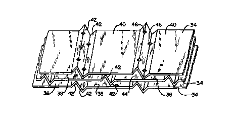
Figure 2 depicts portions of three of the stacked heat exchange
plates 34 which are contained in the basket modules 22 and which are
formed in accordance with the present invention. Of course, there
would be a large number of such plates 34 in each module. The plates
34 are stacked in spaced relationship thereby providing passageways 36
and 38 therebetween for the flow of flue gas and air.
The plates 34 are usually formed of thin sheet metal and are
capable of being rolled or stamped to the desired configuration. The
plates are formed with flat sections 40 and opposed notches 42 which
provide the means for spacing the adjacent plates a predetermined
distance apart to form the previously mentioned flow channels or
passageways 36 and 38. As can be seen more clearly in Figure 3 which
shows a side view of a portion of three stacked plates, the available
area 44 for the flow of fluid between the notches 42 and the adjacent
plate which is shown as being cross-hatched is significantly greater per
surface area of exposed heat transfer surface than the remaining
/uncross-hatched? area for the flow of fluid between the flat sections 40
of adjacent plates. This flow path 44 has lower flow resistance and less
turbulence and mixing. A greater percentage of the flow per heat
transfer surface area of exposed element passes through these channels
44 than through the remainder of the flow passageways 38 and also
through the flow passages 36. All of these factors result in a lower
heat transfer in this area 44.
CA 02292590 1999-12-O1
WO 98/57112 PCT/US98/07023
The present invention provides means in the flow channels 44 to
disrupt the flow thereby minimally increasing flow resistance, creating
. turbulence and mixing and disrupting the boundary layer. The flow
disrupting means thereby improves the specific heat transfer
5 performance in the channels 44 and the overall heat transfer
performance of the stacked plates. It also serves to push some of the
flow out of the notch channel and intermixes it with the flow in the
other areas, for example, flow passages 36 and 38 in Figures 2 and 3.
This intermixing reduces temperature differences between the fluid in
passage 44 and passages 36 and 38, which would otherwise exist.
Figure 2 shows the flow disrupting means which comprise
deformations or indentations 46 which are formed into the peaks of the
notches 42 to extend into the channels 44 at spaced intervals. These
indentations are also shown in Figure 4 which is an enlarged view of a
portion of one plate 34 showing these indentations more clearly. As
can be seen most clearly in Figure 4, the dent 46 in the upwardly
extending, left hand notch 42 comprises a small depression in the peak
of the notch such that the underside of the indentation 46 extends
down into flow area 44 under the plate. Likewise, the downwaraly
extending, right hand notch 42 has an indentation 46 which is similarly
formed and which extends up into the right hand flow area 44 on top
of the plate.
These flow disrupting means or indentations 46, because they
. extend into the fluid flow path through the channels 44 disrupt the
boundary layer and create turbulence and mixing thereby improving the
heat transfer. in fact, the improvement in heat transfer can be
significant even when the dents 46 are quite small and without the need
to have them closely spaced. For example with a notch height of 0.38
inches (the distance from the top of one notch extending from one side
of the plate to the top of the paired notch extending from the other side
CA 02292590 1999-12-O1
WO 98157112 PCT/US98/07023
6
of the plate), indentations spaced at 2.5 inch intervals with an average
depth of only 0.100 inches show an increase of 9.5 % in heat transfer
for an equal volume or quantity of heat transfer plates. Or, because the
plates can now be spaced further apart due to the increased heat
transfer, a comparable heat transfer can be obtained with 8% less plate
material in the modules than for plates without the present invention.
Figures 5, 6 and 7 illustrate the equipment used in one method of
forming the heat transfer plates of the present invention. In this
method, the opposed forming rolls 48 and 50 which are used to form
the notches 42 in the plate 34 are modified to form the indentations 46.
Figure 5 is a cross section through the rolls and through the plate at a
location where there are no indentations. The projections 52 on the
forming roils cooperate with the depressions 54 to form the notches 42.
Figure 6, which is a figure similar to Figure 5, is a cross-section
through the rolls and through the plate at a location where the means
for forming the indentation are located. Figure 7 is a perspective view
of a portion of one roll which also illustrates these indentation forming
means. As shown, the projections 52 on the forming rolls are cut away
at 56 in the shape and to the extent required to form the indentations
46. The depressions 54 are fitted with denting pins 58 which project
upwardly from the bottom of the depressions 54 and which cooperate
with the mating cut away portions 56 on the matching roll to form the
indentations.
Figures 8 and 9 illustrate another method of forming the
indentations 46 in the heat transfer plates of the present invention. In
Figure 8, the forming rolls 60 and 62 are similar to the forming rolls 48
and 50~ of Figure 5 but they are only for the purpose of forming the
notches 42. They are not modified to form the indentations 46. In the
Figure 8 and 9 method, the plate 34 with the formed notches 42 is
passed through the indentation forming rollers 64 and 66. The roller 64
CA 02292590 1999-12-O1
WO 98/57112 PCT/US98/07023
7
comprises a series of disks 68 which are spaced apart a distance equal
to the desired spacing between indentations as shown in Figure 9. The
roller 64 preferably has spacers 72 between the disks 68 such that the
spacers 72 of varying widths can be used to vary the distance between
dents. The circumferential edges of the disks 68 are shaped and aligned
such that they will engage the notches 42 and form indentations of the
desired shape and depth.
The roller 66 is for the purpose of supporting the notches on the
sides of the indentations as they are being formed. This provides
control of the depth of the indentations and prevents unwanted
deformation of the sheet except in the specific area of the indentations.
The roller 66 comprises a series of disks 70 which contain the notch
supports 74. These notch supports are shaped such that they extend
into the notches and conform to the shape of the notches. They are
aligned on the roller 66 so that there is a support disk 70 on each side
of each disk 68 as shown in Figure 9. In Figure 8, the illustrated
support disk 70 is behind the indentation 46 which is being formed. In
this particular method, the indentations are formed only on the notches
on one side of the plate 34 at a time. The plate in Figure 8 would then
progress to the next station where the indentations on the bottom notch
would be formed in the same manner. This embodiment shown in
Figures 8 and 9 is the presently preferred method for forming the
indentations in a step separate from the step of forming the notches.
Another, less preferred method is to replace the roller 66 with a roller
identical to roller 64. The plate then passes between the resulting pair
of rollers 64 which forms reasonable indentations. However, this tends
to reduce the notch height over a larger area rather than just locally.
Although certain heat transfer plate configurations have been
used for illustration, the invention also applies to other configurations of
notched plates. For example, the notches may be oriented parallel to
CA 02292590 1999-12-O1
WO 98/57112 PCT/US98/07023
8
the fluid flow or they may be at an angle up to 45°. The invention also
applies to plates with notches extending out on only one side as
opposed to the illustrated double-sided notch arrangement. Further, the
so-called flat sections of the plates between notches may in fact be an
undulated surface as is common in the art. This embodiment is
illustrated in Figure 10 where the sections 40 between the notches 42
have undulations or corrugations 76 which are relatively shallow
compared to the height of the notches and which are typically inclined
at an acute angle to the direction of the notches and the direction of
fluid flow.
The use of plates having an undulating surface leads to a still
further method of forming the indentations. When the plate to be
notched is already undulated or otherwise contains a significantly
textured surface, the notching rolls can be formed so that they work in
conjunction with the undulations to simultaneously form the notches
and indentations. The notching roll has a discontinuous notch pattern
across the width of the roll. In areas where the notch pattern is
present, the undulation is 'flattened and the notch is roll-formed. Where
there are gaps in the notch pattern on the roll, the existing undulation
shape remains to a significant extent thereby producing the desired
effect of an indentation or bump into the notch channel. This may be
done with the same equipment shown in Figures 5, 6 and 7 but without
the necessity of having the denting pins 58.
Merely by way of example, a plate with a notch height of 0.965
cm (0.380 inches' may have indentations spaced at 6.35 cm (2.5
inches) and to an average depth of 0.254 cm (0.100 inches). The total
width of an indentation may be on the order of 0.635 cm f0.25 inches'.
While specific details of the assembly of heat transfer elements and
several variations of the method of forming the elements have been
CA 02292590 1999-12-O1
WO 98/57112 PCT/US98/07023
9
described, the invention is intended to include equivalents and be limited
only by the claims.