Note: Descriptions are shown in the official language in which they were submitted.
CA 02292737 1999-12-O1
WO 98/58758 PCT/US98/12738
ULTRA-HIGH STRENGTH CRYOGENIC WELDMENTS
This invention relates to methods for producing ultra-high strength weldments
with weld metals having excellent cryogenic temperature fracture toughness.
More
particularly, this invention relates to methods for producing ultra-high
strength
weldments with weld metals having excellent cryogenic temperature fracture
toughness on ultra-high strength, low alloy steels.
BACKGROUND OF THE INVENTION
Various terms are defined in the following specification. For convenience, a
Glossary of terms is provided herein, immediately preceding the claims.
Frequently, there is a need to store and transport pressurized, volatile
fluids at
cryogenic temperatures, i.e., at temperatures lower than about -40°C (-
40°F). For
2 0 example, there is a need for containers for storing and transporting
pressurized
liquefied natural gas (PLNG) at pressures in the broad range of about 1035 kPa
(150
psia) to about 7590 kPa (1100 psia) and at temperatures higher than about -
123°C
(-190°F). There is also a need for containers for safely and
economically storing and
transporting other pressurized fluids, such as methane, ethane, and propane,
at
2 5 cryogenic temperatures. For such containers to be constructed of a welded
steel, the
steel and its weldments (see Glossary) must have adequate strength to
withstand the
fluid pressure and adequate toughness to prevent initiation of a fracture,
i.e., a failure
event, at the operating conditions.
As will be familiar to those skilled in the art, the Charily V-notch (CVN)
test
CA 02292737 1999-12-O1
WO 98/58758 PCT/US98/I2738
2
can be used for the purpose of fracture toughness assessment and fracture
control in
the design of storage containers for transporting pressurized, cryogenic
temperature
fluids, such as PLNG, particularly through use of the ductile-to-brittle
transition
temperature {DBTT). The DBTT delineates two fracture regimes in structural
steels.
At temperatures below the DBTT, failure in the Charily V-notch test tends to
occur by
low energy cleavage (brittle) fracture, while at temperatures above the DBTT,
failure
tends to occur by high energy ductile fracture. Storage and transportation
containers
that are constructed from welded steels for the aforementioned cryogenic
temperature
applications and for other load-bearing, cryogenic temperature service must
have
DBTTs, as determined by the Charily V-notch test, well below the service
temperature
of the structure in order to avoid brittle failure. Depending on the design,
the service
conditions, and/or the requirements of the applicable classification society,
the
required DBTT temperature shift (i.e., how far the DBTT must be below the
intended
service temperature) may be from 5°C to 30°C (9°F to
54°F) below the service
temperature.
Nickel-containing steels conventionally used for cryogenic temperature
structural applications, e.g., steels with nickel contents of greater than
about 3 wt%,
have low DBTTs, but also have relatively low tensile strengths. Typically,
commercially available 3.5 wt% Ni, 5.5 wt% Ni, and 9 wt% Ni steels have DBTTs
of
2 0 about -100°C (-150°F), -155°C (-250°F), and -
175°C (-280°F), respectively, and
tensile strengths of up to about 485 MPa (70 ksi), G20 MPa (90 ksi), and 830
MPa
(120 ksi), respectively. In order to achieve these combinations of strength
and
toughness, these steels generally undergo costly processing, e.g., double
annealing
treatment. In the case of cryogenic temperature applications, industry
currently uses
2 5 these commercial nickel-containing steels because of their good toughness
at low
temperatures, but must design around their relatively low tensile strengths.
The
designs generally require excessive steel thicknesses for load-bearing,
cryogenic
temperature applications. Thus, use of these nickel-containing steels in load-
bearing,
cryogenic temperature applications tends to be expensive due to the high cost
of the
3 0 steel combined with the steel thicknesses required.
CA 02292737 1999-12-O1
WO 98/58758 PCTIUS98/12738
Current commercial storage containers for transportation of liquefied natural
gas at -162°C (-260°F) and atmospheric pressure (LNG) are
typically constructed of the
above-mentioned commercial nickel-containing steels, austenitic stainless
steels, or
aluminum. In LNG applications, the strength and toughness requirements for
such
materials, and for weldments joining such materials, are distinctly different
from those
for the PLNG case. For example, in discussing the welding of 2 '/4 wt% to 9
wt% Ni
steels for cryogenic purposes, G. E. Linnert, in "Welding Metallurgy",
American
Welding Society, 3rd Ed., Vol. 2, 1967, pp. 550-570, lists the Charily V-notch
toughness (see Glossary) requirements for such weldments as ranging from about
20 J
to 61 J as measured at the service temperature. Also, the 1995 publication,
Det
Norske Veritas (DNV) Rules For Classification of Ships, specifies that
materials used
in new-built, liquefied gas carrying ships must meet certain minimum Charily V-
notch
toughness requirements. Specifically, the DNV Rules state that plates and
weldments
used for pressure vessels with design temperatures ranging from -60°C
to -165°C
must meet a minimum Charily toughness of 27 J at test temperatures ranging
from
5°C to 30°C (9°F to 54°F) below the design
temperature. The requirements listed by
Linnert and the DNV Rules cannot be directly applied to the construction of
containers for transportation of PLNG (or other pressurized, cryogenic fluids)
since
the PLNG containment pressure, typically about 2760 kPa (400 psia), is
significantly
2 0 higher than for conventional methods of transporting LNG, which is
generally at or
near atmospheric pressure. For PLNG storage and transportation containers,
there is a
need for more stringent toughness requirements, and therefore, a need for
weldments
with better toughness properties than those now used for constructing LNG
storage
containers.
Base Plate Material
Storage containers for pressurized, cryogenic temperature fluids, such as
PLNG, are preferably constructed from discrete plates of an ultra-high
strength, low
3 0 alloy steel. Three co-pending U.S. provisional patent applications
identify various
CA 02292737 2000-10-27
WO 98/58758 PCT/L1S98/I2738
4
weldable, ultra-high strength, low alloy steels with excellent cryogenic
temperature
toughness for use in constructing storage containers for transporting PLNG and
other
pressurized, cryogenic temperature fluids. The steels are described in a co-
pending
U.S. provisional patent application entitled "ULTRA-HIGH STRENGTH STEELS
WITH EXCELLENT CRYOGENIC TEMPERATURE TOUGHNESS", which has a
priority date of 19 December 1997 and was published as a corresponding
PCT application W099/32672; in a co-pending
U.S. provisional patent application entitled "ULTRA-HIGH STRENGTH AUSAGED
STEELS WITH EXCELLENT CRYOGENIC TEMPERATURE TOUGHNESS",
1 o which has a priority date of 19 December 1997 and was published as a
corresponding
PCT application W099/32670; and in a co-pending U.S. provisional patent
application entitled "ULTRA-HIGH STRENGTH DUAL PHASE STEELS WITH
EXCELLENT CRYOGENIC TEMPERATURE TOUGHNESS", which has a
priority date of 19 December 1997 and was published as a corresponding PCT
application W099/32671. These steels are especially suitable for many
cryogenic
temperature applications, including transportation of PLNG, in that the steels
have the
following characteristics for steel plate thicknesses of preferably about 2.5
cm (1 inch)
and greater: {i) DBTT lower than about -73°C (-100°F),
preferably lower than about
-I07°C (-160°F), in the base steel and in the weld HAZ, (ii)
tensile strength greater
2 0 than 830 MPa {120 ksi) , preferably greater than about 860 MPa (125 ksi),
and more
preferably greater than about 900 MPa (130 ksi), (iii) superior weldability,
(iv)
substantially uniform through-thickness microstructure and properties, and (v)
improved toughness over standard, commercially available, ultra-high strength,
low
alloy steels. The steels described in the above-mentioned co-pending U.S.
provisional
patent applications may have a tensile strength of greater than about 930 MPa
(135
ksi), or greater than about 965 MPa (140 ksi), or greater than about 1000 MPa
(145
ksi). Other suitable steels are described in a European Patent Application
published
February 5, 1997, and having International application number: PCT/JP96/00157,
and International publication number WO 96/23909 (08.08.1996 Gazette 1996/36)
3 0 (such steels preferably having a copper content of 0.1 wt% to 1.2 wt%),
and in a
CA 02292737 2004-05-05
co-pending U.S. provisional patent application entitled "ULTRA-HIGH STRENGTH,
WELDABLE STEELS WITH EXCELLENT ULTRA-LOW TEMPERATURE
TOUGHNESS", which has a priority date of 28 July 1997 and was published
as the corresponding PCT application W099/05335.
S
Welding
Such steels may be joined together to form storage containers for pressurized,
cryogenic temperature fluids, such as PLNG, by a welding method suitable for
producing a weldment that provides adequate strength and fracture toughness
for the
intended application. Such a welding method preferably includes a suitable
welding
process, for example without limitation, gas metal arc welding ("GMAW"),
tungsten
inert gas ("TIG") welding, or submerged arc welding ("SAW"); a suitable
welding
consumable wire; a suitable welding consumable gas (if required); a suitable
welding
flux (if required); and suitable welding procedures, for example without
limitation,
preheat temperatures, and welding heat inputs. A weldment is a welded joint,
including: (i) the weld metal, (ii) the heat-affected zone ("HAZ"), and (iii)
the base
metal in the "near vicinity" of the HAZ. The weld metal is the welding
consumable
wire (and flux, if~used) as deposited and diluted by the portion of the base
metal plate
2 0 that melts during performance of the welding process. The HAZ is the
portion of the
base metal that does not melt during welding, but whose microstructure and
mechanical properties are altered by the heat of the welding process. The
portion of
the base metal that is considered within the "near vicinity" of the HAZ, and
therefore,
a part of the weldment, varies depending on factors known to those skilled in
the art,
2 5 for example without limitation, the width of the weldment, the dimensions
of the base
metal plate that is welded, and the distances between weldments.
Properties of We~dm~nts Desired for~LN~A~,p ~li~ atio,~s
3 0 For the purpose of constructing storage containers for PLNG and other
CA 02292737 1999-12-O1
WO 98158758 PCT/US98112738
6
pressurized, cryogenic temperature fluids, it is desirable to have a welding
method,
including a welding consumable wire, a welding consumable gas, a welding
process,
and welding procedures that will provide weldments with tensile strengths and
fracture
toughnesses suitable for the intended cryogenic application, according to
known
principles of fracture mechanics, as described herein. More particularly, for
constructing storage containers for PLNG, it is desirable to have a welding
method
that will provide weldments with tensile strengths greater than about 900 MPa
(130
ksi} and fracture toughnesses suitable for the PLNG application according to
known
principles of fracture mechanics, as described herein. The tensile strength of
such
weldments is preferably greater than about 930 MPa (135 ksi), more preferably
greater than about 965 MPa (140 ksi), and even more preferably at least about
1000
MPa (145 ksi). Current commercially available welding methods using
commercially
available welding consumable wires are not suitable for welding the
aforementioned
high strength, low alloy steels and providing weldments with the desired
properties
for commercial cryogenic, pressurized applications.
Consequently, the primary objects of the present invention are to improve the
state-of the-art welding technology for applicability to ultra-high strength,
low alloy
steels so as to provide a welding method that will produce weldments that have
tensile
strengths greater than about 900 MPa ( 130 ksi) and fracture toughnesses
suitable for
2 0 the intended cryogenic application according to known principles of
fracture
mechanics, as described herein.
SUMMARY OF THE INVENTION
2 5 A welding method (including a welding consumable wire, a welding process
type, and the selection of certain welding parameters and practices) is
provided that
can be used to join ultra-high strength, low alloy steels with excellent
cryogenic
temperature fracture toughness for cryogenic applications. The welding method
of
this invention is formulated to produce a microstructure yielding a set of
mechanical
3 0 properties suitable for the stringent demands of pressurized, cryogenic
temperature
CA 02292737 2004-12-03
7
fluid applications, such as the PLNG application. The welding method produces
a
weld metal that is dominated by a very fine-grained body centered cubic (BCC)
crystal structure. The welding method also provides a weld metal having a low
impurity content, and thus, a low non-metallic inclusion content and,
additionally,
creates individual inclusions that are small in size. The fundamental effects
of fine
grain size on strength and toughness of structural steels, as well as the
fundamental
effects of low inclusion content on toughness, are well known to those skilled
in the
art. However, techniques for achieving such characteristics in weld metals
suitable
for the PLNG application are not widely known. The weldment resulting from use
of
the welding method of this invention has a tensile strength greater than about
900
MPa (130 ksi) and a toughness adequate for the PLNG application, in accordance
with
known principles of fracture mechanics.
According to an aspect of the present invention, there is provided a method of
welding a base metal to produce a weldment having a tensile strength greater
than
about 900 MPa (130 ksi), said method comprising: (i) welding using a gas
shielded
welding process, an argon-based shielding gas, and a welding consumable wire
that
produces a weld metal that comprises iron and the following alloying elements:
about
0.06 wt % to about 0.10 wt % carbon; about 1.60 wt % to about 2.05 wt
manganese; about 0.20 wt % to about 0.32 wt % silicon; about 1.87 wt % to
about
6.00 wt % nickel; about 0.30 wt % to about 0.87 wt % chromium; and about 0.40
wt
to about 0.56 wt % molybdenum; (ii) controlling heat input during welding to
between 0.3 and 2.5 kJlmm; (iii) using a welding preheat temperature between
room
temperature and about 200°C, the welding preheat temperature being
chosen in
consideration of material weldability and welding heat input; and (iv)
limiting non-
metallic inclusion content and size to less than about 250 inclusions per mm2
of size
larger than about 1000 nm in diameter.
CA 02292737 2004-12-03
7a
According to an aspect of the present invention, there is provided a weldmerxt
having a tensile strength of at least about 900 MPa ( 130 ksi) produced by
welding at
least 2 edges of a base metal using a gas shielded welding process, an argon-
based
shielding gas, and a welding consumable wire, wherein the heat input during
welding
is controlled to between 0.3 and 2.5 kJ/mm, wherein a welding preheat
temperature is
between room temperature and about 200°C, the welding preheat
temperature being
chosen in consideration of material weldability and welding heat input,
wherein non-
metallic inclusion content and size is limited to less than about 250
inclusions per
mmz of size larger than 1000 nm in diameter, and wherein said weldment
comprises
(i) a weld metal that comprises iron and the following alloying elements:
about 0.06
wt % to about 0.10 wt % carbon; about 1.60 wt % to about 2.05 wt % manganese;
about 0.20 wt % to about 0.32 wt % silicon; about 1.87 wt % to about 4.00 wt
nickel; about 0.30 wt % to about 0.87 wt % chromium; and about 0.40 wt % to
about
0.56 wt % molybdenum; (ii) a heat affected zone (HAZ); and (iii) portions of
said
base metal in the near vicinity of the HAZ.
nF~C'I~1PTION OF THE DRAWINGS
The advantages of the present invention will be better understood by referring
to
the following detailed description and the attached drawings in which:
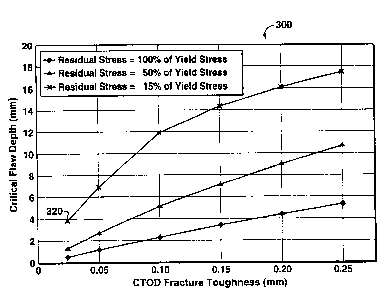
FIG. lA illustrates a plot of critical flaw depth, for a given flaw length, as
a
function of CTOD fracture toughness and of residual stress; and
FIG. 1B illustrates the geometry (length and depth) of a flaw.
While the invention will be described in connection with its preferred
embodiments, it will be understood that the invention is not limited thereto.
On the
contrary, the invention is intended to cover all alternatives, modifications,
and
equivalents which may be included within the spirit and scope of the
invention, as
defined by the appended claims.
CA 02292737 1999-12-O1
WO 98/58758 PCT/US98/12738
8
DETAILED DESCRIPT10N OF THE INVENTION
The present invention relates to a welding method for use in joining ultra-
high
strength, low alloy steels, whereby the resulting weldments have ultra-high
strengths
and excellent cryogenic temperature toughnesses. These desirable properties
are
afforded, primarily, by two micro-engineered aspects of the weld metal. The
first
feature is a very fine-grained body centered cubic (BCC) crystal structure and
the
second feature is a low non-metallic inclusion content wherein the individual
inclusions are small in size. The welding method includes a welding consumable
wire, a welding process type, and the selection of certain welding parameters
and
practices. The preferred welding processes for the welding method of this
invention
are any of the gas shielded processes such as gas metal arc welding (GMAW),
tungsten inert gas welding (TIG), plasma arc welding (PAW), or their
derivatives.
Preferred welding parameters and practices, such as heat input and composition
of
shielding gas, are further described herein.
Chemical Composition of Weld Metals
In one embodiment, a weld metal chemistry according to the present invention
2 0 comprises iron and alloying elements in about the amounts indicated in
Table I and
below.
CA 02292737 1999-12-O1
WO 98/58758 PCTIUS98/12738
9
Table I
Alloying Element Preferred Lower Limit Preferred Upper Limit
_ (wt%) (wt%)
carbon (C) 0.06 0.10
manganese (Mn) 1.60 2.05
silicon {Si) 0.20 0.32
nickel (Ni) 1.87 6.00
chromium (Cr) 0.30 0.87
molybdenum (Mo) 0.40 0.56
copper (Cu) - 0 - 0.30
aluminum (Al) - 0 - 0.020
zirconium (Zr) - 0 - 0.015
titanium (Ti) - 0 - 0.010
More preferably, the upper limit for nickel content is about 4.00 wt%.
The Effect of Fine Grain Size
The fine grain size in the microstructure of a weld metal made according to
this invention increases strength of the weldment through dislocation
blockage. The
fine grain size increases cleavage toughness by shortening the length of
dislocation
pileups which decreases the maximum possible stress intensity at the head of
any
2 5 single pileup. This makes microcrack initiation less probable. The lower
pileup
- intensity also improves ductile fracture toughness by reducing local
microstrains, thus
making microvoid initiation less probable. Additionally, the fine grain size
increases
global toughness by providing many "roadblocks" to crack advance. (See
Glossary
for definitions of dislocation blockage, cleavage toughness, dislocation
pileup,
3 0 microcrack, microstrains, and microvoid.)
CA 02292737 1999-12-O1
WO 98/58758 PCT/US98/12738
Achieving the Microstructure and Grain Size
The fine-grained BCC structure is preferably dominated by auto-tempered lath
5 martensite, i.e., contains at least about 50 volume percent, more preferably
at least
about 70 volume percent, and even more preferably at least about 90 volume
percent,
auto-tempered lath martensite. However, significant amounts of lower bainite
can
also be present, e.g., up to about 49 volume percent. Minor constituents such
as
acicular ferrite, polygonal ferrite, and upper bainite (or other degenerate
forms of
10 bainite} can also be present in small amounts, but preferably do not
constitute the
dominant morphology. The desired martensitic/bainitic microstructure is
achieved by
use of appropriate weld metal chemistry and proper control of the weld metal
cooling
rate. Several examples which discuss chemistries are provided below. Low heat
input welding is used so that the weld metal cools more quickly than it would
with
typically used higher heat inputs. Heat input is defined as the welding
voltage
multiplied by the welding current and divided by the welding travel speed,
i.e., arc
energy. The low heat input welding used in the welding method of this
invention has
arc energies preferably within the range of about 0.3 kJ/mm to about 2.5 kJ/mm
(7.6
kJ/inch to 63.5 kJlinch), but more preferably within the range of about 0.5
kJ/mm to
2 0 about 1.5 kJ/mm (12.7 kJ/inch to 38 kJ/inch). Several different levels of
"grain size"
can be described within the desired microstructure and the low heat input
welding
technique is intended to reduce the size of each unit. A low welding heat
input helps
in the formation of a small columnar grain size, a small prior austenite grain
size, a
small martensite/bainite packet size, and a narrow martensite and/or bainite
lath
2 5 width. As used herein in reference to structure, "fine-grained" means that
the
columnar grain size (width) is preferably less than about 150 microns, and
more
preferably less than about 100 microns; that the prior austenite grain size is
preferably
less than about 50 microns, more preferably less than about 35 microns, and
even
more preferably less than about 20 microns; and that the martensite/bainite
packet size
3 0 is preferably less than about 20 microns, more preferably less than about
15 microns,
CA 02292737 1999-12-O1
WO 98/58758 PCT/US98112738
11
and even more preferably less than about 10 microns. As used herein, "grain
size"
means grain size as determined by the line intercept method, as is familiar to
those
skilled in the art.
The Effect of Low Inclusion Content
The low inclusion content tends to increase cleavage toughness by eliminating
potential cleavage crack initiation sites and/or by reducing the number of
micro-stress
concentration sites. The low inclusion content tends to increase ductile
fracture
1 o toughness by reducing the number of microvoid initiation sites.
Weldments made according to this invention preferably have a low inclusion
content, but are not inclusion-free. Inclusions can contribute significantly
to
achieving optimum weld metal properties. First, they act as deoxidizers in the
molten
weld metal pool. Low oxygen content in the shielding gas is preferred for
making
weldments according to this invention, thus decreasing the need for
deoxidation;
however, some deoxidation potential in the molten weld metal pool is still
preferred.
Second, inclusions can be useful in controlling columnar and prior austenite
grain
growth through grain boundary pinning. Limiting grain growth at elevated
temperatures promotes a small room temperature grain size. However, because
the
2 0 low heat input for making weldments according to this invention helps
limit grain
size, the inclusion content can be reduced to a level that enhances toughness,
but still
provides useful grain boundary pinning effects.
Weldments made according to this invention will achieve high strengths as
previously noted. In the case of lower strength weld metals, it is often a
designed
2 5 feature to created a significant volume fraction of Ti-based inclusions
for the purpose
of nucleating acicular ferrite. For such lower strength weldments, acicular
ferrite is
the preferred microstructure due to its good strength and toughness
properties. For the
current invention, however, where higher strengths are of interest, it is an
intentional
feature to avoid a large volume fraction of inclusions that nucleate acicular
ferrite.
3 0 Rather it is preferred to create a microstructure dominated by lath
martensite.
CA 02292737 1999-12-O1
WO 98/58758 PCT/US98/12738
12
Achieving the Desired Inclusion Size/Content
The preferred low inclusion content in weldments according to the present
invention is afforded by the selection and delivery of an appropriate
shielding gas, by
maintaining good weld cleanliness, and by utilizing a welding consumable wire
with
low amounts of sulfur, phosphorus, oxygen, and silicon. The specific chemistry
of the
welding consumable wire is designed to give the desired weld metal chemistry,
which
in turn is chosen based on the desired mechanical properties. The desired
mechanical
properties depend on the specific container design; and this invention covers
a range
of weld metal chemistries capable of accommodating a range of designs. Using
the
welding method of this invention the bulk weld metal will be minimally diluted
by the
base metal and, therefore, the chemistry of the welding consumable wire will
be
nearly the same as the chemistry of the weld metal as described herein.
According to
the welding technique of this invention, dilution is expected to be less than
about
15%, but often less than about 10%. For areas close to the center of the weld
metal,
dilution is expected to be less than about 5%. Using any well known reverse
dilution
calculation method, one skilled in the art is capable of calculating the
welding
consumable wire chemistry for use in the method of the present invention to
obtain
2 0 the desired weld metal chemistry. The shielding gas is preferably low in
CO, and/or
O, content. Preferably the shielding gas comprises less than about 10 vol%,
more
preferably less than about 5 vol%, and even more preferably less than about 2
vol%,
of CO, and/or OZ. The major component of the shielding gas is preferably
argon; and
the shielding gas preferably comprises about 80 vol% or more argon, and more
2 5 preferably more than about 90 vol%. Helium can be added to the shielding
gas in
amounts up to about 12 vol% to improve arc operating characteristics or weld
bead
penetration and profile. If necessary, for a specific storage container
design,
impurities from the shielding gas that tend to lead to non-metallic inclusion
formation
in the weld metal, as are known to those skilled in the art, can be further
reduced by
3 0 delivering the gas though a nanochem filter, a device known to those
skilled in the art
CA 02292737 1999-12-O1
WO 98158758 PCT/US98/12738
13
of precision TIG welding. To aid the achievement of low weld metal inclusion
content in the weld metal, the welding consumable wire and the base material
are
preferably themselves low in oxygen, sulfur, and phosphorus. The above
features of
the welding method of this invention produce a weld metal that contains
preferably
less than about 150 ppm of P, but more preferably less than about 50 ppm of P,
less
than about 150 ppm of sulfur, but more preferably less than about 30 ppm of
sulfur,
and less than about 300 ppm of oxygen, but more preferably less than about 250
ppm
of oxygen. For certain cryogenic storage container designs, the oxygen content
of the
weld metal is preferably controlled to less than about 200 ppm.
With respect to inclusion size, the low welding heat input that is preferred
for
making weldments according to this invention, is selected to produce limited
superheating and a fast cooling rate, thus limiting the growth time of the
inclusions in
the molten weld metal pool. Additionally, small amounts of Al, Ti, and Zr
{less than
about 0.015 wt. % of each) can be added individually or in combination to form
small
oxides. These elements are selected due to their known high affinity for
oxygen.
With respect to Ti, the amount of this element should be kept low, preferably
less than
about 0.010 wt%, to prevent too much acicular ferrite nucleation. The
inclusions
created by this invention are, on average, less than about 700 nm in diameter,
but
preferably in the range of about 200 nln to about 500 nm in diameter. The
number of
2 0 non-metallic inclusions per unit area, e.g., of the surface of a slice of
the weld metal
created by this invention, that are larger than about 1000 nm in diameter is
preferably
low, i.e., is preferably less than about 250 per mm'.
The Balance Between Preheat and Heat Input
The PLNG application requires a high strength steel which may necessitate
some level of preheat to prevent weld cracking. Preheat can alter the weld
cooling
rate (higher preheat promoting slower cooling) and it is an object of this
invention to
balance preheat and welding heat input so as to (1) preclude weld cracking,
and (2)
3 0 produce a fine-grained microstructure. Preheat is preferably between room
CA 02292737 1999-12-O1
WO 98/58758 PCT/US98/12738
14
temperature and about 200°C (392°F), but as will be familiar to
those skilled in the
art, the specific preheat temperature is preferably chosen in consideration of
material
weldability and welding heat input. Material weldability can be assessed using
any
one of several test methods that are known to those skilled in the art, such
as the
Controlled Thermal Severity Test, the Y-groove test, or the Welding Institute
of
Canada test. "Mock-ups" may also serve this purpose whereby weldments of the
actual base and weld metals are joined using candidate fabrication procedures.
The
mock-ups are preferably of sufficient size to impose the level of restraint
that will
occur in the actual storage container.
Pulsing Po~p~iy
In general, a pulsing power supply can be used with any of the gas shielded
processes that are preferred for use in the welding method of this invention.
Losses in
arc stability or penetration capability due to wire/gas chemistry selections
can, to a
significant degree, be regained using a pulsed power supply. For example, in
the case
that this invention is practiced using low heat input TIG welding and a low
sulfur
consumable wire, weld bead penetration can be enhanced using a pulsing power
supply.
Fracture Control
As will be familiar to those skilled in the art, the operating conditions
taken
into consideration in the design of storage containers constructed from a
welded steel
2 5 for transporting pressurized, cryogenic fluids, include among other
things, the
operating pressure and temperature, as well as additional stresses that are
likely to be
imposed on the steel and the weldments. Standard fracture mechanics
measurements,
such as (i) critical stress intensity factor (K,~), which is a measurement of
plane-strain
fracture toughness, and (ii) crack tip opening displacement {CTOD), which can
be
3 0 used to measure elastic-plastic fracture toughness, both of which are
familiar to those
CA 02292737 1999-12-O1
WO 98158758 PCTIUS98/12738
skilled in the art, may be used to determine the fracture toughness of the
steel and the
weldments. Industry codes generally acceptable for steel structure design, for
example, as presented in the BSI publication "Guidance on methods for
assessing the
- acceptability of flaws in fusion welded structures", often referred to as
"PD 6493:
5 1991 ", may be used to determine the maximum allowable flaw sizes for the
containers
based on the fracture toughness of the steel and weldment (including HAZ) and
the
imposed stresses on the container. A person skilled in the art can develop a
fracture
control program to mitigate fracture initiation through (i) appropriate
container design
to minimize imposed stresses, (ii) appropriate manufacturing quality control
to
10 minimize defects, (iii) appropriate control of life cycle loads and
pressures applied to
the container, and (iv) an appropriate inspection program to reliably detect
flaws and
defects in the container. A preferred design philosophy for storage containers
welded
according to the present invention is "leak before failure", as is familiar to
those
skilled in the art. These considerations are generally referred to herein as
"known
15 principles of fracture mechanics."
The following is a non-limiting example of application of these known
principles of fracture mechanics in a procedure for calculating critical flaw
depth for a
given flaw length for use in a fracture control plan to prevent fracture
initiation in a
pressure vessel or container.
2 0 FIG. 1 B illustrates a flaw of flaw length 315 and flaw depth 310. PD6493
is
used to calculate values for the critical flaw size plot 300 shown in FIG. lA
based on
the following design conditions:
Vessel Diameter: 4.57 m (15 ft)
Vessel Wall Thickness: 25.4 mm (1.00 in.)
Design Pressure: 3445 kPa (S00 psi)
Allowable Hoop Stress: 333 MPa (48.3 ksi).
For the purpose of this example, a surface flaw length of 100 mm (4 inches),
3 o e.g., an axial flaw located in a seam weld, is assumed. Referring now to
FIG. lA, plot
CA 02292737 1999-12-O1
WO 98/58758 PCT/US98/12738
16
300 shows the value for critical flaw depth as a function of CTOD fracture
toughness
and of residual stress, for residual stress levels of 15, 50 and 100 percent
of yield
stress. Residual stresses can be generated due to fabrication and welding; and
PD6493 recommends the use of a residual stress value of 100 percent of yield
stress in
welds {including the weld HAZ) unless the welds are stress relieved using
techniques
such as post weld heat treatment (PWHT) or mechanical stress relief.
Based on the CTOD fracture toughness of the pressure vessel steel at the
minimum service temperature, the vessel fabrication can be adjusted to reduce
the
residual stresses and an inspection program can be implemented (for both
initial
inspection and in-service inspection) to detect and measure flaws for
comparison
against critical flaw size. In this example, if the steel has a CTOD toughness
of 0.025
mm at the minimum service temperature (as measured using laboratory specimens)
and the residual stresses are reduced to 15 percent of the steel yield
strength, then the
value for critical flaw depth is approximately 4 mm (see point 320 on FIG.
lA).
Following similar calculation procedures, as are well known to those skilled
in the art,
critical flaw depths can be determined for various flaw lengths as well as
various flaw
geometries. Using this information, a quality control program and inspection
program
(techniques, detectable flaw dimensions, frequency) can be developed to ensure
that
flaws are detected and remedied prior to reaching the critical flaw depth or
prior to the
2 0 application of the design loads. Based on published empirical correlations
between
CVN, K,~ and CTOD fracture toughness, the 0.025 mm CTOD toughness generally
correlates to a CVN value of about 37 J. This example is not intended to limit
this
invention in any way.
2 5 EXAMPLES
In the following Examples, a welding method according to the present
invention is used for welding a base steel of the type described in a co-
pending U.S.
provisional patent application entitled "ULTRA-HIGH STRENGTH, WELDABLE
3 o STEELS WITH EXCELLENT ULTRA-LOW TEMPERATURE TOUGHNESS"
CA 02292737 2004-05-05
17
with a priority date of 19 December 1997 and published as PCT application
W099/32671. For the purpose of these Examples, the base steel comprises: 0.05
wt%
carbon, 1.70 wt% manganese, 0.075 wt% silicon, 0.40 wt% chromium, 0.2 wt%
molybdenum, 2.0 wt% nickel, and 0.05 wt% hlb, and other alloying elements
including at
a minimum, from about 0.008 wt% to about 0.03 wt% titanium, from about 0.001
wt%
to about 0.05 wt% aluminum, and from about 0.002 wt% to about 0.005 wt%
nitrogen. Additionally, residuals are preferably substantially minimized in
the base
steel, e.g., phosphorous (P) content is preferably less than about 0.01 wt%;
sulfur (S)
content is preferably Less than about 0.004 wt%; and oxygen (O) content is
preferably
Less than about 0.002 wt%. A steel slab having this chemistry is prepared to
produce
an ultra-high strength, dual phase steel plate having a microstructure
comprising about
10 vol% to about 40 vol% of a first phase of substantially 100 vol%
("essentially")
ferrite and about 60 vol% to about 90 vol% of a second phase of predominantly
fine-
grained lath martensite, fine-grained lower bainite, or mixtures thereof. In
somewhat
greater detail, the base steel for these Examples is prepared by forming a
slab of the
desired composition, as described above; heating the slab to a temperature of
from
about 955°C to about 1065°C (1750°F - 1950°F); hot
rolling the slab to form steel
plate in one or more passes providing about 30 percent to about 70 percent
reduction
2 0 in a first temperature range in which austenite recrystallizes, i.e.,
above about the Tn~
temperature, further hot rolling the steel plate in one or more passes
providing about
40 percent to about 80 percent reduction in a second temperature range below
about
the Tn,. temperature and above about the Ar3 transformation temperature, and
finish
rolling the steel plate in one or more passes to provide about 15 percent to
about 50
2 S percent reduction in the intercritical temperature range below about the
Ar,
transformation temperature and above about the Ar, transformation temperature.
The
hot rolled steel plate is then quenched at a cooling rate of about 10°C
per second to
about 40°C per second (18°F/sec - 72°F/sec) to a suitable
Quench Stop Temperature
(QST) preferably below about the MS transformation temperature plus
200°C (360°F),
CA 02292737 1999-12-O1
WO 98!58758 PCTIUS98/12738
18
at which time the quenching is terminated. The steel plate is allowed to air
cool to
ambient temperature after quenching is terminated. (See Glossary for
definitions of
T"r temperature, and of Ar3, Ar" and MS transformation temperatures.}
EXAMPLE 1
In a first example of the method of the present invention, the gas metal arc
welding (GMAW) process is used to produce a weld metal chemistry comprising
iron
and about 0.07 wt% carbon, about 2.05 wt% manganese, about 0.32 wt% silicon,
about 2.20 wt% nickel, about 0.45 wt% chromium, about 0.56 wt% molybdenum,
less
than about 110 ppm phosphorous, and less than about 50 ppm sulfur. The weld is
made on a steel, such as the above-described base steel, using an argon-based
shielding gas with less than about 1 wt% oxygen. The welding heat input is in
the
range of about 0.3 kJ/mm to about 1.5 kJ/mm {7.6 kJ/inch to 38 kJ/inch).
Welding by
this method provides a weldment having a tensile strength greater than about
900 MPa
(I30 ksi), preferably greater than about 930 MPa (I35 ksi), more preferably
greater
than about 965 MPa (140 ksi), and even more preferably at least about 1000 MPa
(145
ksi). Further, welding by this method provides a weld metal with a DBTT below
about -73°C (-100°F), preferably below about -96°C (-
140°F), more preferably below
2 0 about -lOb°C (-160°F), and even more preferably below about -
i 15°C (-175°F).
EXAMPLE 2
In another example of the method of the present invention, the GMAW
2 5 process is used to produce a weld metal chemistry comprising iron and
about 0.10
wt% carbon (preferably less than about 0.10 wt% carbon, more preferably from
about
0.07 to about 0.08 wt% carbon), about 1.60 wt% manganese, about 0.25 wt%
silicon,
about 1.87 wt% nickel, about 0.87 wt% chromium, about 0.51 wt% molybdenum,
less
than about 75 ppm phosphorous, and less than about 100 ppm sulfur. The welding
3 0 heat input is in the range of about 0.3 kJ/mm to about 1.5 kJ/mm (7.6
kJ/inch to 38
CA 02292737 1999-12-O1
WO 98158758 PCT/US98112738
19
kJ/inch) and a preheat of about 100°C (212°F) is used. The weld
is made on a steel,
such as the above-described base steel, using an argon-based shielding gas
with less
than about 1 wt% oxygen. Welding by this method provides a weldment having a
tensile strength greater than about 900 MPa (130 ksi), preferably greater than
about
930 MPa (135 ksi), more preferably greater than about 965 MPa (140 ksi), and
even
more preferably at least about 1000 MPa ( 145 ksi). Further, welding by this
method
provides a weld metal with a DBTT below about -73°C (-100°F),
preferably below
about -96°C (-140°F), more preferably below about -106°C
(-160°F), and even more
preferably below about -115°C (-175°F}
EXAMPLE 3
In another example of the method of the present invention, the tungsten inert
gas
welding (TIG) process is used to produce a weld metal chemistry containing
iron and
about 0.07 wt% carbon (preferably less than about 0.07 wt% carbon), about 1.80
wt%
manganese, about 0.20 wt% silicon, about 4.00 wt% nickel, about 0.5 wt%
chromium,
about 0.40 wt% molybdenum, about 0.02 wt% copper, about 0.02 wt% aluminum,
about 0.010 wt% titanium, about 0.015 wt% Zr, less than about 50 ppm
phosphorous,
and less than about 30 ppm sulfur. The welding heat input is in the range of
about 0.3
2 0 kJ/mm to about 1.5 kJ/mm (7.6 kJ/inch to 38 kJ/inch) and a preheat of
about 100°C
(212°F) is used. The weld is made on a steel, such as the above-
described base steel,
using an argon-based shielding gas with less than about 1 wt% oxygen. Welding
by
this method provides a weldment having a tensile strength greater than about
900 MPa
(130 ksi), preferably greater than about 930 MPa (135 ksi), more preferably
greater
than about 965 MPa (140 ksi), and even more preferably at least about 1000 MPa
(145
ksi). Further, welding by this method provides a weld metal with a DBTT below
about -73°C (-100°F), preferably below about -96°C (-
140°F), more preferably below
about -106°C (-160°F), and even more preferably below about -
115°C (-175°F).
3 0 Similar weld metal chemistries to those mentioned in the examples can be
CA 02292737 1999-12-O1
WO 98/58758 PCTIUS98/12738
made using either the GMAW or the TIG welding processes. However, the TIG
welds are anticipated to have lower impurity content and a more highly refined
microstructure than the GMAW welds, and thus improved low temperature
toughness.
While the present invention has been described in terms of one or more
preferred
5 embodiments, it should be understood that other modifications may be made
without
departing from the scope of the invention, which is set forth in the following
claims.
The welding method of this invention may be used with many steels other than
the ultra-
high strength, low alloy steels described herein, which are provided for the
purpose of
example only.
to
CA 02292737 1999-12-O1
WO 98!58758 PCTIUS98112738
21
Glossary of terms-
Ar, transformation temperature: the temperature at which transformation of
austenite to ferrite or to ferrite plus cementite is
completed during cooling;
Ar3 transformation temperature: the temperature at which austenite begins to
transform to ferrite during cooling;
BCC: body-centered cubic;
Charily (Charily
V-notch) toughness: the energy, in ft-lbs. or Joules, measured upon
breaking a Charily V-notch specimen;
cleavage toughness: the resistance of a steel to cleavage fracture,
which property (for example, without limitation)
can be measured using the CTOD test or can be
established using the DBTT from a group of
2 0 Charily V-notch tests;
cooling rate: cooling rate at the center, or substantially at the
center, of the plate thickness;
2 5 cryogenic temperature: any temperature lower than about -40°C (-
40°F);
CTOD: crack tip opening displacement;
Charily V-notch;
CA 02292737 1999-12-O1
WO 98158758 PCT/US98/12738
22
DBTT (Ductile-to-Brittle delineates the two fracture regimes in
Transition Temperature): structural steels; at temperatures below the
DBTT, failure tends to occur by low energy
cleavage (brittle) fracture, while at temperatures
above the DBTT, failure tends to occur by high
energy ductile fracture;
dislocation: a linear imperfection in a crystalline array of
atoms;
dislocation blockage: a phenomena whereby an obstacle (such as a
grain boundary or a precipitate) prevents or
hinders the movement of dislocations in a metal;
dislocation pileup: occurs when a plurality of dislocations that are
moving on the same, or nearly the same, slip
plane, run into an obstacle and stack up next to
each other;
essentially: substantially 100 vol%;
fine-grained structure: means that the columnar grain size (width) is
preferably less than about 1 SO microns, and
more preferably less than about 100 microns;
2 0 that the prior austenite grain size is preferably
less than about 50 microns, more preferably less
than about 35 microns, and even more preferably
less than about 20 microns; and that the
martensite/bainite packet size is preferably less
2 5 than about 20 microns, more preferably less than
about 15 microns, and even more preferably less
than about 10 microns;
CA 02292737 1999-12-O1
WO 98/58758 PCT/US98/12738
23
GMAW: gas metal arc welding;
grain size: grain size as determined by the line
intercept
method;
heat-affected zone;
intercritical temperature range: from about the Ar, transformation
temperature to
about the Ar, transformation temperature
on
cooling;
critical stress intensity factor;
kJ: kilojoule;
kPa: thousands of pascals;
ksi: thousands of pounds per square inch;
low alloy steel: a steel containing iron and less
than about 10 wt%
total alloy additives;
low heat input welding: welding with arc energies of preferably
within
2 5 the range of about 0.3 kJ/mm to about
2.5
. kJ/mm (7.6 kJ/inch to 63.5 kJ/inch),
but more
preferably within the range of about
0.5 kJ/mm
to about 1.5 kJlmm (12.7 kJ/inch
to 38 kJ/inch);
CA 02292737 1999-12-O1
WO 98/58758 PCT/US98I12738
24
low non-metallic inclusion content: the number of non-metallic inclusions per
unit
area, e.g., of the surface of a slice of the weld
metal created by this invention, that are larger
than about 1000 nm in diameter is preferably
less than about 250 per mm';
maximum allowable flaw size: critical flaw length and depth;
microcrack: the first instance of material separation at the
outset of cleavage fracture initiation;
microstrains: strains occurring on a sub-grain scale around a
single {or group of) discontinuity (or
discontinuities), which may include, for example,
an inclusion, a precipitate, or a small area of a
second phase;
microvoid: a cavity occurnng near a discontinuity in a steel
matuix such as an inclusion, a precipitate, or a
2 0 small area of a second phase;
MPa: millions of pascals;
MS transformation temperature: the temperature at which transformation of
2 5 austenite to martensite starts during cooling;
ppm; parts per million;
CA 02292737 1999-12-O1
WO 98/58758 PCTIUS98/12738
quenching: as used in describing the present invention,
accelerated cooling by any means whereby a fluid
selected for its tendency to increase the cooling
rate of the steel is utilized, as opposed to air
cooling;
Quench Stop Temperature (QST): the highest, or substantially the highest,
temperature reached at the surface of the plate,
after quenching is stopped, because of heat
1 o transmitted from the mid-thickness of the plate;
slab: a piece of steel having any dimensions;
tensile strength: in tensile testing, the ratio of maximum load to
15 original cross-sectional area;
TIG welding: tungsten inert gas welding;
Tnr temperature: the temperature below which austenite does not
2 0 recrystallize;
USPTO: United States Patent and Trademark Office; and
CA 02292737 1999-12-O1
WO 98158758 PCTIUS98/12738
26
weldment: a welded joint, including: (i) the weld metal, (ii)
the heat-affected zone (HAZ), and (iii) the base
metal in the "near vicinity" of the HAZ. The
portion of the base metal that is considered
within the "near vicinity" of the HAZ, and
therefore, a part of the weldment, varies
depending on factors known to those skilled in
the art, for example, without limitation, the
width of the weldment, the size of the item that
was welded, the number of weldments required
to fabricate the item, and the distance between
weldments.