Language selection

Search

Patent 2292767 Summary

Third-party information liability

Some of the information on this Web page has been provided by external sources. The Government of Canada is not responsible for the accuracy, reliability or currency of the information supplied by external sources. Users wishing to rely upon this information should consult directly with the source of the information. Content provided by external sources is not subject to official languages, privacy and accessibility requirements.

Claims and Abstract availability

Any discrepancies in the text and image of the Claims and Abstract are due to differing posting times. Text of the Claims and Abstract are posted:

  • At the time the application is open to public inspection;
  • At the time of issue of the patent (grant).
(12) Patent Application: (11) CA 2292767
(54) English Title: AXIAL COMPENSATOR
(54) French Title: COMPENSATEUR AXIAL
Status: Deemed Abandoned and Beyond the Period of Reinstatement - Pending Response to Notice of Disregarded Communication
Bibliographic Data
(51) International Patent Classification (IPC):
  • F16L 51/03 (2006.01)
  • F16L 27/11 (2006.01)
  • F16L 51/02 (2006.01)
(72) Inventors :
  • RATTAY, HANS (Germany)
(73) Owners :
  • HANS RATTAY
(71) Applicants :
  • HANS RATTAY (Germany)
(74) Agent: BORDEN LADNER GERVAIS LLP
(74) Associate agent:
(45) Issued:
(86) PCT Filing Date: 1998-05-09
(87) Open to Public Inspection: 1998-12-03
Availability of licence: N/A
Dedicated to the Public: N/A
(25) Language of filing: English

Patent Cooperation Treaty (PCT): Yes
(86) PCT Filing Number: PCT/EP1998/002719
(87) International Publication Number: EP1998002719
(85) National Entry: 1999-11-29

(30) Application Priority Data:
Application No. Country/Territory Date
197 22 967.0 (Germany) 1997-05-31

Abstracts

English Abstract


The invention relates to axial compensators for use especially in pipes
suitable for carrying gaseous and liquid media, essentially comprising at
least one compensator made of corrugated tube and arranged between two
connecting sleeves embodied as welded ends and having internal, tubular,
corresponding guide parts which can slide into each other and be connected to
the connecting sleeves. To alleviate pipe load during variations in length,
for example because of compressive or tensile stress, and to allow for
precisely definable movements even with small transfer forces the two guide
parts (3, 4) which can be slid into each other at each end have at least two
flange-like spacing studs (6) situated opposite each other, which spacing
studs (6) have a smaller angle at circumference (.beta.) than the openings (7)
provided for between the spacing studs (6) and said spacing studs (6), which
are brought into their final position by rotation in accordance with their
angle at circumference (.beta.), limit the length of the sliding run (a).


French Abstract

Compensateur axial destiné notamment à des conduites appropriées pour le transport de milieux gazeux et liquides, comprenant essentiellement au moins un compensateur à tube ondulé disposé entre deux tubulures de conduites réalisées sous forme d'extrémités soudées, et munies de guides tubulaires intérieurs correspondants s'emboîtant entre eux. En vue d'équilibrer la conduite lors de variations de longueur consécutives, par exemple, à des efforts de compression ou de traction, ainsi que pour permettre des déplacements rigoureusement définis, même à de faibles contraintes de transfert, les guides coulissant mutuellement (3, 4) sont munis chacun à leurs extrémités, d'au moins deux tenons d'écartement en forme de brides (6), opposés l'un à l'autre, Les tenons d'écartement (6) présentent un angle périphérique (.beta.) inférieur aux ouvertures (7) prévues entre les tenons d'écartement (6), cependant que lesdits tenons, amenés par rotation en leur position finale, de manière correspondant à leur angle périphérique (.beta.), délimitent le parcours de déplacement (a).

Claims

Note: Claims are shown in the official language in which they were submitted.

claims
1. Axial compensator in particular for piping systems
conveying gaseous or liquid mediums, which is generally comprised
of at least one corrugated compensator tube extending between two
pipe sleeves formed as weld-connector ends and with telescoping,
inner, tubular, and interfitting guides interconnecting the pipe
sleeves, characterized in that the telescoping guides (3 and 4) are
each provided at an end with at least two radially projecting
aligned flange-like spacing noses (6), the spacing noses (6)
extending over a shorter arc .beta. than gaps (7) formed between the
spacing noses (6), and that the spacing noses (6) are set by
twisting through their arc .beta. in end positions limiting a slide
travel (a).
2. The axial compensator according to claim 1, characterized
in that the guides (3 and 4) each have on their ends a
plurality of angularly uniformly spaced spacing noses (6) defining
corresponding intervening gaps (7).
3. The axial compensator according to claim 1, characterized
in that the corrugated compensator tube is surrounded by a
protective casing.
-7-

4. The axial compensator according to claim 1, characterized
in that several aligned corrugated compensator tubes (2)
are arranged between two pipe-sleeve ends (1), each corrugated
compensator tube (2) having guides (3, 4, and 9) with relatively
slidable flange-like spacing noses (6).
5. The axial compensator according to claim 4, characterized
in that when several corrugated compensator tubes (2) are
arranged in a row the endwise tubular guide elements (9) with
telescoping guides (3 and 4) are formed as weld-connector ends for
mounting the corrugated compensator tubes.
6. The axial compensator according to the preceding
claims, characterized in that the guides (3 and 4) are provided
with an abutment (11) limiting relative rotation.
-8-

Description

Note: Descriptions are shown in the official language in which they were submitted.


CA 02292767 1999-11-29
21223 PCT/EP98/02719 Transl. of WO 98/54507
AXIAL COMPENSATOR
The invention relates to an axial compensator, in partic-
ular for piping systems conveying gaseous or liquid mediums, which
is generally comprised of at least one corrugated compensator tube
extending between two pipe sleeves formed as weld-connector ends
and with telescoping, inner, tubular, and interfitting guides
interconnecting the pipe sleeves.
In order to compensate for axially effective pipe defor-
orations so-called axial compensators are built into a piping
system. Among the known types are the stuffing-box type which can
as a result of its construction permit considerable axial displace-
ments but which at the same time seals poorly and only reacts and
adjusts in response to considerable forces sufficient to overcome
friction.
Smaller axial displacements are taken care of by corru-
gated compensator tubes with no internal guide. Such compensators
are dangerous in that they can be kinked if not guided and sup-
ported perfectly. _
In addition there are corrugated compensator tubes with
internal guides wherein inner overlapping tubular extensions
interconnect the connector sleeves inside the corrugated compensa-
tor tube and serve as an axial guide. The considerable disadvan-
tage of compensators with internal guiding is that the guides do
not limit inward or outward movement and in particular under large
- 1 - ALTERED PAGE

CA 02292767 1999-11-29
21223 PCT/EP98/02719 Transl. of WO 98/54507
pressurization and correspondingly large movements the corrugated
compensator tube can be destroyed by being stretched too much.
This disadvantage can only be alleviated by the use of expensive
devices built onto the outside of the corrugated tube compensator.
It is an object of the invention to provide an axial
compensator that can be subjected to high pressures and substantial
axial movements, which is of simple and inexpensive construction,
and which in addition allows relief in the piping system of even
very small axial forces.
- 2 - ALTERED PAGE

CA 02292767 1999-11-29
21223 PCT/EP98/02719 Transl. of WO 98/54507
According to British 1,531,792 a corrugated compensator
tube is provided with the above-described internal guide system
wherein the guide overlap and are connected together and form a
guide with the weld-on ends. In order to limit the slide travel
there is an outer protective casing with a slide ring that is
provided with bolts guided in slots. Such a system requires in
addition to the internal guide system an extremely expensive outer
guide for limiting the slide travel.
German utility model 86 32,567 describes various embodi-
ments of axial compensators in which the necessary length limiter
is connected with the inside protective tube. A radial flaring at
the free end of the inner protective tube can move limitedly in a
altered part of the cross section.
In addition to the high construction costs such corru-
gated tube compensators have the disadvantage that they cannot
withstand substantial forces and are not intended for high pres-
sures.
European 108,829 shows an axial compensator with at least
one metallic cuff whose ends are each connected with a pipe sec-
tion. The ends of the pipe sections have axially outwardly di-
rected formations and cooperating seats. In order to make possible
the necessary slide travel of the projections inside the seats one
must complexly prepare the tube ends and go through a complicated
assembly. Since the symmetrical or angularly distributed shapes on
the tube ends cannot slide or fit within each other, it is neces-
sary to eliminate a complete preassembly and to instead go to the
expense of doing the final assembly at the site. The action of the
- 2a - ALTERED PAGE

CA 02292767 1999-11-29
21223 PCT/EP98/02719 Transl. of WO 98/54507
corresponding shaped parts can only work when the parts are fitted
together and soldered to the tube ends. The shaped parts then only
form a guide which lies in the tube wall and that does not guide
the parts safely.
It is an object of the invention to provide an axial
compensator that can be subjected to high pressures and substantial
axial movements, which is of simple and inexpensive construction,
and which in addition allows relief in the piping system of even
very small axial forces.
This object is achieved in that the telescoping guides
are each provided at an end with at least two offset flange-like
spacing noses, the spacing noses extending over a shorter arc than
gaps formed between the spacing noses, and that the spacing noses
are set by twisting through their arc in end positions limiting a
slide travel. In addition to the use of a compensator with a
corrugated-tube hose the invention allows the ganging of several
corrugated compensator tubes to compensate for substantial move-
ments, the forces being transmitted by the various connections of
the guides to each corrugated compensator tube. This reduces the
adjustment forces such that the movements are only applied to the
acting corrugated compensator tubes. This thus reduces the load on
the piping system.
This object is achieved in that the telescoping guides
are each provided at an end with at least two offset flange-like
- 2b - ALTERED PAGE

CA 02292767 1999-11-29
21223 PCT/EP98/02719 Transl. of WO 98/54507
spacing noses, the spacing noses extending over a shorter arc than
gaps formed between the spacing noses, and that the spacing noses
are set by twisting through their arc in end positions limiting a
slide travel. In addition to the use of a compensator with a
corrugated-tube hose the invention allows the ganging of several
corrugated compensator tubes to compensate for substantial move-
ments, the forces being transmitted by the various connections of
the guides to each corrugated compensator tube. This reduces the
adjustment forces such that the movements are only applied to the
acting corrugated compensator tubes. This thus reduces the load on
the piping system.
The particular advantage of the guiding is that axial
forces are compensated for and simultaneously the guides act as
- 2c - ALTERED PAGE

CA 02292767 1999-11-29
21223 PCT/EP98/02719 Transl. of WO 98/54507
travel limiters. Such guides with limiters can be used anywhere
where length changes, for instance caused thermally, have to be
dealt with.
Particular embodiments of the pipe or tube elements
carrying the guides are thus necessary when several corrugated
compensator tubes are used to compensate for substantial slide
travels. In addition to the pipe sleeves which are soldered into
the piping system, intermediate elements in the form of guide or
tube elements must be provided that have guides on both ends and
that simultaneously are formed as weld-connector ends for connec-
tion to the individual corrugated compensator tubes. The telescop-
ing guides thus must have spacing noses that are set according to
the limits of slide travel. A substantial number of outer or inner
spacing noses on the guides improved the axial transmission of
forces. In order to be able to set the interengaging and rela-
tively slidable guides to transmit all of the possible compression
or extension, additional abutments are provided for limiting
angular movement. In addition it is possible that each corrugated
compensator tube be provided with a protective casing and even with
sensors. In addition it is advantageous to provide the interengag-
ing guides with seals as for example O-rings.
An example of the invention is shows in the drawing and
more closely described in the following. There is shown in:
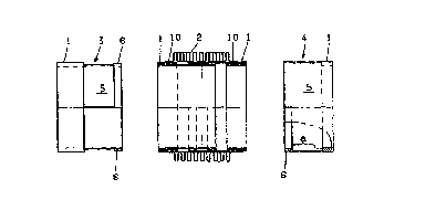
FIG. 1 an example of an axial compensator in section;
FIG. 2 an example of an outside guide element;
- 3 -

CA 02292767 1999-11-29
21223 PCT/EP98/02719 Transl. of WO 98/54507
FIG. 3 an example of an inner guide element; and
FIG. 4 a further example of an axial compensator with
several corrugated compensator tubes and a considerable slide
travel.
FIG. 1 shows a simple embodiment of an axial compensator
in section along with the corresponding guides 3 and 4. The
compensator is comprised basically of a corrugated compensator tube
2 extending between two pipe sleeves formed as weld-connector ends
1. The corrugated connector tube 2 has welded-on rings 10 for
connection with the connector ends 1. The tubular elements func-
tinning as guides 3 and 4 have adjacent the connector ends tele-
scoping inner and outer tubes 5 whose ends are formed with flange-
like spacing noses 6. The spacing noses 6 are on the outside of
the inner guide element 3 and on the inside of the outer guide
element 4. The spacing noses 6 are as better shown in FIGS. 3 and
4 aligned with each other in the tubes 5 and the gaps 7 between the
spacing noses 6 have a greater angular dimension than the
spacing noses 6 which have an angular dimension ~B. The number of
spacing noses that are set diametrally opposite each other on the
tubes 5 can be varied, axial stability increasing with the number.
In order to assemble a compensator the inner guide
element 4 is fitted into the outer guide element 3 and the two are
relatively turned until the spacing nose 6 of the outer guide
element 4 engages an abutment 11. The slide travel a is limited on
extension and contraction by the spacing noses 6 of the guide
- 4 -

CA 02292767 1999-11-29
21223 PCT/EP98/02719 Transl. of WO 98/54507
elements 3 and 4. FIG. 4 shows a further embodiment of an axial
compensator in section which for example is comprised of five
corrugated compensator tubes 2 and is intended to provide substan-
tial slide travel to compensate for length changes. To this end
pipe elements or tube sections 9 are used on all but the guide
elements 3 and 4 connected to the weld connector ends 1 and serve
not only to mount the corrugated compensator tubes 2 but also to
guide telescopingly. The idea of the spacing noses 6 defining a
slide travel a is employed in the same form.
The possibility of providing any number of corrugated
compensator tubes allows the compensator to be set up for any
necessary length change in the piping system.
The particular advantages of such an arrangement are the
reduction of the compensation force so that the piping system is
not excessively stressed.
The above-mentioned protective casing can also surround
the compensator on the outside and serve as an outside guide while
simultaneously protecting the compensator from dirt.
- 5 -

CA 02292767 1999-11-29
21223 PCT/EP98/02719 Transl. of WO 98/54507
Reference character list
1 weld-connector end
2 corrugated compensator tube
3 guide
4
guide
5 tube
6 spacing nose
7 space
8 slide travel
9 guide element
10 welded-on ring
11 abutment
a slide travel
- 6 -

Representative Drawing
A single figure which represents the drawing illustrating the invention.
Administrative Status

2024-08-01:As part of the Next Generation Patents (NGP) transition, the Canadian Patents Database (CPD) now contains a more detailed Event History, which replicates the Event Log of our new back-office solution.

Please note that "Inactive:" events refers to events no longer in use in our new back-office solution.

For a clearer understanding of the status of the application/patent presented on this page, the site Disclaimer , as well as the definitions for Patent , Event History , Maintenance Fee  and Payment History  should be consulted.

Event History

Description Date
Inactive: IPC from MCD 2006-03-12
Application Not Reinstated by Deadline 2003-05-09
Time Limit for Reversal Expired 2003-05-09
Deemed Abandoned - Failure to Respond to Maintenance Fee Notice 2002-05-09
Inactive: Cover page published 2000-02-03
Inactive: IPC assigned 2000-02-02
Inactive: First IPC assigned 2000-02-02
Inactive: Notice - National entry - No RFE 2000-01-20
Application Received - PCT 2000-01-17
Application Published (Open to Public Inspection) 1998-12-03

Abandonment History

Abandonment Date Reason Reinstatement Date
2002-05-09

Maintenance Fee

The last payment was received on 2000-11-21

Note : If the full payment has not been received on or before the date indicated, a further fee may be required which may be one of the following

  • the reinstatement fee;
  • the late payment fee; or
  • additional fee to reverse deemed expiry.

Patent fees are adjusted on the 1st of January every year. The amounts above are the current amounts if received by December 31 of the current year.
Please refer to the CIPO Patent Fees web page to see all current fee amounts.

Fee History

Fee Type Anniversary Year Due Date Paid Date
Basic national fee - small 1999-11-29
MF (application, 2nd anniv.) - small 02 2000-05-09 2000-04-19
MF (application, 3rd anniv.) - small 03 2001-05-09 2000-11-21
Owners on Record

Note: Records showing the ownership history in alphabetical order.

Current Owners on Record
HANS RATTAY
Past Owners on Record
None
Past Owners that do not appear in the "Owners on Record" listing will appear in other documentation within the application.
Documents

To view selected files, please enter reCAPTCHA code :


To view images, click a link in the Document Description column (Temporarily unavailable). To download the documents, select one or more checkboxes in the first column and then click the "Download Selected in PDF format (Zip Archive)" or the "Download Selected as Single PDF" button.

List of published and non-published patent-specific documents on the CPD .

If you have any difficulty accessing content, you can call the Client Service Centre at 1-866-997-1936 or send them an e-mail at CIPO Client Service Centre.

({010=All Documents, 020=As Filed, 030=As Open to Public Inspection, 040=At Issuance, 050=Examination, 060=Incoming Correspondence, 070=Miscellaneous, 080=Outgoing Correspondence, 090=Payment})


Document
Description 
Date
(yyyy-mm-dd) 
Number of pages   Size of Image (KB) 
Representative drawing 2000-02-02 1 4
Abstract 1999-11-28 1 52
Description 1999-11-28 9 285
Claims 1999-11-28 2 54
Drawings 1999-11-28 3 48
Reminder of maintenance fee due 2000-01-19 1 113
Notice of National Entry 2000-01-19 1 195
Courtesy - Abandonment Letter (Maintenance Fee) 2002-06-05 1 183
Reminder - Request for Examination 2003-01-12 1 112
PCT 1999-11-28 11 383