Note: Descriptions are shown in the official language in which they were submitted.
CA 02292949 1999-12-03
-1-
DESCRIPTION
APPARATUS FOR REMOVING FINE PARTICLES IN EXHAUST GAS
AND APPARATUS FOR CLEANING EXHAUST GAS
TECHNICAL FIELD
The present invention relates to an apparatus for
removing fine particles in an exhaust gas , which removes black
smoke particles contained in exhaust gases emitted from diesel
engines and various boilers, and an apparatus for cleaning an
exhaust gas.
BACKGROUND ART
An exhaust gas from a diesel engine contains nitrogen
oxides and black smoke particles ( particulate ) that are harmful
to human bodies . Among them, the black smoke particles consist
mainly of carbons. To remove the particles, various fine
particle-removing devices have already been proposed. For
example, JPA O1-77715 discloses such a device that employs a
ceramic filter of cross-flow type. In this device, an intake
path and an exhaust path for an exhaust gas are arranged in such
a relation that they cross with each other at right angle via
a partition of gas-permeable porous solid (ceramic). The black
smoke particles are captured at the partition when the
introduced exhaust gas penetrates through the partition.
JPA O1-159408, for example, also discloses a fine
particle-removing device that utilizes a ceramic filter with
a honeycomb structure. In this device, a gas-permeable porous
solid is also used as partitions that form respective cells in
the honeycomb structure. In addition, one end with respect to
CA 02292949 1999-12-03
-2-
a first group of cells and the other end with respect to a second
group of cells are closed. Then, an exhaust gas is introduced
into the second group of cells from the first group of cells
via respective partitions so as to capture the black smoke
particles at each partition.
Either of the above-mentioned conventional devices for
removing fine particles in exhaust gases is, however, a system
for filtering the black smoke particles by allowing them to
penetrate through the partition of a porous material.
Accordingly, there is a disadvantage that a resistance against
the exhaust gas flow is increased and the output of the diesel
engine is lowered. In addition, the black smoke particles
captured at the partition are finally burned up to dispose. At
this moment, another disadvantage is caused because ashes
remained after burning up may stay over the surface of the
partition and clog the filter gradually, lowering the filter
function finally, increasing the exhaust resistance further
more and lowering the output of the engine. For this reason,
adapted in the art is a method of rinsing back the black smoke
particles captured at the surface of the ceramic partition and
burning them up after transferring them to another location.
Therefore, the device disadvantageouslybecomes a larger scale.
DISCLOSURE OF INVENTION
The present invention has been made in consideration of
such the situations and has an object to provide an apparatus
for removing fine particles in an exhaust gas. The apparatus
is capable of suppressing an increase of an exhaust resistance
so as to prevent the output from lowering, and of simplifying
the apparatus by processing captured fine particles efficiently.
The present invention also provides an apparatus for cleaning
CA 02292949 1999-12-03
-3-
an exhaust gas that utilizes the apparatus for removing fine
particles.
The present invention is provided with a fine
particle-removing apparatus connected to an exhaust path for
an exhaust gas emitted from a combustion engine, for removing
fine particles contained in the exhaust gas. The apparatus
comprises a filter for capturing the fine particles contained
in the exhaust gas at partitions during the exhaust gas being
introduced into one side and exhausted from the other side of
a plurality of paths . The plurality of paths are defined by the
partitions and formed to extend in the direction of a flow of
the exhaust gas . The apparatus also comprises a fuel injection
nozzle for injecting a fuel into an exhaust gas intake portion
of the filter, and an ignition means for igniting the fuel
injected from the fuel injection nozzle.
In the present invention, once the exhaust gas is
introduced into each of the plurality of narrow paths that
extend in the direction of the gas flow, the exhaust gas travels
within the paths while the gas is disturbed to flow by the
partitions that define the paths. In this process, the fine
particles contained in the exhaust gas are captured at the
surfaces of the partitions, which are in parallel to the
direction in which the paths extend. The fuel is injected into
the exhaust gas intake portion of the filter from the fuel
injection nozzle. When the ignition means ignites the fuel,
flames are carried by the exhaust gas flow and extend over each
wall of the paths, burning up the fine particles captured at
the walls of the paths. Ashes remained after burning are ejected
to the outside of the filter in accordance with the exhaust gas
f low .
As described above, according to the present invention,
CA 02292949 1999-12-03
-4-
the filter forms a plurality of paths extending in the direction
of the exhaust gas flow. Then, the exhaust gas is introduced
into one side and emitted from the other side of the paths . In
this process, the fine particles are captured at the walls of
the paths. Therefore, the exhaust gas can flow extremely
smoother and the exhaust resistance can be suppressed
sufficiently lower than the conventional systems that filter
the gas with porous materials, thereby preventing the output
from lowering. The exhaust gas is disturbed slightly to flow
during it travels through the narrow paths . As the result , the
fine particles in the exhaust gas can be captured well at the
partition walls of the paths. In addition, the ashes, which
remains after burning the fine particles captured at the
partition walls, are smoothly ejected to the outside of the
filter and do not stay over the filter surfaces. Thus,
maintenance is hardly required and the apparatus can be
simplified. Further, if the same light oil as a fuel for the
diesel engine is used as the fuel for burning the fine particles ,
for example, a particular fuel supply is not required and
maintenance becomes much easier.
If the filter is made of gas-permeable porous solid, the
exhaust gas, which travels along with turbulent flows in the
narrow paths, flows so as to penetrate even into the inside of
the partitions. Thus, the fine particles contained in the
exhaust gas can be captured further effectively at the partition
walls.
The filter may be definitely formed to have plural paths
extending in the direction of the exhaust gas flow and arranged
in the direction perpendicular to the exhaust gas flow. The
plural paths are defined by plural partitions, which consist
of porous ceramic plates and arranged in parallel, and have
CA 02292949 1999-12-03
-5-
substantially rectangular cross sections . More preferably, the
filter may include plural stages of filter units. In this case,
porous ceramic partitions in adjacent filter units may be
arranged to cross at right angle to each other. This arrangement
enables to increase the effect of providing the exhaust gas with
turbulent flows so as to capture the fine particles further
effectively.
Further comprising a means for introducing a combustion
promoting gas such as an air into the exhaust gas intake portion
of the filter, as well as applying a combustion promoting agent
on at least parts of the partition surfaces of the filter, may
improve a combustion efficiency during the fine particles are
burned.
Burning the fine particles may be performed
intermittently when a predetermined amount of the particles is
accumulated over the partition surfaces of the filter. In this
case, the apparatus may perform a burning operation when a
temperature of the filter drops to a predetermined value by
further comprising a temperature sensor for detecting a
temperature of the filter and a control means , for example . The
control means allows the fuel injection nozzle to inject the
fuel and the ignition means to perform an igniting operation
if the temperature sensor detects a temperature lowered down
to a first temperature. The control means also halts the fuel
injection nozzle to inject the fuel if the temperature sensor
detects a temperature elevated up to a second temperature higher
than the first temperature.
In case where the above-mentioned filter is disposed in
an exhaust path of a diesel engine, combining the filter with
an exhaust gas return control device for returning the exhaust
gas from the exhaust path to an intake path of the diesel engine
CA 02292949 1999-12-03
-6-
can configure an exhaust gas cleaning apparatus. Thus
conf figured apparatus can prevent the black smoke from returning
into the intake portion of the engine and reduce NOx at the same
time. Arranging a catalyzing device at the exhaust portion of
the filter may further clean the exhaust gas effectively.
BRIEF DESCRIPTION OF DRAWINGS
Fig. 1 is a diagram illustrating an exhaust system of a
diesel engine to which a fine particle-removing apparatus
according to an embodiment of the present invention is adaptive.
Figs . 2A and 2B are squint views showing the exterior and
interior of the apparatus.
Fig. 3 is a control system diagram of the apparatus.
Fig . 4 is a timing chart for explaining operations of the
apparatus.
Fig. 5 is a diagram illustrating an example of a ceramic
partition in the apparatus.
Fig. 6 is a diagram showing a fuel injection system
according to another embodiment of the present invention.
Fig. 7 is a squint view illustrating a filter according
to another embodiment of the present invention.
Fig. 8 is a squint view illustrating a filter according
to a further embodiment of the present invention.
Fig. 9 is a diagram illustrating an exhaust gas cleaning
apparatus according to a further embodiment of the present
invention.
Fig. 10 is a squint view illustrating a configuration of
a filter according to the embodiment.
Figs. 11A and 11B are a front and cross sectional views
of a filter unit for use in the filter of the embodiment .
Fig. 12 is a cross sectional view illustrating a part of
CA 02292949 1999-12-03
the filter.
Fig. 13 is a timing chart for explaining a burning control
operation of the filter in the exhaust gas cleaning apparatus .
Fig. 14 is a block diagram showing an arrangement of a
controller for performing a burning control to the filter.
Fig. 15 is a block diagram showing an arrangement of a
pump controller in the burning control to the filter.
Fig. 16 is a waveform diagram showing an operation of the
pump controller.
Fig. 17 is a waveform diagram showing an operation of the
pump controller.
BEST MODE FOR CARRYING OUT THE INVENTION
Preferred embodiments of the present invention will be
described below with reference to the drawings.
Fig. 1 is a diagram illustrating an exhaust system of a
diesel engine to which an apparatus for removing fine particles
in an exhaust gas of the present invention is adapted.
An exhaust gas from a diesel engine 1 passes through a
sub muffler 3 and main muffler 4 in the process of passing through
an exhaust pipe 2. In this embodiment, a fine particle-removing
device 5 is interposed between the sub muffler 3 and the main
muffler 4 , and removes black smoke particles contained in the
exhaust gas.
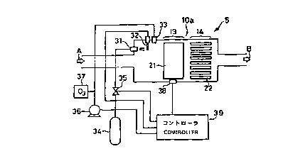
Figs. 2 and 3 are diagrams showing the fine particle-
removing device 5 in detail, in which Fig. 2A is an exterior
squint view, Fig. 2B is a squint view illustrating an interior
state, and Fig. 3 is a system diagram.
As shown in Fig. 2A, the fine particle-removing device
5 consists mainly of a front cover 12 with an inlet 11 to which
an unfinished exhaust gas A that has not been finished to remove
CA 02292949 1999-12-03
_g_
fine particles is introduced; a filter l0a for removing the fine
particles from the exhaust gas; and a rear cover 16 with an
outlet 15 for disposing a finished exhaust gas B. The ffilter
l0a consists of a first filter unit 13 and a second filter unit
14 arranged in the direction of the exhaust gas flow.
The first filter unit 13 and the second filter unit 14
consist of a plurality of first partitions 21 and a plurality
of second partitions 22 that are arranged with a predetermined
interval in the direction of the exhaust gas flow (A, B) as shown
in Fig. 2A. The first and second partitions 21 and 22 are of
porous ceramic plates , and more definitely gas -permeable porous
plates of cordierite series. The first and second partitions
21 and 22 are arranged more than one in the direction
perpendicular to the direction of the exhaust gas flow
interposing respective predetermined intervals (e. g.
intervals of 5-30 mm) : the first partitions 21 a.n the lateral
direction, and the second partitions 22 in the longitudinal
direction. In the first filter unit 13 , narrow paths 23 , which
are defined by the partitions 21 and extend in the direction
of the exhaust gas flow, are arranged more than one in the lateral
direction perpendicular to the direction of the exhaust gas flow.
Similarly, in the second filter unit 14, narrow paths 24, which
are defined by the partitions 22 and extend in the direction
of the exhaust gas flow, are arranged more than one in the
longitudinal direction perpendicular to the direction of the
exhaust gas flow. The paths 23 and 24 , which have substantially
rectangular cross sections intersecting to each other at right
angle, both extend in parallel to the direction of the exhaust
gas flow. The black smoke particles are captured at both
surfaces of the partitions 21 and 22 that define these paths
23 and 24.
CA 02292949 1999-12-03
-9-
Mounted on the front cover 12 are a fuel injection nozzle
31, an ignition device 32 and a combustion promoting gas
introduction nozzle 33. A control system for these will be
described with reference to Fig. 3. A butane gas can be employed,
for example, as the fuel for burning the black smoke particles
captured at the surfaces of the ceramic partitions 21 and 22.
In this case, the butane gas stored in a bin 34 is injected into
exhaust gas intake portions of the filter units 13 and 14 from
the fuel injection nozzle 31 through a valve 35. The ignition
device 32 is arranged at the injection position and the burning
promotion gas introduction nozzle 33 is located at a further
rear stage. The combustion promoting gas is typically an air
supplied from a compressor 36, and ozone is preferably added
slightly from an ozone generator 37 to increase a combustion
efficiency. Such the gas is supplied from the nozzle 33 to the
exhaust gas intake portions of the filter units 13 and 14.
In proximity to the ceramic partition 21, a temperature
sensor 38 is disposed to detect a temperature of the partition
21. The temperature detection result is introduced into a
controller 39. The controller 39 controls the valve 35, ignition
device 32 and compressor 36 based on the temperature detection
result, respectively.
An operation of thus configured fine particle-removing
device will be described next.
The temperature of the exhaust gas emitted from the diesel
engine 1 lowers in the process of passing through the sub muffler
3 and main muffler 4 and exhibits approximately 400° C - 600° C
at the rear stage of the sub muffler 3. Once the exhaust gas
is introduced into the inside of the fine particle-removing
device 5 through the inlet 11 of the device 5 , it passes through
first each path 23 of the first filter unit 3 and then each path
CA 02292949 1999-12-03
-10-
24 of the second filter unit 14. The exhaust gas is disturbed
to flow in the process of passing through the narrow paths 23
and 24 , and the black smoke particles contained in the exhaust
gas attach to the surfaces of the partitions 21 and 22, since
the filter units 13 and 14 are composed of the porous ceramic
partitions 21 and 22. Fluid resistances at the narrow paths 23
and 24 are extremely low, however, since they extend in the
direction of the exhaust gas flow. Therefore, the exhaust gas,
which remains after the black smoke particles are removed, can
be smoothly ejected from the outlet 15.
Fig. 4 is a timing chart for explaining the combustion
control of the device 5. When the temperature detected at the
temperature sensor 38 is equal to or below a first temperature
(e. g. 700°C), the controller 39 opens the valve 35, operates
the compressor 36, and turns the ignition device 32 on. As a
result, the fuel or the butane gas is ignited, and the black
smoke particles attached over the surfaces of the ceramic
partitions 21 and 22 are burned, while the combustion is
promoted by supplying the combustion promoting gas . The ashes
remained after combustion are ejected along with the exhaust
gas through the outlet 15 . Thus , the ceramic partitions 21 and
22 are prevented from clogging.
When the temperature of the ceramic partition 21 elevated
up to a second temperature (e.g. 1000° C) after the continuous
combustion, the controller 39 closes the valve 35 and put off
the compressor 36 to halt the combustion operation. As a result,
the temperature inside the device 5 is prevented from elevating
excessively. When the temperature lowers down to the first
temperature again, the same operation will be repeated.
A combustion-promoting agent 41 such as platinum may be
effectively applied on at least parts of the ceramic partitions
CA 02292949 1999-12-03
-11-
-~21 and 22 as shown in Fig.5, for example. Thereby further
promoting the combustion at the surfaces of the partitions 21
and 22 and enabling to process the black smoke particles more
efficiently. A liquid fuel such as ethanol may be employed as
the fuel instead of gaseous fuel such as the butane gas . In this
case, a liquid fuel 43 stored in a tank 42 may be supplied to
the fuel injection nozzle 31 by lifting it up with a pump 44
as shown in Fig. 6.
Fig. 7 shows a configuration of a filter lOb according
to another embodiment. In this embodiment, first filter units
13 and second filter units 14 are alternately arranged four
stages in total in the direction of the exhaust gas flow
interposing a predetermined gap therebetween. Porous ceramic
partitions 21 of the first filter units 13 and porous ceramic
partitions 22 of the second filter units 14 are arranged one
or more in the directions crossing with each other at right angle .
Accordingly, the plural paths 23 and 24, which cross with each
other at right angle and have substantially rectangular cross
sections , are linked in the multiplexed form along the exhaust
gas flow.
Thus, the passing exhaust gas becomes a turbulent flow,
resulting in an increased amount of fine particles absorbed on
the partitions by combining the filter units in such the
multi-stage that the partitions which define the paths in
adjacent units to cross with each other at right angle. That
is, the efficiency for removing fine particles becomes much
higher. In addition, the increase of the exhaust resistance can
be ignored since the paths 23 and 24 in respective filter units
are in parallel to the direction of the exhaust gas flow.
Fig. 8 shows a configuration of a filter lOc according
to a further embodiment. In this embodiment, the filter lOc
CA 02292949 1999-12-03
-12-
consists of a single porous ceramic block 52. The block 52
includes many paths 51 that are defined by ceramic partitions
53 to extend in the direction of the exhaust gas flow and are
processed to arrange one or more both in the longitudinal and
lateral directions, respectively. In this case, the paths 51
may be effectively shaped to be longitudinally long rectangular
at gas intake portions and laterally long rectangular at gas
exhaust portions.
The reason why device 5 is located at the front stage of
the sub muffler 4 as shown in Fig. 1 is based on that a temperature
of the exhaust gas at that location is about 600° C and is
convenient . The device of the present invention , however , can
also be located, for example, inside the sub muffler 3 or at
the rear stage of main muffler 4, needless to say.
Fig. 9 shows a configuration of an exhaust gas cleaning
apparatus according to a further preferred embodiment of the
present invention, in which the fine particle-removing device
5 of the present invention is fabricated. The apparatus is of
the diesel engine 1 that includes an EGR device (Exhaust Gas
Return device) and a catalyzing device. A filter lOd, which is
contained in the body of the fine particle-removing device 5 ,
includes a gas intake pipe 100 connected to an exhaust pipe 101
of the diesel engine 1 through a bellows gas pipe 102 . The filter
lOd also includes an exhaust pipe 104 connected, through a
bellows gas pipe 104 , to a catalyzing device 105 for removing
harmful gases. The catalyzing device 105 is definitely
configured with catalysts capable of removing CO, HC and NOx.
As shown in Fig. 10, the filter lOd in this embodiment
has three stages of filter units 92 , 93 and 94 that are arranged
within one filter container 91. The three stages of filter units
92 , 93 and 94 consist of porous ceramic blocks in the form of
CA 02292949 1999-12-03
-13-
oval columns . As shown in Figs . 10 and 11, each of the filter
units 92, 93 and 94 has a plurality of paths 202 that are defined
by porous ceramic partitions 201 and extend in the direction
of the exhaust gas flow. Fig. 11B shows a cross section of one
of the units sectioned with the horizontal plane passing through
the center of the unit (cross section at the I-I' line shown
in Figs. 10 and 11A). The partitions 201 are linked with each
other at their outer circumferential portions, and are also
linked laterally with each other at the central portion and
optionally upper and lower portions.
The three stages of filter units 92, 93 and 94 are
positioned with not-depicted positioning members, and then
sandwiched between upper and lower stainless covers 203 and 204
to fabricate integrally so as to be arranged with a certain
interval in the direction of the exhaust gas flow. A cushion
material such as ceramic fibers may preferably be wounded around
each of the filter units 92, 93 and 94 to avoid any damages from
vibrations.
As shown in Fig. 10, a front cover 205 for forming a
combustion chamber is disposed at the front stage of the filter
units 92, 93 and 94. A porous combustion tube 95 is arranged
within the front cover 205 so that its axis intersects with the
direction of the exhaust gas flow at right angle. Spray nozzles
95a and 95b are disposed at both ends of the combustion tube
95. Spark plugs 97a, 97b and ignition heaters 98a, 98b are
arranged adjacent to the spray nozzles 96a and 96b. The spark
plug 97a and ignition heater 98a are surrounded by a protection
wall 99a, and the spark plug 97b and ignition heater 98b by a
protection wall 99b,respectively. Regions surrounded by the
protection walls 99a and 99b are hardly affected from the
exhaust gas flow, and mixed gases sprayed from the spray nozzles
CA 02292949 1999-12-03
-14-
96a and 96b may stay in the regions with a high density to realize
an environment suitable for igniting. Fig. 12 shows a cross
sectional view of the ignition heater 98a and its periphery.
The ignition heater 98a comprises a holder 221 for fixing, a
glow 222 supported by the holder 221, and a ceramic tube 223
with a rich permeability for surrounding the periphery of the
glow 222. When a switch for the glow 222 is turned on and the
ceramic tube 223 at its periphery is heated, a fuel permeated
into the ceramic tube 223 is vaporized and then ignited exactly
with sparks from the spark plug 97a.
As shown in Fig. 9, in order to configure an EGR device
110 , a part of the exhaust gas , which flows through an exhaust
pipe 103 of the filter lOd, is fed back via a return path 108
to an intake pipe 107 located between an air cleaner 257 and
the diesel engine 1. Interposed into a midpoint of the return
path 108 is an EGR valve 106 which controls a return amount of
the exhaust gas or an inert gas so as to lower a combustion
temperature in the diesel engine 1 to reduce NOx.
A temperature detector 251 detects a temperature of the
ceramic in the filter lOd and sends the detected value to a
controller 252. A fuel such as light oil stored in a fuel tank
254 is supplied to each of spray nozzles 96a and 96b by a pump
255. Another pump 256 supplies an air to each of the spray nozzles
96a and 96b. A battery 253 supplies necessary power to the spark
plugs 97a, 97b, ignition heaters 98a, 98b and controller 252.
An operation of thus configured exhaust gas reducing
device will be described next with reference to a timing chart
of Fig. 13.
First, the diesel engine 1 is started at time tl. Then,
the switch for the glow 222 is turned on at t2 later than tl
by T1 ( a . g . 1 minute ) . Thereaf ter , the fuel supplying pump 25 5
CA 02292949 1999-12-03
-15-
and the air supplying pump 256 are put on at t3 later than t2
by T2 (e.g. 10 seconds) to introduce the mixed gas into the
combustion chamber so as to prepare an ignition environment.
At this moment, an ignition by red heat of the glow 222 can be
performed. To ignite exactly, however, ignitions by the spark
plugs 97a and 97b are used to start the combustion operation.
The temperature in the filter lOd elevates with the combustion
inside the combustion tube 95 and the black smoke attached over
the surfaces of the partitions 201 is burned up and removed.
Once the combustion operation is started, heating by the glow
222 becomes unnecessary. Therefore, the switch for the glow 222
is turned off, for example, after confirming the combustion
operation at t4 later than t3 by T3 (e.g. 30 seconds). The
fuel-supplying pump 255 is put off when the temperature detector
251 detects that the ceramic temperature of the filter lOd
reaches up to 900°C at t5. The air-supplying pump 256 for,
however, continues to maintain its on-state. Thus, oxygen
required for burning is continuously supplied, and the
combustion at the surface of the partition 201 is continued.
The exhaust gas gradually lowers the surface temperature of the
partition 201, however, because halting the fuel supply has
stopped the combustion inside the combustion tube 95.
When the temperature detector 251 detects that the
ceramic temperature of the filter lOd lowers down to 730° C at
t6, the switch for the glow 222 is turned on again, and the fuel
supplying pump 255 is put on at t7 later than t6 by T2. The
ignition operation with sparks is made, and the switch for the
glow 222 is turned off at t8 later than the time of supplying
the fuel by T3. When the temperature detector 251 detects that
the ceramic temperature reaches to 900° C at t9 , the fuel-
supplying pump 255 is put off . Similar operations are repeated
CA 02292949 1999-12-03
-16-
hereaf ter .
Fig. 14 shows an arrangement of a combustion control
circuit 300 contained in the controller 252 for performing the
above combustion control. The output from the temperature
detector 251 is fed into two comparators 301 and 302. These
comparators 301 and 302 determine a level of the input
temperature signal with a low-level voltage LV (e. g.
corresponds to the first temperature, 730°C) and high-level
voltage HV ( a . g . corresponds to the second temperature , 900° C )
as reference voltages, respectively. When the level of the
temperature signal lowers below the low-level voltage LV, the
output of the comparator 301 becomes "L" which in turn sets a
flip-flop 303 to exhibit the Q-output = "H" . On the other hand,
when the level of the temperature signal elevates above the
high-level voltage HV, the output of the comparator 302 becomes
"H" which in turn resets the flip-flop 303 to exhibit the
Q-output = "L" . A start-reset signal is fed to the reset input
of the flip-flop 303 through a NOR gate G1 in order to inhibit
the combustion control operation during a battery voltage is
lowed at the time of starting the engine . The start-reset signal
exhibits "H" within a time period of T1 set by a timer 304 after
an engine start signal is input . The glow 222 is turned on during
a time period of T2 + T3 set by a timer 305 after the rise of
the Q-output of the flip-flop 303. A NAND gate G2 outputs a signal
that is formed by delaying only the rise of the Q-output of the
flip-flop 303 by the time period T2 set by a timer 306 in order
to control the fuel supplying pump 255. The output Q of a
flip-flop 307 is set by a first rise of the NAND gate G2 , and
thereafter maintains its on-state during the engine operation.
The output Q drives the air-supplying pump 256. The output of
the NAND gate G2 is also input to a trigger generator 308 that
CA 02292949 1999-12-03
-17-
allows the spark plugs 97a and 97b to ignite.
Supply amounts of the fuel and air are preferably those
that correspond to revolutions of the engine 1 . For this reason,
a pump control circuit 400 is fabricated in the controller 252
as shown in Fig. 15. An output signal detected at a microphone
401, which corresponds to intermittent explosive sounds as
shown in Fig. 16(a) , is amplified by an amplifier 402. The output
signal from the amplifier 402 is shaped by a waveform shaping
circuit 403 into a pulse signal as shown in Fig. 16 ( b ) . A
frequency-voltage converter (F/V converter) 404 converts a
frequency of the output pulse from the waveform shaping circuit
403 into a voltage. A PWM amplifier 405 outputs a signal with
a pulse width corresponding to the output voltage from the F/V
converter 404 . Thus , control pulses with different pulse widths
in four-stage according to frequencies can be obtained as shown
in Fig. 17, for example.
In this exhaust gas-reducing device, the filter lOd can
solve the disadvantage of returning the black smoke to the
intake portion, which is problematic in the EGR device. As a
result, the EGR device 110 can work efficiently and the black
smoke can be effectively reduced along with NOx. In addition,
arranging the catalyzing device 105 at the rear stage of the
filter lOd can further reduce CO, HC and NOx, and this is
extremely effective for the exhaust gas control.
As described above , according to the present invent ion ,
the filter forms a plurality of paths extending in the direction
of the exhaust gas flow. Then, the exhaust gas is introduced
into one side and emitted from the other side of the paths . In
this process , the fine particles are captured at the walls of
the paths. Therefore, the exhaust gas can flow extremely
smoother and the exhaust resistance can be suppressed
CA 02292949 1999-12-03
- 18-
sufficiently lower than the conventional systems that filter
the gas with porous materials, thereby preventing the output
from lowering. In addition, the ashes, which remains after
burning the fine particles captured at the partition walls, are
smoothly ejected to the outside of the filter and do not stay
over the filter surfaces. Thus, the apparatus can be simplified.