Language selection

Search

Patent 2293044 Summary

Third-party information liability

Some of the information on this Web page has been provided by external sources. The Government of Canada is not responsible for the accuracy, reliability or currency of the information supplied by external sources. Users wishing to rely upon this information should consult directly with the source of the information. Content provided by external sources is not subject to official languages, privacy and accessibility requirements.

Claims and Abstract availability

Any discrepancies in the text and image of the Claims and Abstract are due to differing posting times. Text of the Claims and Abstract are posted:

  • At the time the application is open to public inspection;
  • At the time of issue of the patent (grant).
(12) Patent Application: (11) CA 2293044
(54) English Title: VEHICLE INNER TUBE WITH MEANS FOR PROTECTION AGAINST PIERCING OF POINTED OBJECTS
(54) French Title: CHAMBRE A AIR DE VEHICULE AVEC MOYEN DE PROTECTION CONTRE LES PERFORATIONS
Status: Deemed Abandoned and Beyond the Period of Reinstatement - Pending Response to Notice of Disregarded Communication
Bibliographic Data
(51) International Patent Classification (IPC):
  • B60C 5/08 (2006.01)
  • B60C 5/00 (2006.01)
  • B60C 19/12 (2006.01)
(72) Inventors :
  • HSU, SHUT CHEN (Taiwan, Province of China)
(73) Owners :
  • SHUT CHEN HSU
(71) Applicants :
  • SHUT CHEN HSU (Taiwan, Province of China)
(74) Agent: NORTON ROSE FULBRIGHT CANADA LLP/S.E.N.C.R.L., S.R.L.
(74) Associate agent:
(45) Issued:
(22) Filed Date: 1999-12-22
(41) Open to Public Inspection: 2001-06-22
Examination requested: 2000-03-27
Availability of licence: N/A
Dedicated to the Public: N/A
(25) Language of filing: English

Patent Cooperation Treaty (PCT): No

(30) Application Priority Data: None

Abstracts

English Abstract


A vehicle inner tube, which includes an inflatable tube
formed of a plurality of air balls, the inflatable tube having an
air chamber defined on the inside, two sets of curved grooves
spirally arranged at two opposite side walls thereof around an air
chamber, and a plurality of insertion slots spirally arranged
around the curved grooves through the two opposite side walls,
and a plurality of breaker members and side bumper members
respectively mounted in the insertion slots and curved grooves at
the inflatable tube, the breaker members and side bumper
members each including a flexible base pad formed of a big
number of air balls, and a breaker adhered to the base pad at one
side.


Claims

Note: Claims are shown in the official language in which they were submitted.

6
What the invention claimed is:
1. A vehicle inner tube comprising:
an inflatable tube formed of a plurality of air balls, said
inflatable tube comprising an air chamber defined on the inside,
two sets of curved grooves spirally arranged at two opposite side
walls thereof around said air chamber, and a plurality of
insertion slots spirally arranged around said curved grooves
through the two opposite side walls of said inflatable tube;
a plurality of breaker members respectively mounted in
said insertion slots, said breaker members each comprising a
flexible base pad formed of a big number of air balls, and a
breaker adhered to said base pad at one side; and
a plurality of side bumper members respectively
mounted in said curved grooves, said side bumper members each
comprising a flexible base pad formed of a big number of air
balls, and a breaker adhered to said base pad at one side.
2. A vehicle inner tube comprising:
an inflatable tube formed of a plurality of air balls, said
inflatable tube comprising an air chamber defined on the inside,
and two sets of curved grooves spirally arranged at two opposite
side walls thereof around said air chamber; and
a plurality of side bumper members respectively
mounted in said curved grooves, said side bumper members each
comprising a flexible base pad formed of a big number of air
balls, and a breaker adhered to said base pad at one side.

7
3. A vehicle inner tube comprising:
an inflatable tube formed of a plurality of air balls, said
inflatable tube comprising an air chamber defined on the inside,
and a plurality of insertion slots spirally arranged around said air
chamber through the two opposite side walls of said inflatable
tube; and
a plurality of breaker members respectively mounted in
said insertion slots, said breaker members each comprising a
flexible base pad formed of a big number of air balls, and a
breaker adhered to said base pad at one side.

Description

Note: Descriptions are shown in the official language in which they were submitted.


CA 02293044 1999-12-22
1
VEHTCLE INNER TUBE WITH MEANS FO_R_ PROTECTION
The present invention relates to a vehicle inner tube for
5 a motor vehicle, and more particularly to such a vehicle inner
tube which has protective breaker means for protection against
piercing of an external pointed object.
Regular motorcycle and automobile tires do not have an
inner tube. When a pointed object pierced the tire of a motor
10 vehicle, air does not immediately leak out. However, if the
motor vehicle keeps running for a certain length of time after
piercing of a pointed object through one tire thereof, the tire may
explode, causing a catastrophe. In order to eliminate this
problem, "high-speed" tires are developed. A "high-speed" tire
15 is made of elastic material of high density. When pierced by a
pointed object, the tire does not leak immediately, and the car
driver has sufficient time to repair the tire. However, because
this structure of tire does not leak immediately when pierced by a
pointed object, the car driver may not find the problem before an
20 accident occurs.
SUMMARY OF THE INVENTION
The present invention has been accomplished under the
circumstances in view. According to one embodiment of the
present invention, the vehicle inner tube comprises an inflatable
25 tube formed of a plurality of air balls, the inflatable tube having

CA 02293044 1999-12-22
2
an air chamber defined on the inside, two sets of curved grooves
spirally arranged at two opposite side walls thereof around an air
chamber, and a plurality of insertion slots spirally arranged
around the curved grooves through the two opposite side walls,
and a plurality of breaker members and side bumper members
respectively mounted in the insertion slots and curved grooves at
the inflatable tube, the breaker members and side bumper
members each including a flexible base pad formed of a big
number of air balls, and a breaker adhered to the base pad at one
side. In an alternate form of the present invention, the curved
grooves and the side bumper members are eliminated. In
another alternate form of the present invention, the insertion
slots and the breaker members are eliminated.
]3RIEF DESCRIPTION OF THE DRAWINGS
Figure 1 is a side view of an inflatable tube for a vehicle
inner tube according to the present invention.
Figure 2 is a cross sectional view of the inflatable tube
shown in Figure 1.
Figure 3 illustrates a breaker member and a side bumper
member for a vehicle inner tube according to the present
invention.
Figure 4 is a schematic drawing showing the installation
of breaker members and side bumper members in the insertion
slots and curved grooves at the inflatable tube according to the
present invention.

CA 02293044 1999-12-22
3
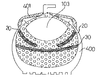
Figure 5 is a sectional view showing the vehicle inner
tube mounted within an outer tire according to the present
invention.
Figure 6 is a sectional view showing the vehicle inner
tube mounted within an outer tire and fastened to a metal wheel
frame according to the present invention.
Figure 7 is similar to Figure 6 but showing the vehicle
inner tube inflated.
Figure 8 shows the status before inflation and the status
after inflation of an alternate form of the vehicle inner tube
according to the present invention before.
Figure 9 shows the status before inflation and the status
after inflation of another alternate form of the vehicle inner tube
according to the present invention before.
DET TT.FD .S('RTPTION OF THE P FFFRRFn FMRnWn~~~rr
Referring to Figures 1 and 2, a vehicle inner tube is
shown comprised of an inflatable tube 10 formed of a big number
of air balls, having an air chamber 103 defined on the inside, two
sets of curved grooves 101 spirally arranged at its two opposite
side walls around its axial center, and a plurality of insertion
slots 102 spirally arranged around the curved grooves 101
through its two opposite side walls.
Figure 3 illustrates a breaker member 30 and a side
bumper member 20 constructed according to the present
invention. The breaker member 30 and the side bumper

CA 02293044 1999-12-22
4
member 20 each are comprised of a flexible base pad 202 or 302
formed of a big number of air balls, and a breaker 201 or 301
adhered to the base pad 202 or 302 at one side.
Referring to Figures from 4 through 7, breaker members
5 30 and side bumper members 20 are respectively inserted into the
insertion slots 102 and grooves 101 at the inflatable tube 10 to
protect the air chamber 103 against piercing of pointed objects.
After installation of the breaker members 30 and the side bumper
members 20 in the inflatable tube 10, the inflatable tube 10 is
10 mounted in an outer tire 400 (see Figure 5), and then a metal
wheel frame 401 is fastened to the outer tire 400 and the
inflatable tube 10 (see Figure 6). When installed, compressed
air is pumped into the air chamber 103 to inflate the inflatable
tube 10 (see Figure 7). When inflated, the breaker members 30
15 and side bumper members 20 are stretched outwards, causing the
distance between the breaker members 30 and the side bumper
members 20 to be relatively reduced, therefore, the air chamber
103 is well protected by the breaker members 30 and the side
bumper members 20 against piercing of pointed objects.
20 Because the inflatable tube 10 is formed of a big number of air
balls joined together with an air chamber defined in it, its has a
certain wall thickness and strong spring power. If a pointed
object is pierced through the outer tire 400 into the inflatable
tube 10, the air chamber 103 and the metal wheel frame 401 are
25 well protected by the breaker members 30 and the side bumper

CA 02293044 1999-12-22
5
members 20 against the pointed object, therefore the air chamber
103 can be maintained in an air tight condition.
Figure 8 shows an alternate forms of the present
invention. According to this embodiment, the inflatable tube
5 10 comprises an air chamber 103 defined on the inside, two sets
of curved grooves 101 spirally arranged at its two opposite side
walls around its axial center, and a plurality of side bumper
members 20 respectively inserted into the grooves 101. When
inflated, the side bumper members 20 are overlapped on one
10 another to protect the air chamber 103.
Figure 9 shows another alternate forms of the present
invention. According to this embodiment, the inflatable tube
10 comprises an air chamber 103 defined on the inside, a
plurality of insertion slots 102 spirally arranged around the
15 insertion slots 101 through its two opposite side walls, and a
plurality of breaker members 30 respectively inserted into the
insertion slots 102 to protect the air chamber 103 against
piercing of pointed objects.
It is to be understood that the drawings are designed for
20 purposes of illustration only, and are not intended for use as a
definition of the limits and scope of the invention disclosed.

Representative Drawing
A single figure which represents the drawing illustrating the invention.
Administrative Status

2024-08-01:As part of the Next Generation Patents (NGP) transition, the Canadian Patents Database (CPD) now contains a more detailed Event History, which replicates the Event Log of our new back-office solution.

Please note that "Inactive:" events refers to events no longer in use in our new back-office solution.

For a clearer understanding of the status of the application/patent presented on this page, the site Disclaimer , as well as the definitions for Patent , Event History , Maintenance Fee  and Payment History  should be consulted.

Event History

Description Date
Inactive: IPC from MCD 2006-03-12
Application Not Reinstated by Deadline 2002-12-23
Time Limit for Reversal Expired 2002-12-23
Deemed Abandoned - Failure to Respond to Maintenance Fee Notice 2001-12-24
Inactive: Cover page published 2001-06-22
Application Published (Open to Public Inspection) 2001-06-22
Letter Sent 2000-04-17
All Requirements for Examination Determined Compliant 2000-03-27
Request for Examination Received 2000-03-27
Request for Examination Requirements Determined Compliant 2000-03-27
Inactive: IPC assigned 2000-02-07
Inactive: IPC removed 2000-02-07
Inactive: IPC assigned 2000-02-07
Inactive: First IPC assigned 2000-02-07
Inactive: Filing certificate - No RFE (English) 2000-01-20
Filing Requirements Determined Compliant 2000-01-20
Application Received - Regular National 2000-01-20

Abandonment History

Abandonment Date Reason Reinstatement Date
2001-12-24

Fee History

Fee Type Anniversary Year Due Date Paid Date
Application fee - small 1999-12-22
Request for examination - small 2000-03-27
Owners on Record

Note: Records showing the ownership history in alphabetical order.

Current Owners on Record
SHUT CHEN HSU
Past Owners on Record
None
Past Owners that do not appear in the "Owners on Record" listing will appear in other documentation within the application.
Documents

To view selected files, please enter reCAPTCHA code :


To view images, click a link in the Document Description column. To download the documents, select one or more checkboxes in the first column and then click the "Download Selected in PDF format (Zip Archive)" or the "Download Selected as Single PDF" button.

List of published and non-published patent-specific documents on the CPD .

If you have any difficulty accessing content, you can call the Client Service Centre at 1-866-997-1936 or send them an e-mail at CIPO Client Service Centre.


Document
Description 
Date
(yyyy-mm-dd) 
Number of pages   Size of Image (KB) 
Representative drawing 2001-06-22 1 13
Cover Page 2001-06-22 1 40
Drawings 1999-12-22 9 231
Claims 1999-12-22 2 50
Description 1999-12-22 5 173
Abstract 1999-12-22 1 22
Filing Certificate (English) 2000-01-20 1 164
Acknowledgement of Request for Examination 2000-04-17 1 178
Reminder of maintenance fee due 2001-08-23 1 116
Courtesy - Abandonment Letter (Maintenance Fee) 2002-01-21 1 182