Note: Descriptions are shown in the official language in which they were submitted.
CA 02293218 1999-12-10
WO 98/58825 PCT/US98112543
r
WINDOW WIPER MOTOR SYSTEM FOR AN AUTOMOTIVE VEHICLE
This application is a continuation-in-part of U.S. Serial No.08/431,149
entitled
"Control System For An Automotive Vehicle Multi-Functional Apparatus," filed
on
April 28, 1995, which is incorporated by reference herewithin.
BACKGROUND OF THE INVENTION
This invention relates generally to window wipers and specifically to a window
wiper motor system for an automotive vehicle.
Almost all automotive vehicles have a single or a pair of windshield wiper
assemblies. These assemblies traditionally include rubber wiper blades mounted
upon
claw brackets. These claw brackets are pivotably attached to wiper arms
mounted
upon rotating shafts. The shafts are either directly driven by electric motors
or
driven by a single electric motor which actuates a series or parallel-coupled
four bar
linkage mechanism. It is further known to provide a wiper system, in
combination
with a wash device, to clean headlamps for automotive vehicles.
It is also common to employ a window wiper assembly for cleaning rear
windows of automotive vehicles. Typically, these types of rear window wiper
assemblies include a wiper blade mounted upon a bracket which is coupled to a
wiper
arm. The wiper arm is attached to a wiper shaft rotatably driven in a cyclical
oscillating manner by a helical gear. A reversible, fractional horsepower,
direct
current electric motor serves to actuate the helical gear through an armature
shaft-
mounted worm gear enmeshed therewith. This type of rear window wiper
arrangement is usually mounted upon a pivoting liftgate of a minivan, station
wagon,
sport-utility vehicle or the like. One such example is disclosed in U.S.
Patent No.
5,519,258 entitled "System and Method for Controlling Vehicle Lift Gate Window
Wiper" which issued to Stroven et al. on May 21, 1996.
Some conventional vehicles also provide a rear window release lock or latch,
actuated by a solenoid, which can be unlocked to allow for upward pivotal
movement
of a rear window in relation to the otherwise stationary liftgate. In
combination
therewith, a separate liftgate lock is often mounted upon the liftgate door
for fastening
the liftgate to the body thereby preventing inadvertent pivotal opening. This
liftgate
lock is traditionally operated by manual key or handle rotation, or through a
separate
electric motor or solenoid.
CA 02293218 1999-12-10
WO 98/58825 PCT/US98I12543
-2-
Separate motors or solenoids are commonly required to actuate these various
locks and the wiper. The traditional need for such a multiplicity of
electromagnetic
devices has increased the automotive vehicle weight and cost while further
proving
difficult to package within the often small spaces provided. This added weight
is
especially detrimental when the window wiper mechanism, rear window lock and
liftgate lock, as well as their distinct respective electromagnetic devices,
are all
incorporated within the pivoting liftgate. Not only is the piece cost
increased due to
this multiplicity of electromagnetic devices, but the assembly cost, part
number
proliferation and handling costs, electric wiring costs, objectional motor
noise, and
failure modes are increased.
Furthermore, U.S. Patent No. 3,688,332 entitled "Mechanism for Opening
and Closing a Cover for a Concealed Windshield Wiper System" which issued to
Bellware on September 5, 1972, discloses a windshield wiper driven by an
electric
motor and an interruptable driving connection controlled by a separate
electromagnet.
This device further employed levers and pivot pins to open and close a cover.
More recently, WO 96/33891 entitled "Multi-Functional Apparatus Employing
an Intermittent Motion Mechanism," WO 96133893 entitled "Mufti-Functional
Apparatus Employing an Electromagnetic Device," and WO 96/33892 entitled
"Control System for an Automotive Vehicle Mufti-Functional Apparatus," all of
which were published on October 31, 1996, disclose a significantly improved
system
wherein a single electromagnetic device can selectively operate intermittent
motion
mechanisms coupled to a window wiper, a door lock, a window release lock and
the
like.
Many conventional window wiper motor devices employ a conductive
feedback disk mounted on and rotating with a main gear that drives a window
wiper
shaft. Multiple fingers or stationary contacts are fixed to a rigid printed
circuit board
or the gear housing for indicating the end of sweep positions of the main
gear. Such
a device is shown in U.S. Patent No. 4,259,624 entitled "Arrangement For
Wiping
A Vehicle Window," which issued to Seibicke on March 31, 1981. This limit
switch-type arrangement merely acts an on/off switch to determine whether the
wiper
and driving gear have reached the end of their mechanically predetermined and
fixed
travel; intermediate incremental wiper positions cannot be determined within
the
CA 02293218 1999-12-10
WO 98158825 PCT/US98/12543
h.
-3-
wiping sweep range. Therefore, if the wiping travel distance or range is
different
between vehicles, then the rotating conductive disk must be mechanically
changed in
length and replaced. This increases part numbers and manufacturing costs.
SUMMARY OF THE INVENTION
In accordance with the present invention, the preferred embodiment of a
window wiper motor system for an automotive vehicle includes an incremental
wiper
position detection device. In another aspect of the present invention, a
window wiper
feedback pattern is disposed on a stationary circuit board. In a further
aspect of the
present invention, a printed circuit board is mounted within a gear enclosure
with its
electronic components facing inwardly toward a main gear. In still another
aspect of
the present invention, a circuit board is affixed to a gear enclosure within a
wiper
motor as a single piece. In still another aspect of the present invention, a
low profile,
flip chip integrated circuit attachment to the printed circuit board is
provided. A
method of operating the window wiper motor system of the present invention is
also
provided.
The incremental wiper position sensing feature of the present invention is
advantageous over traditional feedback disk arrangements in that the present
invention
allows for adjustment of the wiper sweep angles or end of range distances
between
different vehicles by the use of reprogrammabie software variables. Thus, the
identical mechanical components can be employed for many different vehicle
wiper
travel distances, thereby saving cost and assembly complexity while promoting
greater
flexibility of use. Furthermore, such incremental sensing allows for a
determination
of the rate of angular travel, such as speed or velocity, of the wiper wherein
arbitrary
motion profiles can be automatically adjusted in a real-time, constant
feedback
manner. Thus, the wiper speed can be varied at different points in its travel.
This
can be used to provide localized oscillation for ice removal or for detecting
the
wiper's rate of travel due to wet versus dry window conditions; such wet/dry
sensing
and control can be employed with an automatic on/off wiping and rain sensing
feature. The system of the present invention can also be used to monitor and
compensate for long time speed degradation of the electric motor and
mechanism.
CA 02293218 1999-12-10
WO 98/58825 PCTIUS98/12543
-4-
The present invention is further advantageous by providing a significantly
thinner package as compared to conventional wiper motors. It has been found
that
the use of the flip chip integrated circuit attachment, inwardly pr-ojecting
electronics,
H-bridge MOSFET semiconductor and integrated heat sink configuration of the
present invention reduces the part thickness by 314 inch as compared to
traditional
surface mount electronics, add-on heat sinks and outwardly extending relays.
The
present invention provides additional advantages by directly employing the
gear
housing as a heat sink through integration with the circuit board. Thus, the
present
invention achieves lower electronic operating temperatures and higher
packaging
densities.
Another advantage of the present invention is that it combines many different
functions into a single electronic control unit. A single electric motor is
controlled
by the present invention thereby synergistically replacing the traditional
separate rear
wiper motor, liftgate lock motor and rear window lock solenoid. Since an
electronic
control unit is required to operate the single electric motor, it is cost
effective to also
use this electronic control unit as a multiplexed rear node for a lift gate
rear window
wiper system. Accordingly, the present invention significantly reduces the
piece cost,
assembly cost, part proliferation and handling costs, and wiring costs as
compared to
non-multiplexed and multiple electromagnetic device constructions. Additional
advantages and features of the present invention will become apparent from the
following description and appended claims, taken in conjunction with the
accompanying drawings.
BRIEF DESCRIPTION OF THE DRAWINGS
Figure 1 is a front elevational view showing the preferred embodiment of a
window wiper motor system for an automotive vehicle of the present invention;
Figure 2 is a rear elevational view, with covers removed therefrom, showing
the preferred embodiment window wiper motor system;
Figure 3 is a true elevational view showing a first circuit board layer and
cover employed in the preferred embodiment window wiper motor system;
Figure 4 is a true elevational view showing a second circuit board layer and
the cover employed in the preferred embodiment window wiper motor system;
CA 02293218 1999-12-10
WO 98158825 PCT/US98/12543
-5-
Figure S is a true elevational view showing electronic components and the
cover employed in the preferred embodiment window wiper motor system;
Figure 6 is a diagrammatic cross sectional view, taken along line 6-6 of
Figure
5, showing the circuit board layers and electronic components employed in the
preferred embodiment window wiper motor system;
Figure 7 is a diagrammatic and fragmentary perspective view showing the
circuit layers and microprocessor employed in the preferred embodiment window
wiper motor system;
Figure 8 is a fragmentary and exploded perspective view showing the
preferred embodiment window wiper motor system;
Figure 9 is a cross sectional view, taken along line 9-9 of Figure 8, showing
the preferred embodiment window wiper motor system;
Figure 10 is a diagrammatic front elevational view showing a main gear
employed in the preferred embodiment window wiper motor system;
Figure 11 is a cross sectional view, taken along line 11-11 of Figure 10,
showing an interface between the main gear and the circuit board layers
employed in
the preferred embodiment window wiper motor system;
Figure 12 is an electrical schematic of the preferred embodiment window
wiper motor system;
Figures 13 through 15 are flow diagrams showing a main microprocessor
software program employed with the preferred embodiment window wiper motor
system;
Figures 16 through 19 are diagrams showing exemplary wiper motion profiles
employed with the preferred embodiment window wiper motor system;
Figure 20 is a diagrammatic true elevational view showing an analog circuit
board feedback pattern employed in a first alternate embodiment of the window
wiper
motor system; and
Figure 21 is a diagrammatic true elevational view showing a fully digital
circuit board feedback pattern employed in a second alternate embodiment of
the
window wiper motor system.
CA 02293218 1999-12-10
WO 98/58825 PCTIUS98/12543
-6-
DETAILED DESCRIPTION OF THE PREFERRED EMBODIMENT
An automotive vehicle, such as a minivan or the like, has a rear liftgate door
which can pivot about an upper pair of hinges coupled to the vehicle body
structure.
When the liftgate is pivoted to an open position, a cargo space is accessible
from
behind the vehicle. Such a liftgate is shown in Figure 1. Liftgate 31 has a
rear
window or back light 33 pivotable between a closed position, substantially
flush with
the outer surface of liftgate 31, to an open position about the upper hinges.
A pair
of pneumatic cylinders 35 act to push window 33 toward the open position when
a
lower portion of window 33 is released. A mufti-functional window wiper motor
system 41 of the present invention is mounted upon an inner surface of
liftgate 31 and
is operated by the preferred embodiment of a control system of the present
invention.
The majority of system 41 is hidden by an interior trim panel (not shown).
System
41 includes a central drive and power transmission unit 43, a window wiper
assembly
45, a window release latch or lock 47 and a liftgate lock 49, all of which are
mounted
upon liftgate 31. Examples of such locks (employing separate solenoids or
motors,
which would be removed in order to couple the lock mechanism for use with the
present invention} are disclosed within the following U.S. patents: 5,222,775
entitled
"Power Operated Latch Device for Automotive Back Door" which issued to Kato on
June 29, 1993; 4,422,522 entitled "Inertial Lock for Vehicle Door Latch" which
issued to Slavin et al. on December 27, 1983; and, 3,917,330 entitled
"Electric Lock
Release" which issued to Quantz on November 4, 1975; all of which are
incorporated
by reference herewithin.
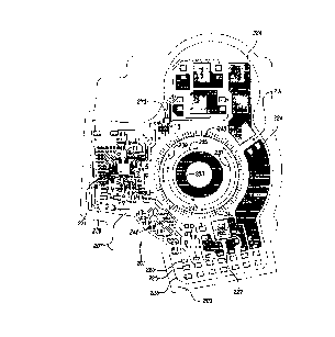
The construction of a first preferred embodiment central drive and power
transmission unit 43 is shown in Figure 2. An electromagnetic device such as
an
electric motor 51 is of a conventional fractional horsepower, do
electromagnetic
variety having a metallic motor housing within which are stationary permanent
magnets, a rotatable armature with wire windings, a rotatable armature shaft
joined
to the armature, a commutator electrically connected to the wire windings and
rotatable with the armature shaft, a brush card assembly and various
electronic
components, bushings and retainers. It will be apparent to those skilled in
the art that
other electric motor constructions can be readily substituted for that shown.
CA 02293218 1999-12-10
WO 98158825 PCT/US98I12543
_7_
A worm gear segment 53 is provided upon a portion of the armature shaft
. extending beyond the motor housing. A helical main gear 55 is enmeshed with
worm
gear segment 53 within a gear housing section of a gear enclosure.
Furthermore, a
drive pin 57 protrudes from a face of main gear 55 for selectively engaging
within
a channel 59 of one of three rotatable intermittent motion mechanisms or cams
71,
73 or 75. Cam 71 has a spur gear portion drivably enmeshed with a pinion gear
77
which, in turn, rotates a rear wiper shaft 79 coupled thereto by rivets,
insert molding,
a knurled press fit, et cetera. A liftgate door lock coupling assembly 135
couples
movement of cam 73 to that of Iiftgate lock 49 as can be observed in Figures 1
and
2. Similarly, rear window lock coupling assembly 141 mechanically couples
movement of cam 75 to that of window release lock 47. A second preferred
embodiment central drive and power transmission unit includes an intermittent
split
shaft clutch mechanism (not shown).
Figures 3 through 7 illustrate a printed circuit board 201 laminated onto an
aluminum gear cover 203 of the gear enclosure. Circuit board 201 includes a
first
circuit board layer 205, located closest to and parallel with cover 203, and a
second
parallel circuit board layer 207. Both layers 205 and 207 employ etched copper
foil
circuits on a high thermally conductive dielectric substrate. This metal cover
backed
circuit board assembly acts as a single piece, integrated heat sink, thereby
allowing
the large aluminum gear cover 203 to efficiently and directly dissipate heat
generated
by various transistors and other electronic components 209 mounted on second
circuit
board layer 207. Circuit board layers 205 and 207 are generally flexible until
adhered
onto cover 203. A ceramic filled, B-stage polymer is used between circuit
board
layers 205 and 207 to provide thermal conductivity. The metal mounted circuit
board assembly can be constructed in accordance with U.S. Patent No. 4,810,563
entitled "Thermally Conductive, Electrically Insulative Laminate, " which
issued on
March 7, 1989 to Decree et al, which is incorporated by reference herewithin.
Referring to Figure 3, circuit board layer 205 has a ground plane 221, various
trace patterns 223 and a set of terminal pads 225. Figure 4 shows multiple
positive
power pads 224, multiple ground pads 227, terminal pads 225 and a plurality of
conductive traces 229. Additionally, a conductive feedback pattern 231 is
disposed
on circuit board layer 207.
CA 02293218 1999-12-10
WO 98158825 PCTIUS98112543
n.
_g_
Feedback pattern 231 has an annular rounded shorting ring 233, also denoted
as POS 4, a first arcuate trace 235, also denoted as POS 1, a second arcuate
trace
237, also denoted as POS 2, third and fourth arcuate traces 239, 241, also
denoted
as POS 3, and an interval position ring 243, also denoted as POS 5. A set of
radially
extending conductive tics 245 are coupled together by a circular conductive
trace 247
for interval position ring 243. Tics 245 are equally spaced from each other
and are
disposed entirely around 360° . Arcuate traces 235 through 241 provide
course
absolute on/off signals indicative of whether main gear 55 (see Figure 2) is
within a
predetermined window wiping, door lock actuating, window lock release or dwell
positional ranges. However, tics 245 provide incremental signals indicative of
the
exact location of main gear 55, as well as the devices driven therefrom, such
as the
window wiper, door lock, window release device or intermittent motion
mechanisms,
within each positional range.
A main microprocessor 271 and a smaller transistor driving integrated circuit
273 are mounted upon circuit board layer 207 in a "flip chip" manner using
unpackaged silicon integrated circuits and conductive adhesive attachments, as
is
shown in Figure 7. A singuiated silicon integrated circuit is thermosonically
bonded
to create gold stud bumps. The stud bumps are then planarized with a press.
Next,
the studs are dipped into a conductive epoxy whereafter the silicon integrated
circuit
is aligned to the circuit pattern. The conductive epoxy is cured and a non-
conductive
under-fill material is then applied and cured. A "Panasert FCB-s" flip chip
bonder
from Panasonic can be used.
Referring to Figures 5 and 12, electronic components 209 are all mounted
upon the traces of circuit board 201. More specifically, four transistors U2
through
U5 are employed to drive electric motor 51 through leads M1. A diode D4 is
also
provided to protect U2 through US against reverse battery voltage. Another
transistor
U6 is employed to switch the heated back light function. Furthermore, a
varistor
VAR1, various capacitors referenced by prefix C, inductors referenced by the
prefix
L, and jumpers designated by prefix J, are also used. X1 designates the
crystal for
setting the proper frequency. These electronic components inwardly project
toward
the main gear to save space. However, it may be desirable to close JU1 and JU4
P2-
P4, and open JU2, JU3, and JU4 P1-P3 in a production type setting.
Furthermore,
CA 02293218 1999-12-10
WO 98/58825 PCT/US98112543
-9-
JU1 should be open, J2 should be closed, JU4 P2-P4 should be open and JU4 P1-
P3
should be closed, to operate the heated back light using the disclosed
software.
Moreover, to operate the Ul disable function given the disclosed software, JU3
. should be closed.
Referring now to Figures S, 6, 8 and 9, fourteen 90° terminals 301
are
mounted on terminal pads 225 of circuit board 201 for mating with a body wire
harness. Terminals 301 are preferably stamped from a phosphor-bronze metal
alloy
which can be obtained from Autosplice Co.; terminals 301 have a flat blade
configuration. Terminals 1 through 7 have double leg fastening to circuit
board 201
while terminals 8 through 14 have single leg fastening. First, blind holes are
drilled
in gear cover 203. Next, the holes are filled with non-conductive material to
prevent
the subsequently inserted terminals from shorting against gear cover 203.
Third,
circuit board 201 is laminated to gear cover 203, and then terminal holes are
drilled
in circuit board 201 and the filler material. Finally, the terminals are
mounted to
circuit board 201. However, surface mounting of the terminals to eliminate
drilling
and filling of the gear cover prior to laminating would be preferred.
A female electrical connector 331 has a peripherally slotted elastomeric seal
333 which fits within a squared notch 335 of gear housing 202. Distal ends of
terminals 301 project through rectangular slots 337 of female electrical
connector 331.
Thus, terminals 301 are accessible from a thin side of central drive and power
transmission unit 43 (see Figure 2) thereby serving to significantly reduce
the
packaging thickness.
The interface between main gear 55 and feedback pattern 231 of circuit hoard
201 may best be seen with reference to Figures 10 through 12. A stamped
beryllium
copper shorting bar 401 includes a base 403, heat staked onto polymeric gear
55, and
five bent fingers 405, 407, 409, 411 and 413 corresponding to POSS, POS3,
POS2,
POS1 and POS4, respectively. A silver coated contact ball 415 or stamped dome
on
each finger serves to ride against and conduct electricity through the
corresponding
conductive trace or tic 245.
Figure 12 further shows main microprocessor 271 as a Motorola
MC68HC705V8 microprocessor and transistor driving integrated circuit 273 as a
three phase Harris HIP4086 component using three high side and three low side
CA 02293218 1999-12-10
WO 98158825 PCT/US98112543
- 10-
drivers. Furthermore, Liftgate Lock ACT receives sensor inputs from the old
actuator
leads (since the liftgate motor or solenoid has been deleted with the present
invention). Additionally, a liftgate ajar, liftglass ajar, liftglass release
switch, liftgate
lock limit position and heated back light switches are all standard onloff
type switches
that are grounded. Moreover, electrical connector 301 is electrically
connected to a
main body controller or microprocessor in a multiplexed manner using an SAE J
1850
multiplex (MUX) protocol, an SAE J2178 multiplex message strategy, and an SAE
J2190 multiplex diagnostic standard within the rear node circuits; CAN or
other
MUX protocols can also be used. It is also important that the present
invention
employs semiconductors and an H-bridge MOSFET configuration rather than relays
in order to increase reliability, provide variable speed motor control and
reduce the
packaging size. The transistors are all 20 milliohm N-channel Harris MOSFETs.
A
courtesy lamp (not shown) can also be controlled by the rear node circuitry;
the rear
node, main microprocessor can be programmed to provide an automatic delay lamp
off feature after a predetermined time from closure of the rear liftgate or if
the lamp
is inadvertently left on for a predetermined period of time.
The operation and programmable software logic used to operate the preferred
embodiment control system of the present invention will now be described in
detail.
The rear node, main microprocessor of the preferred embodiment control system
of
the present invention is operated by a main software program, a portion of
which is
shown in the flow diagram of Figure 13. When power is applied through the
ignition
switch, the rear node, main microprocessor first tests and clears the random
access
memory (RAM), tests the read only memory (ROM), performs a check sum function,
initializes the J1850 hardware and clears the input and output ports while
setting up
the input and output direction. The main microprocessor then enables the timer
and
interrupts, enters a low power stop mode and then determines whether external
interrupts are detected. If external interrupts are detected, the main
microprocessor
initializes the system timer, enables the input task and enables the J1850
task. The
rear node, main microprocessor then determines if it needs to run the J1850
subroutine; if yes, the J1850 subroutine is run. If no, the main
microprocessor then
determines if it needs to run the electric motor subroutine; if yes, the
electric motor
subroutine is run. If no, the rear node, main microprocessor determines if it
needs
CA 02293218 1999-12-10
WO 98/58825 PCT/US98/12543
- 11 -
to run the lamps subroutine; if yes, the lamps subroutine is run. If no, the
rear node,
y main microprocessor then determines if it needs to run the heated back light
subroutine; if yes, the heated backlite subroutine is run. If no, the main
. microprocessor determines if it needs to run the inputs subroutine; if yes,
the main
microprocessor runs the inputs subroutine. If no, or upon completion of the
inputs
subroutine, the rear node, main microprocessor returns to determining the need
to run
the J 1850 subroutine.
Figure I4 shows the software loops for the new features resulting from the
incremental feedback pattern and code expressed within the Run Motor
Subroutine
of Figure 13. The incremental feedback code Run Motor Subroutine is first
initialized and then the selected Motion Profile of Figures 16 through 19 is
loaded.
Next, the appropriate electrical signal is given to the electric wiper motor
as part of
the Command Motor operation thereby causing the motor to drive the main gear,
intermittent motion mechanism and wiper shaft at the desired speed andlor
sweep
distance. A Detect Fault decision is made based upon detected deviations of
the
motion profile beyond acceptable limits. If yes, a Diagnostics Routine is
executed
to identify or rectify the fault. An unrectified fault condition sets the
Fault Flag. A
Fault Flag decision is subsequently made and if no Fault Flag is found, then
the loop
will return to the Load Motion profile operation. If a Fault Flag is found,
then the
subroutine will report the fault and issue a Stop Motor command.
Figure 15 discloses the Diagnostics Routine wherein the diagnostics step is
initialized, the Diagnostic Motion Profile is loaded and the Command Motor
step is
performed. Next, a Determine Fault Condition operation is commenced and a Log
Fault step is employed. Subsequently, a Continue to Operate decision is made:
if
yes, a Clear Fault Flag step is performed; if no, a Set Fault Flag operation
is
performed.
Figure 16 illustrates an exemplary soft start motion profile. The tics of the
feedback pattern on the circuit board generate electrical pulses which are
conducted
through the shorting bar and counted by the rear node, main microprocessor.
This
allows the microprocessor to determine the rate of angular travel or velocity
of the
main gear rotation, and corresponding wiper movement when the wiper
intermittent
motion mechanism is operabiy driven. Therefore, the microprocessor uses this
CA 02293218 1999-12-10
WO 98/58825 PCT/US98/12543
r
-12-
incremental feedback code to slowly ramp up the motor speed at the beginning
and
end of the wiper sweep travel in both the clockwise and counterclockwise
directions
while maintaining a generally flat, steady state speed through the middle
range of
movement in both the clockwise and counterclockwise sweep directions. This
speed
varying function prevents inadvertent gear teeth failure and wiper blade-to-
arm failure
when the inertia of the wiper mechanism would otherwise continue past the end
of
its travel even when the motor has reversed direction. This also serves to
prevent the
inertia of the wiper assembly and drive train from allowing the wiper blade to
forcibly contact against the painted vehicle body or exterior trim strips at
the end of
the wiper sweep.
Figure 17 discloses a normal, constant speed wiper profile employing
essentially instantaneous on/off ramp up and ramp down clockwise and
counterclockwise wiper speeds with abrupt interval dwell times between reverse
sweeps. The interval dwells, however, can be easily varied by merely using
software
and the incremental feedback code as a function of time.
Figure 18 shows a jogljam profile used to break ice on the window. A
quickly inclining and declining ramp up and ramp down energization of the
motor is
employed to quickly and locally oscillate the sweep of the wiper over the
sensed area.
The ice is sensed in a real time manner due to the slow down of the wiper in
this area
beyond that intended. After the localized oscillation function has been
completed, a
normal clockwise and counterclockwise steady state condition is employed.
The glass condition or fault deviation profiles are illustrated in Figure 19.
Line (a) is the desired start slope for the normal variable speed ramp up
condition.
The binding or stall condition is indicated by line (b) which is the degraded
start
slope. The solid line 501 indicates a wet glass condition, the faster speed
dashed line
503 indicates a dry glass condition while the lower speed dashed line 505 is
indicative
of a degraded system condition over time. Such a lifetime degradation can be
caused
by a lack of lubrication or failure of bearings within the motor. The profiles
of
Figure 19 are employed to sense the wiper performance on a real time,
automatic and
continuous basis. The automatic interval selection can be based upon the
change in
wipe time from dry conditions (t 3 - t ,) or wet conditions (t 2 - t ~). If t
dry = t 3 -
CA 02293218 1999-12-10
WO 98/58825 PCT/US98/12543
-13-
t ,, and t We~ = t z - t ,, then t Wel < t w,;Pe < t dn, (bounded t W,;Pe),
and t ;n~erval = f(t
W;P~) (where the interval is a function of t W;~~).
An alternate embodiment of the feedback pattern can be observed in Figure
20. A resistive feedback ring 551 has a circular shape broken at its ends.
Feedback
pattern 551 has an increased resistance from end 553 to opposite end 555. A
series
of outwardly radiating tics 557 are connected to feedback pattern 551. This
incremental resistive feedback loop 551 allows for use of an analog control
circuit
which provides for discrete step variable sensing, speed control and
programmable
distance control. The sensed resistance determined at a specific location is a
function
of the maximum resistance over the counted number of tics. Direct contact with
rhP
resistive material, instead of tics, would give infinitely variable
measurement.
Referring to Figure 21, another alternate embodiment feedback pattern 571 is
employed on a printed circuit board 573 for use with a fully digital encoder.
Three
or more concentric intermittent tic rings 575, 577 and 579 contain tics
slightly offset
from each other. An annular grounding ring 581 is also employed. This allows
for
very fine position sensing, speed sensing and control of the wiper without
need for
analog measurement.
While the preferred embodiment of this window wiper motor system has been
disclosed, it will be appreciated that various modifications may be made
without
departing from the present invention. For example, the feedback pattern may
have
differing configurations, shapes, and sizes. The incremental feedback pattern
and
software can also be employed in more conventional window wiper motors that do
not employ the preferred intermittent motion mechanisms. Alternately, a
ceramic
dipped, low carbon steel gear cover which contains a screened on conductor,
can be
employed in place of the disclosed laminated integral printed circuit board
and gear
cover assembly. The preferred electronic components and electrical circuits
may also
be varied in other analog and digital control arrangements as long as the
disclosed
functions are achieved. It is further envisioned that a hall effect sensor or
potentiometer could also be employed with the laminated circuit board and
cover
arrangement. While various materials have been disclosed, a variety of other
materials may also be used. It is intended by the following claims to cover
these and
CA 02293218 1999-12-10
WO 98/58825 PCT/US98112543
- 14-
other departures from the disclosed embodiments which fall within the true
spirit of
this invention.