Note: Descriptions are shown in the official language in which they were submitted.
CA 02293392 1999-12-06
"METHOD Fl7R HIGH-TEMPERATURE SHORT-TIME DISTILLATION OF RESIDUAL OILS"
Description
The invention relates to a process for high-temperature flash
distillation of liquid residue oil originating from processing
crude oil, natural bitumen or oil sand, wherein granular, hot
coke as a heat carrier (heat carrier coke) is mixed with the
residue oil in a mixer whereby 60 to 90 wt.% of the residue oil
is vaporized, in the mixer the non-volatile portion of the
residue oil containing the metal-laden asphaltenes is converted
in the mixture containing the heat carrier to oil vapour, gas
and coke, from the mixer the gases and vapours and the coke are
separately withdrawn, gases and vapours are cooled and a product
oil as a condensate and a gas are produced, the granular coke
withdrawn from the mixer is reheated and recirculated to the
mixer as heat carrier.
A similar process is known from the magazine "Erdol and
Kohle-Erdgas-Petrochemie/Hydrocarbon Technology" No. 42 (1989),
pages 235 to 237, where a special mixer with intermeshing,
uni-directionally rotating screws is presented which permits the
CA 02293392 1999-12-06
2
gases and vapours to be discharged and cooled after only a very
short retention time in the high-temperature zone of the mixer,
thus suppressing undesirable cracking processes in the gas
phase.
The objective of the present invention is to further develop the
known process and optimize the conditions for continuous process
operation. This results in maximizing the product oil yield and
to minimize the content of heavy metals (nickel, vanadium),
Conradson carbon (CCR) and heteroatoms (S, N) in the product
oil.
Using the above process, this objective is accomplished in that
the liquid residue oil is mixed in the mixer with hot heat
carrier coke having a temperature of 500 to 700°C at a weight
ratio of 1:3 to 1:30, at least 80 wt.o of the heat carrier coke
has a grain size range of 0.1 to 4 mm, at the beginning of the
mixing a liquid residue film is formed on the heat carrier coke
particles, the greater part of said film (e.g. 60 to 90 0)
being vaporized in the mixer at as low an operating temperature
as possible in the range of 450 to 600°C and preferably 500 to
560°C, the remaining liquid residue film on the coke is
subsequently converted to oil vapour, gas and coke at a
retention time of 6 to 60 seconds in the mixer, the coke
withdrawn from the mixer is dry, largely free from liquid
components and exhibits good flow properties and the gases and
vapours liberated are withdrawn from the mixer after a retention
time of 0.5 to 5 seconds.
Compared to the conventional vacuum distillation process, the
process of the invention raises the equivalent final boiling
CA 02293392 2004-07-22
3
point from about 560°C to about 700°C with a marked increase in
the distillation yield. At the same time, the non-distillable,
contaminant-laden (heavy metals, heteroatoms, CCR) asphaltenes
are converted to oil, gas and coke and the contaminants
preferably remain in the coke.
The lowest possible operation temperature in the mixer, when the
coke withdrawn from the mixer is just dry and has good flow
properties, results in the best yield and quality of the product
oil.
More particularly, the present invention provides a process for high
temperature
distilling of a liquid residue oil originating from processing crude oil,
natural
bitumen or oil sand, said liquid residue oil containing Konradson carbon,
heterocyclic sulfur and nitrogen-containing compounds, and asphaltenes laden
with heavy metal impurities wherein the heavy metal is selected from the group
consisting of nickel and vanadium, which comprises the steps of:
(a) mixing the liquid residue oil in a mixer with heat carrier coke particles
having a temperature of 500 to 700°C at a weight ratio of 1:3 to 1:30,
wherein at
least 80% of the heat carrier coke particles have a grain size in the range of
0.1
to 4 mm to form as a mixture a liquid residue oil film on the heat carrier
coke
particles;
(b) vaporizing 60 to 90% by weight of the liquid residue oil film at a
temperature of from 450°C. to 600°C to form an oil vapor/gas
mixture in the
mixer;
(c) converting the remaining part of the liquid residue oil film containing
the
asphaltenes laden with the heavy metal impurities into additional oil
vapor/gas
mixture and additional coke particles during a retention time of 6 to 60
seconds
in the mixer;
(d) discharging the coke particles formed during step (c) from the mixer, said
coke particles being dry, having good flow properties, and largely free from
liquid
components, reheating the coke particles discharged from the mixer and
CA 02293392 2004-07-22
3a
recirculating the reheated coke particles to the mixer according to step (a)
as
additional heat carrier coke particles;
(e) withdrawing from the mixer the oil vapor/gas mixture formed during steps
(b) and (c) after a retention time of 0.5 to 5 seconds, where not more than
25%
of the heavy metal impurities in the liquid residue oil are included in the
oil
vapor/gas mixture withdrawn; and
(f) condensing the oil vapor/gas mixture withdrawn during step (e) to obtain
separately a CS~. product oil condensate and a C4_ product gas.
Mixers suitable for the process include, for example, screw
mixers, rotary drum mixers, paddle mixers, plough or vibration
mixers. Moreover, mixers with intermeshing, uni-directionally
rotating screws, which are known and are described in German
Patent 12 52 623 and the corresponding US Patent 3 308 219 as
well as ir1 German Patent 22 13 861, can preferably be used. Due
to the interaction of the screws, the formation of deposits on
the screw surfaces and in the mixer housing is prevented.
Another embodiment of this process consists in passing the
liquid residue oil through a first mixing section for mixing
with the hot heat carrier coke and then through at least one
further mixing section and hot heat carrier coke and the residue
oil being fed to the mixer at the beginning of the first mixing
section and gases and vapours are liberated at temperatures in
the range of 450 to 600°C in the first mixing section and
further hot heat carrier coke being added to the mixture of heat
carrier coke and remaining residue oil from said first section
at the beginning of the second mixing section, the liberated
gases and vapours being discharged from the first and/or second
CA 02293392 1999-12-06
4
mixing section. This variant allows the adjustment of different
temperatures within a range of 450 to 600°C in the individual
mixing sections.
If at least two mixing sections are used for mixing the residue
oil with the hot heat carrier coke, the crucial first mixing
section can be operated at low temperatures which promotes the
capture of contaminants such as heavy metals (Ni, V),
heteroatoms (S, N) and Conradson carbon (CCR) in the coke which
is formed and, at the same time, suppresses undesirable cracking
processes in the gas phase. These cracking processes result in
increased C4_ gas formation and hence, reduce C5, product oil
yield and quality.
The second mixing section starts at the point where fresh heat
carrier coke is added from the outside to the coke mixture
coming from the first mixing section. Coke addition causes a
temperature increase in the second mixing section and
consequently temperature of the gases and vapours increases.
Normally, the heat carrier coke is added in such a rate as to
achieve a temperature increase of 5 to 50°C. This prevents
dew-point underruns in the piping between the mixer and the
condensing unit. At the same time, the higher temperatures
accelerate the coking of the remaining, non-volatile, liquid
residue components on the coke and hence, drying of the coke in
the mixer so that the latter loses its stickiness. This is a
prerequisite for ensuring good flowability of the coke in the
heat carrier circuit. Furthermore, it is also possible to
provide more than two mixing sections and add fresh coke at the
beginning of each section.
CA 02293392 1999-12-06
When using a mixing system with several mixing sections, about
50 to 95 0 of the total hot heat carrier coke feed for the mixer
is normally added to the first mixing section. The minimum hot
coke feed rate at the beginning of the second and each further
mixing section is 5 0 of the total hot heat carrier coke feed.
When using a mixer with only two mixing sections, the hot heat
carrier coke is generally added at a weight ratio of 20 :1 to
1:1 to the first and second mixing section.
Furthermore, it is possible to process in the second or a
subsequent mixing section a liquid residue oil differing from
that fed to the first mixing section. This allows, for example,
the residue oil fed to the second mixing section to be treated
at a higher temperature than the residue oil processed in the
first section. Such a second residue oil may also be thermally
treated in a second mixer connected partly in parallel with the
first mixer and operating at higher temperatures, for example.
Moreover, it may be beneficial to preheat the liquid residue oil
to temperatures of 100 to 450 °C before it is fed to the mixer.
Preheating reduces both the viscosity of the residue oil and the
heat requirement for vaporization, so that the non-volatile
proportion of the residue oil reaches the desired conversion
temperature faster.
Furthermore, an oxygen-free gas or steam may be added to the
mixer which offers the advantage of a reduced retention time of
the liberated gases and vapours in the mixer.
The process of the invention permits about 80 to 95 0 of the
heavy metals (Ni and V), about 50 to 70 0 of the Conradson
carbon (CCR) and 30 to 70 0 of the heteroatoms (S and N)
Y
CA 02293392 2004-07-22
6
contained in the residue oil to be captured in the coke which is
formed and a CS+ product oil with a yield of 70 to 85 wt.a is
recovered from the residue oil. After separation of the naphtha
and, where applicable, .the kerosene and gasoih fractions, this
product oil is suitable for catalytic processing.
Embodiments of the process are described ~~ith reference to the
-drawing. Each process variant presented uses mixers with
intermeshing, uni-directionally rotating screws.
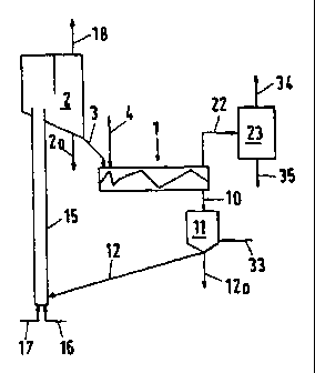
Fig. 1. shows a flow diagram of the process,
Fig. 2 shows a flow diagram of the process using a mixer
equipped with two mixing sections,
Fig. 3 shows a flow diagram of the process using two. mixers,
Fig 4 is' a diagrammatic representation showing a horizontal
section through the mixer taken along line IV-IV in Fig.
2.
Fig. 5 represents a horizontal section through a mixer with
outward tapering screws, analogous to the representation
in Fig. 4, and
Fig. 6 shows a vertical section through a mixer with
counter-rotating screws analogous to the representation
in Fig 1.
In the following description, similar features in the drawings have been given
similar reference numerals and, for a purpose of clarity, elements that are
described in reference to a figure, are not described afterwards.
As shown in Fig. 1, the mixer (1) is fed via feed line (3) with
hot heat carrier coke at 500 to 700 °C from collecting bin (2)
Concurrently, residue oil with a temperature of preferably 100
CA 02293392 2004-07-22
7
to 450°C is injected via line (4). The coke/residue oil weight
ratio is in the range of 3:1 to 30:1, which results in a mixing
temperature (conversion temperature) of 450 to 600 °C in the
mixer. At least 80 wt.% of the heat carrier coke are present in
the grain size range of 0.1 to 4 mm, the dsa value being in the
range of 0.2 to 2 mm to ensure maximum separation of the coke
from the liberated gases and oil vapours at the mixer outlet.
In the present case, the mixer (1) is equipped with two
intermeshing, uni-directionally rotating screws (8) and (9), as
diagramatically shown in Fig. 4. Alternatively, the mixer may be
equipped with three or more intermeshing, uni-directionally
rotating screws, which may also be arranged in an outward
tapering configuration (see Fig. 5). Each screw is designed as
screw conveyor and equipped with helical flights (8a) or (9a) as
shown in Figs. 4 and 5. The helical flights (8a) and (9a) have
different pitches along their lengths as shown in simplified
forth in Figs. 4 and 5. The flight pitch upstream of the
residue oiI feed point should preferably be shorter than the
flight pitch in the reaction zone to ensure that the coke enters
the reaction zone axially and is intimately mixed with the
residue oil in the reaction zone as result of the increasing
flight pitch.
As shown in Fig. 1, the hot, oil-free, granular coke discharges
at the end of the mixer (1) at a temperature of 450 to 600 °C
and drops through a duct (10) into a surge bin (1~) provided
with a stripping gas feed point at the bottom (33). Remaining
gases and vapours can flow out of the surge bin (11) via duct
(10) and discharge upwards. By means of line (12), coke is
withdrawn from the bin (11), part of the coke being discharged
from the system via line (12a) or line (2a). The remaining coke
passes through line (12) to the bottom of a pneumatic lift pipe
CA 02293392 1999-12-06
(15) which is supplied with combustion air via line (16) and, if
required, fuel via line (17). The coke is entrained with the
combustion gases to the top of the lift pipe (15) with part of
the coke or the fuel added being burnt in the process. The coke
heated up in the lift pipe (15) enters the collecting bin (2),
waste~gases being vented via line (18). The coke in collecting
bin (2) has a temperature in the range of 500 to 700 °C and
usually 550 to 650°C.
Gases and vapours exit the mixer (1) via duct (22) and enter
into a condensation unit (23), where they are rapidly cooled.
Product oil and gas are separately discharged via lines (35) and
(34) .
Fig 2. shows a mixer with two mixing sections (la) and (lb). At
the beginning of the first mixing section (la), hot coke from
collecting bin (2) is fed to the mixer via line (3). At the same
time, residue oil is fed via line (4) into the first mixing
section (la). At the beginning of the second mixing section
(lb), further hot coke is added via line (3a) and, if desired, a
second residue oil via line (4a). The gases and vapours
liberated in mixing sections (la) and (lb) are discharged from
the mixer via the common discharge line (22) or (22a) and routed
to the condensation unit (23).
Fig. 3 shows a process variant where two different residue oils
are fed to two separate mixers (1) and (5) via lines (4) and
(4a) where they are treated at different temperatures which are
their respective optimum conversion temperatures. The mixer (1)
shown in Fig. 6 is equipped with two pairs of counter-rotating
screws (25) and (26) which result in opposite transport
CA 02293392 1999-12-06
9
directions (27) and (28). Heat carrier coke is charged through
lines (3) and (3a) while residue oil is injected via lines (4)
and (4a). The coke is drawn off in the mixer centre through
duct (10), while gases and vapours are discharged via line (22).
Otherwise, the process is the same as that described together
with Fig. 1.
Example:
Using a process configuration as shown in Fig.l, 10 tons per
hour of a vacuum residue from crude oil distillation having a
temperature of 250 °C are injected into mixer (1) and mixed with
150 t/h of heat carrier coke having a temperature of 600°C. The
vacuum residue contains 20 wt.% CCR, 740 mg/kg vanadium and 120
mg/kg nickel. At the resulting operating temperature of 540°C
in the mixer, 8.2 t/h of oil vapour and gas and 1.8 t/h of fresh
coke are formed. The mixer is equipped with two intermeshing,
uni-directionally rotating screws. The oil vapour/gas mixture is
discharged from the mixer and routed to a condensation unit
where it is separated into 8.6 t/h product oil (C5.) containing
8.6 wt.% CCR, 83 mg/kg V and 11 mg/kg Ni, and also 1 t/h of gas
(C,.). The heat carrier coke discharging from the mixer together
with the fresh coke having formed on its surface is largely free
from liquid components and hence, dry and flowable.