Note: Descriptions are shown in the official language in which they were submitted.
CA 02293475 2006-05-30
WO 98/58279 PCT/EP98/03563
Description
Meteorological Electromagnetic Measuring System
TYJa- irivention relates to. an electxomagnetic measuririg system
for meteorology, with the aid of which spherics signals are
detected and analyzed.
Spherics signals are electromagnetic signals in the form of
irregular-ly shaped radiation pulses which occur in dynamic
processes in the atmosphere, for example in the approach
regions of thunderstorm or weather fronts, or in convective
cloud formations.
It is known from numerous observations that the individual
parameters of the spherics signals, such as nu.mber, ampli.tude
and frequency of the oscillations, and the pulse repetition
frequency, the frequency distribution over the frequency
values and the signal shapes are closely linked with the
weather processes causing them, in particular with the type
and.movement of atmospheric 3ir masses.
The previously known electroimagnetic measuring systems for
detecting and analyzing spherics signals are individual
receivers or sensors with the aid of which, depending on the
system, only a rough conclusion can be drawn concerning the
general, weather activity, since when receiving a sptrerics '
signal it is possible to assess at most the direction of the
source location, but not thE: signal strengtl-- at the source
location nor the variation produced by the different physical
states of the atmosphere along the propagation patti of this
spherics signal_
-1-
CA 02293475 2006-05-30
It is the object of the invention to specify an
electromagnetic measuring system for meteorology with the aid
of which the general weather activity can be more precisely
detected as a basis for a weather forecast.
According to an aspect of the present invention there is
provided an electromagnetic measuring system for
meteorology, comprising a plurality of measuring stations
disposed distributed spatially in a prescribed region of
space, each of the measuring stations having at least one
spherics receiver for receiving spherics signals and a
transmitter for transmitting measured data derived from the
spherics signals received in the measuring stations, a mean
spacing of respectively neighboring measuring stations
being less than 50 km to provide area-covering detection of
short-range spherics signals, and a central evaluation unit
associated with the measuring stations and receiving the
measured data.
The invention is based on the consideration that the
atmospheric events relevant for short-range forecasts
(nowcasts) generally lead to spherics signals of only a small
range. These spherics signals have a pulse duration of up to a
few 100 ms, and comprise one or more oscillations whose
oscillation frequency resides in the region between
approximately 3 and 100 kHz, that is to say in the VLF region.
The pulse repetition frequency of these spherics signals can
be up to a few 100 Hz. The maximum amplitude of the spherics
signals depends on the type and the distance of the signal
source, and is up to a few volts per meter for the electric
field vector. The typical discharge current strengths are less
than 1 kA, with the result that the effective range is at most
-2-
CA 02293475 1999-12-14
50 km. The spherics sources particularly relevant for the
short-range forecast can thus be measured only in the near
region, that is to say at distances which correspond to the
order of magnitude of the wavelength, with the result that
direction finding cannot be carried out for them, for physical
reasons. Spherics signals therefore differ clearly from
electromagnetic signals which are produced by lightning, since
the discharge currents in lightning are two orders of
magnitude higher and therefore have a greater range and, for
example, permit direction finding to be performed.
Consequently, the provision of an appropriately fine-meshed
measuring network according to the invention also renders it
possible to detect the spherics signals of small range in an
area-covering fashion and to use them for a reliable weather
forecast which is of high resolution in time and space.
The invention also proceeds from the consideration that it is
possible by means of a plurality of measuring stations which
are arranged distributed spatially in a prescribed region of
space in the form of a measuring station network to perform an
analysis of the variation experienced by a spherics signal in
the atmosphere along its propagation through the latter which
permits a better conclusion concerning the general weather
activity. In particular, in addition to the current weather
phenomena it is also possible to detect their causes, for
example air movements and discharging processes, by means of a
fine-meshed and continuously performed measurement of spherics
signals, with the result that a hit rate which is high, in
particular, for short-range forecasts (typically 15 minutes to
2 hours) is possible with regard to the future weather
development. The basic idea of the invention is thus to set up
an electromagnetic measuring system for meteorology whose
transmitters are represented by stochastically occurring
-3-
CA 02293475 1999-12-14
natural events within the atmosphere, and whose receivers are
formed by a network of measuring stations.
Furthermore, the invention is based on the consideration that
along their propagation path in the atmosphere, the spherics
signals are influenced by locally different thermodynamic and
electric conditions, and that it is possible in this way to
derive supplementary conclusions concerning the current
weather activity and the consequences arising therefrom for a
forecast.
The data provided by the measuring system according to the
invention therefore provide an area-covering image of the weak
atmospheric VLF emissions. These data can be used not only as
a basis for a reliable short-range weather forecast, but also,
in addition, as a reliable basis for the epidemiological
investigation of the biotropic effects of VLF pulses on human
organism.
The mean spacing of neighboring measuring stations, that is to
say the mesh width of the measuring network grid is preferably
between 10 km and 50 km, in particular approximately 30 km.
This permits an area-covering detection of the spherics
activities with a resolution of approximately 10 km.
In a preferred refinement of the invention, each measuring
station is provided with a processing unit for deriving
measured data from the received spherics signals. The
processing unit can in this case comprise simple filters
and/or analog signal processing stages with the aid of which
the signals are processed in analog fashion, with the result
that measured data are present in analog form.
-4-
CA 02293475 1999-12-14
In particular, the processing unit comprises a digital signal
processor upstream of which an analog-to-digital converter is
connected. In this case, the spherics signals can be subjected
to a digital signal analysis, for example an additional
digital filtering, in particular a spectral analysis or a
time-series analysis of successive spherics signals. The
measured data derived by the signal processor from such an
analysis are then transmitted as a digital data word to the
central evaluation unit.
The digital signal analysis is preferably undertaken with the
aid of suitable software, in particular software stored in an
EPROM and teleserviced by the central evaluation unit. In a
further advantageous refinement of the invention, an
appraising analysis of the spherics signals takes place in the
digital signal processor in which the spherics signals are
respectively assigned to an activity class with the aid of
prescribed appraising criteria. It is possible through the use
of such intelligent measuring stations substantially to reduce
the volume of measured data to be transmitted and to
facilitate their subsequent processing which can, for example,
comprise a rapid comparison of the pattern of the data image
of the weather activity currently transmitted from all
measuring stations to the central evaluation unit with already
stored data images of earlier weather activities, in order to
be able to derive forecasts from this comparison.
In particular, a separation of spherics signals from technical
noise signals is performed in the digital signal processor.
A signal conditioning stage with an analog filter is
preferably connected downstream of the spherics receiver,
which includes at least one magnetic VLF antenna. It is
possible by means of this measure for noise signals not based
-5-
CA 02293475 1999-12-14
on atmospheric causes, so-called technics signals, to be
eliminated, at least partially, even before a digital signal
analysis, since only electromagnetic signals in the frequency
bands relevant to spherics signals are fed for further
processing and analysis, with the result that the volume of
data to be analyzed digitally is reduced.
It is advantageous to provide in the central evaluation unit
means for determining the location of a spherics source by
evaluating the measured data of a plurality of neighboring
measuring stations, for example with the aid of cluster
algorithms. This permits a precise determination of location
even in the near-field region, since the errors which occur
unavoidably in the near-field region in the case of direction
finding and propagation time methods as are used, for example,
in lightning direction finding, are avoided.
In a particularly preferred refinement of the invention, a
central direction-finding transmitter is provided for
determining the alignment of at least a portion of the
spherics receiver.
In a preferred embodiment, the spherics receiver includes two
magnetic VLF antennas aligned horizontally and orthogonally
relative to one another. It is thereby possible for vertically
polarized spherics signals to be received from arbitrary
directions. Moreover, it is possible by comparing the signals
received in the mutually orthogonal horizontal magnetic
antennas to analyze the direction of propagation of vertically
polarized spherics signals of longer range or spherics signals
with a vertically polarized component, that is to say spherics
signals or spherics signal components whose electric field
vector is orientated perpendicular to, and whose magnetic
field vector is oriented in parallel to the earth's surface.
-6-
CA 02293475 1999-12-14
In a further preferred embodiment, the spherics receiver
comprises a vertically aligned magnetic VLF antenna, at least
in a portion of the measuring stations. It is thereby also
possible to detect spherics events which take place directly
over the relevant spherics receiver.
In a further advantageous embodiment, the spherics receiver
includes, in at least a portion of the measuring stations, a
dipole antenna for measuring a component, preferably the
vertical component, of the electric field. Further information
can be derived from the measurement of such a field component.
In particular, the relationships between the electric field
strength and the magnetic field strength, in particular their
mutual distance-dependent phase shift, can be analyzed.
In particular, in at least a portion of the measuring stations
a broadband VLF receiver with a broadcast antenna can be
provided for receiving longwave broadcast signals. It is
thereby possible also to use broadcast transmitters in
addition to the atmospheric transmitters for the purpose of
analyzing the state of the atmosphere. The broadcast signals
received by the measuring stations equipped with broadband
broadcast antennas can then be intercompared in the central
evaluation unit. It is then possible to draw conclusions from
the comparison concerning the atmospheric conditions along the
propagation path of the broadcast signal.
In a further advantageous embodiment, the measuring station
comprises at least one further pickup for detecting a further
local measurand. Such a local measurand can be, for example,
the pressure, the temperature, the conductivity, the humidity,
the insolation or the occurrence of precipitation.
-7-
CA 02293475 1999-12-14
In a preferred refinement, at least a portion of the measuring
stations comprises a measuring system for detecting their
current spatial position. This measuring system can be, for
example, a GPS measuring system. It is thereby also possible
to include measuring stations whose location is not exactly
fixed, for example measuring stations based at sea or
measuring stations in weather balloons.
In a preferred refinement of the invention, the transmitter is
controlled by events, that is to say transmission takes place
only when the measuring station records an event, that is to
say a spherics signal. Consequently, the number of the
measured data transmitted to the evaluation unit, and thus
also the computation outlay required in the processing unit,
can be reduced.
In particular, the transmitter can be activated in a time-
controlled fashion, thus rendering possible a temporally
continuous image of the atmospheric processes in the entire
region of space covered by the measuring stations.
In addition, a portion of the measuring stations can be
equipped with an VHF/UHF receiver in order to measure
atmospheric influences in the HF region.
In a particularly preferred refinement of the invention, at
least a portion of the measuring stations includes an array of
respectively similar spherics receivers which are arranged at
prescribed spacings from one another, in particular between 1
and 20 m. By means of these measures, short-range technical
noise signals can easily be separated from longer-range
genuine spherics signals by feeding for further processing
only those signals which occur coincidentally in all spherics
receivers.
-8-
CA 02293475 1999-12-14
Reference is made to the exemplary embodiment of the drawing
for the purpose of further explaining the invention. In the
drawing:
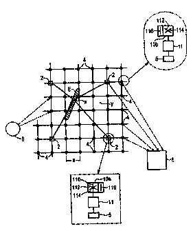
Figure 1 shows a diagrammatic basic representation of an
electromagnetic measuring system in accordance with the
invention with a multiplicity of measuring stations
distributed in a region of space, and
Figure 2 shows a preferred refinement of a measuring station
as used in the electromagnetic measuring system in accordance
with the invention.
In accordance with Figure 1, a multiplicity of measuring
stations 2, 4 are arranged in the fashion of a network in a
region of space. In the example of the figure, the measuring
stations 2, 4 form a square grid network. However, the
measuring stations 2, 4 need not be arranged in such a square
grid network. The mean spacing a of the measuring stations 2,
4 from one another, which corresponds to the mesh width of the
grid in the square grid represented, is less than 50 km,
preferably between 10 km and 50 km, in particular
approximately 30 km, thus ensuring that the short-range
spherics signals can be detected by at least a few neighboring
measuring stations 2, 4.
Each measuring station 2, 4 includes a transmitter 5 which
transmits to a central evaluation unit 6 the measured data
present in the measuring stations 2, 4 and derived from the
spherics signals as well as from further measurands possibly
recorded.
-9-
CA 02293475 1999-12-14
A fixed direction-finding transmitter 8, for example the DCF77
time-signal transmitter in Mainfingen, serves to monitor the
alignment of the receiving antennas located in the measuring
stations 2, 4.
The measuring station 2 represented by a square in the drawing
differs from the measuring stations 4 represented by a circle
to the effect that the first-mentioned measuring stations 2
have a spherics receiver l0a which comprises one vertical
antenna and two magnetic antennas arranged in a mutually
orthogonal and horizontal fashion 110 and 112, 114,
respectively, for example ferrite antennas or air-coil
antennas. By contrast, the measuring stations 4 have a
spherics receiver 10b which comprises only two horizontal
magnetic VLF antennas 112, 114, with the aid of which it is
not possible to measure a vertical magnetic field component.
The subnetwork formed from the measuring stations 2 is in this
case not so narrowly meshed as the subnetwork formed from the
measuring stations 4, since the vertical magnetic field
components additionally received by the spherics receiver 10a
belong, as a rule, only to spherics events which take place in
the atmosphere directly over the relevant measuring station 2
and are therefore already detected by the horizontal magnetic
VLF antennas 112, 114 of the neighboring measuring stations.
The spherics receivers 10a, lOb of a portion of the measuring
stations 2 and 4, respectively, can be equipped, in addition,
with a vertical dipole antenna 116 in order also to measure
the vertical component of the electric field in addition to
the horizontal components of the magnetic field.
Each measuring station 2, 4 is equipped with a processing unit
11 in which the received spherics signals are processed into
analog or digital data which are then transmitted to the
-10-
CA 02293475 1999-12-14
central evaluation unit 6 via the transmitter 5, for example a
telephone modem or a radio transmitter. Such a processing unit
11 can consist in a simple case merely of an analog arithmetic
unit, for example a filter.
Instead of a single spherics receiver 10a or lOb, at least a
portion of the measuring stations 2, 4 includes in each case a
linear or matrix-shaped array of similar spherics receivers
l0a or lOb, which are arranged at spacings of approximately 1
to 20 m from one another. It is possible by means of this
measure for technically generated VLF pulses with ranges of a
few meters to be separated in a simple way from genuine
spherics signals with ranges of several kilometers.
In an alternative refinement, the processing unit 11 can
subject the spherics signals themselves, which have been
digitized in a digital signal processor, to further digital
signal processing before transmitting them to the central
evaluation unit 6.
Illustrated in the figure - in a fashion emphasized by
hatching - is an atmospheric event E, for example a developing
cold front. In such a cold front, characteristic discharge
processes take place which are the cause of spherics signals
characteristic of this process. Experience has shown that the
presence of such a cold front leads chiefly to relatively
longwave vertically polarized spherics signals. Consequently,
it is possible with the aid of the measuring stations 2, 4 to
determine the location x of the event triggering a vertically
polarized spherics signal, the reception of the spherics
signal in two measuring stations 2, 4 even being sufficient in
principle. The spherics signals received by the measuring
stations 2, 4 and analyzed with regard to their place of
origin and manifestation now permit the statement that there
-11-
CA 02293475 1999-12-14
is a cold front at the location x. The measuring stations 2
located in the vicinity of the event E, in the example the
cold front, additionally receive with their vertical VLF
antennas 110, in particular, weak horizontally polarized
spherics signals whose signal variation, signal frequency and
signal duration permit a conclusion as to whether the cold
front is developing or advancing. It is therefore possible by
means of the distribution of a multiplicity of measuring
stations 2, 4 over an area to obtain comprehensive information
on the weather activity which can serve as a basis for a
reliable short-range weather forecast. Thus, in the case of
the use of such a device according to the invention precise
forecasts can be made to the effect that the development of a
cold front at a location y can be forecast precisely for a
period of from half an hour up to several hours.
However, determining the location of the spherics signals by
direction finding is possible only for longer-range spherics
signals. The determination of the location of the source of
short-range spherics signals is therefore performed in the
central evaluation unit 6 by using so-called cluster
algorithms to evaluate the data on pulse rate and power
density received from mutually neighboring measuring stations
2, 4.
In accordance with Figure 2, the measuring station 2 includes
at least one spherics receiver l0a equipped with three
magnetic VLF antennas 110, 112, 114 and an additional
broadband VLF receiver 12 with a horizontal broadcast antenna
120. It can also be seen in the figure that the spherics
receiver l0a is additionally equipped with a dipole antenna
116.
-12-
CA 02293475 1999-12-14
Assigned to the spherics receiver 10a is a signal conditioning
stage 14 which includes, for example, analog filters for the
purpose of separating the spherics signals from technical
noise signals (technics signals). In an alternative
advantageous refinement, a plurality of spherics receivers 10a
are arranged in the form of an array in the measuring station
2, as is indicated by points. It is possible by means of this
measure to separate spherics signals from technical noise
signals in a particularly simple and reliable fashion.
Connected downstream of the VLF receiver 12 is a controllable
filter 16 with the aid of which said receiver can be tuned to
the respective transmitter. Moreover, the broadcast antenna of
the VLF receiver 12 can be remotely controlled via the signal
processor 22 by the central evaluation unit G.
Also provided in the measuring station are a number of further
pickups 18 with the aid of which further local measurands, for
example temperature, air pressure, relative humidity, electric
conductivity of the atmosphere are detected.
A signal conditioning stage 14, a controllable filter 16 and a
pickup 18 are connected with their output to a multiplexer 20
whose address input is driven by a signal processor 22, with
the result that in each case only the signal associated with
the current address input is present at the output of the
multiplexer 20. The measuring signal present at the output of
the multiplexer 20 is fed to the signal processor 22 via an
analog-to-digital converter 24.
The spherics receiver l0a is, moreover, assigned a transmitter
26 which, under the control of the signal processor 22, emits
prescribed transmitted signals for self-testing the spherics
receiver 10a.
-13-
CA 02293475 1999-12-14
The measured data present, in particular the spherics signals,
are analyzed in the signal processor 22. This analysis can
consist in using plausibility checks to separate "fake"
spherics signals from "genuine" spherics signals. Given the
presence of a plurality of spherics receivers in the measuring
station, this can be done, for example, by further processing
only signals simultaneously received by all spherics
receivers.
Furthermore, it is also possible to generate in the digital
signal processor 22 an interpreted signal derived from the
spherics signals which can be transmitted, via a transmitter
5, to the central evaluation unit 6, for example as a data
word with an information content obtained by interpretation of
the spherics signals, for example with the information content
of "cold front at location x" or "cold front developing at the
location of the measuring station".
The algorithms for digital signal processing are stored in the
signal processor 20 in an EPROM, and can be updated freely via
a modem present in the transmitter S. In the case of measuring
stations with only one spherics receiver, for example, these
algorithms comprise an algorithm for digitally separating the
spherics signals from technical noise signals (discriminator)
which could not be filtered out by the analog filter of the
signal conditioning stage 14.
Also stored in the digital signal processor 22 is an algorithm
for analyzing the spherics signals (analyzer). This analysis
can be performed by virtue of the fact that received signals
identified as spherics signals are analyzed in defined
spectral intervals, for example in the intervals 1 to 10 kHz,
to 20 kHz, 20 to 30 kHz, 30 to 50 kHz, 50 to 100 kHz, 100
-14-
CA 02293475 1999-12-14
to 200 kHz, 200 to 500 kHz, for example in fixed temporal
measuring intervals, for example in a measuring interval of
one minute duration. For this purpose, the spectral power
densities in these spectral regions are integrated over the
corresponding time interval, and the number of pulses in this
time interval are determined. A fixed number of such measuring
intervals (for example 15) is combined to form one
transmission interval each, upon the expiry of which the data
collected in the process are transmitted to the central
evaluation unit 6 for further processing and archiving.
Moreover, the received spherics signals can be processed and
analyzed to such an extent in the signal processor 22 that
they can be assigned to an activity class in a prescribed
classification scheme, and only a transmission of the activity
class need be undertaken upon expiry of a transmission
interval. In this case, an activity class is to be understood
as the combination of the measured values of a measuring
interval in accordance with a pattern recognized as typical.
The volume of the data to be transmitted is substantially
reduced by this measure.
Also provided in the exemplary embodiment is an UHF/VHF
receiver 28 with the aid of which the transmitted television
signals of normal television transmitters can be received in
the HF region. This permits a supplementary analysis and
interpretation of the weather activity with the aid of
electromagnetic signals in the HF region.
Moreover, in the case of the measuring station explained in
more detail in the exemplary embodiment, provision is made of
a measuring system 30 for detecting the current spatial
position, for example a GPS receiving system, with the aid of
-15-
CA 02293475 1999-12-14
which the current location of the measuring station can be
determined. This is advantageous, for example, in the case of
non-stationary measuring stations.
-16-