Note: Descriptions are shown in the official language in which they were submitted.
CA 02293590 1999-12-02
WO 99/01706 PCTIUS98/13233
-1-
PROCESS FOR LIQUEFYING A NATURAL GAS STREAM
CONTAINING AT LEAST ONE FREEZABLE COMPONENT
FIELD OF THE INVENTION
This invention relates to a natural gas liquefaction process, and more
particularly relates to a process to produce pressurized liquid natural gas
(PLNG)
from a natural gas stream containing at least one freezable component.
BACKGROUND OF THE INVENTION
Because of its clean burning qualities and convenience, natural gas has
become widely used in recent years. Many sources of natural gas are located in
remote areas, great distances from any commercial markets for the gas.
Sometimes a
pipeline is available for transporting produced natural gas to a commercial
market.
When pipeline transportation is not feasible, produced natural gas is often
processed
into liquefied natural gas (which is called "LNG") for transport to market.
One of the distinguishing features of a LNG plant is the large capital
investment required for the plant. The equipment used to liquefy natural gas
is
generally quite expensive. The liquefaction plant is made up of several basic
systems,
including gas treatment to remove impurities, liquefaction, refrigeration,
power
facilities, and storage and ship loading facilities. While the cost of LNG
plant can
vary widely depending upon plant location, a typical conventional LNG project
can
cost from U.S. $5 billion to U.S. $10 billion, including field development
costs. The
plant's refrigeration systems can account for up to 30 percent of the cost.
LNG refrigeration systems are expensive because so much refrigeration is
needed to liquefy natural gas. A typical natural gas stream enters a LNG plant
at
pressures from about 4,830 kPa (700 psia) to about 7,600 kPa (1,100 psia) and
temperatures from about 20 C to about 40 C. Natural gas, which is
predominantly
methane, cannot be liquefied by simply increasing the pressure, as is the case
with
heavier hydrocarbons used for energy purposes. The critical temperature of
methane
is -82.5 C. This means that methane can only be liquefied below that
temperature
CA 02293590 1999-12-02
WO 99/01706 PCTIUS98/13233
-2-
regardless of the pressure applied. Since natural gas is a mixture of gases,
it liquefies
over a range of temperatures. The critical temperature of natural gas is
between about
-85 C and -62 C. Typically, natural gas compositions at atmospheric pressure
will
liquefy in the temperature range between about -165 C and -155 C. Since
refrigeration equipment represents such a significant part of the LNG facility
cost,
considerable effort has been made to reduce refrigeration costs.
Many systems exist in the prior art for the liquefaction of natural gas by
sequentially passing the gas at an elevated pressure through a plurality of
cooling
stages whereupon the gas is cooled to successively lower temperatures until
the gas
liquefies. Conventional liquefaction cools the gas to a temperature of about -
160 C at
or near atmospheric pressure. Cooling is generally accomplished by heat
exchange
with one or more refrigerants such as propane, propylene, ethane, ethylene,
and
methane. Although many refrigeration cycles have been used to liquefy natural
gas,
the three types most commonly used in LNG plants today are: (1) "cascade
cycle"
which uses multiple single component refrigerants in heat exchangers arranged
progressively to reduce the temperature of the gas to a liquefaction
temperature,
(2) "expander cycle" which expands gas from a high pressure to a low pressure
with a
corresponding reduction in temperature, and (3) "multi-component refrigeration
cycle" which uses a multi-component refrigerant in specially designed
exchangers.
Most natural gas liquefaction cycles use variations or combinations of these
three
basic types.
In conventional LNG plants water, carbon dioxide, sulfur-containing
compounds, such as hydrogen sulfide and other acid gases, n-pentane and
heavier
hydrocarbons, including benzene, must be substantially removed from the
natural gas
processing, down to parts-per-million (ppm) levels. Some of these compounds
will
freeze, causing plugging problems in the process equipment. Other compounds,
such
as those containing sulfur, are typically removed to meet sales
specifications. In a
conventional LNG plant, gas treating equipment is required to remove the
carbon
dioxide and acid gases. The gas treating equipment typically uses a chemical
and/or
physical solvent regenerative process and requires a significant capital
investment.
Also, the operating expenses are high. Dry bed dehydrators, such as molecular
sieves,
. T_. _ . . .. . ._.__.__._.._._.._.~__...._...._. . . ......T_. ._......._.,
_..._......_... ,.. ... .
CA 02293590 1999-12-02
WO 99/01706 PCTIUS98/13233
-3-
are required to remove the water vapor. A scrub column and fractionation
equipment
are used to remove the hydrocarbons that tend to cause plugging problems.
Mercury
is also removed in a conventional LNG plant since it can cause failures in
equipment
constructed of aluminum. In addition, a large portion of the nitrogen that may
be
present in natural gas is removed after processing since nitrogen will not
remain in the
liquid phase during transport of conventional LNG and having nitrogen vapors
in
LNG containers at the point of delivery is undesirable.
There is a continuing need in the industry for an improved process for
liquefying natural gas that contains CO2 in concentrations that would freeze
during
the liquefaction process and at the same time having power requirements that
are
economic.
SUMM.ARY
The invention relates generally to a process for producing pressurized
liquefied natural gas (PLNG) in which the natural gas feed stream contains a
freezable
component. The freezable component, although typically C02, H2S or another
acid
gas, can be any component that has the potential for forming solids in the
separation
system.
In the process of this invention, a multi-component feed stream containing
methane and a freezable component having a relative volatility less than that
of
methane is introduced into a separation system having a freezing section
operating at
a pressure above about 1,380 kPa (200 psia) and under solids forming
conditions for
the freezable component and a distillation section positioned below the
freezing
section. The separation system, which contains a controlled freezing zone
("CFZ"),
produces a vapor stream rich in methane and a liquid stream rich in the
freezable
component. At least a portion of the vapor stream is cooled to produce a
liquefied
stream rich in methane having a temperature above about -112 C (-170 F) and a
pressure sufficient for the liquid product to be at or below its bubble point.
A first
portion of the liquefied stream is withdrawn from the process as a pressurized
liquefied product stream (PLNG). A second portion of the liquefied stream is
= CA 02293590 1999-12-02 ~
WO 99/01706 PCT/US98/13233
-4-
returned to the separation system to provide refrigeration duty to the
separation
system.
In one embodiment, a vapor stream is withdrawn from an upper region of the
separation system and is compressed to a higher pressure and cooled. The
cooled,
compressed stream is then expanded by an expansion means to produce a
predominantly liquid stream. A first portion of the liquid stream is fed as a
reflux
stream to the separation system, thereby providing open-loop refrigeration to
the
separation system, and a second portion of the liquid stream is withdrawn as a
product
stream having a temperature above about -112 C (-170 F) and a pressure
sufficient
for the liquid product to be at or below its bubble point.
In another embodiment, a vapor stream is withdrawn from an upper region of
the separation system and cooled by a closed-loop refrigeration system to
liquefy the
methane-rich vapor stream to produce a liquid having a temperature above about
-112 C (-170 F) and a pressure sufficient for the liquid product to be at or
below its
bubble point.
The method of the present invention can be used both for the initial
liquefaction of a natural gas at the source of supply for storage or
transportation, and
to re-liquefy natural gas vapors given off during storage and ship loading.
Accordingly, an object of this invention is to provide an improved, integrated
liquefaction and CO2 removal system for the liquefaction or reliquefaction of
natural
gas with high CO2 concentrations (greater than about 5%). Another object of
this
invention is to provide an improved liquefaction system wherein substantially
less
compression power is required than in prior art systems. A still further
object of the
invention is to provide a more efficient liquefaction process by keeping the
process
temperature for the entire process above about -112 C, thereby enabling the
process
equipment to be made of less expensive materials than would be required in a
conventional LNG process that have at least part of the process operating at
temperatures down to about -160 C. The very low temperature refrigeration of
conventional LNG process is very expensive compared to the relatively mild
refrigeration needed in the production of PLNG in accordance with the practice
of this
invention.
T _ _......_.~.._ ...,.....__ . _ _..
CA 02293590 1999-12-02
WO 99/01706 PCT/US98/13233
-5-
BRIEF DESCRIPTION OF THE DRAWINGS
The present invention and its advantages will be better understood by
referring
to the following detailed description and the attached Figures which are
schematic
flow diagrams of representative embodiments of this invention.
Figure 1 is a schematic representation of a cryogenic, CFZ process generally
illustrating a closed-loop refrigeration cycle for producing pressurized
liquefied
natural gas in accordance with the process of this invention.
Figure 2 is a schematic representation of a cryogenic, CFZ process generally
illustrating an open-loop refrigeration cycle for producing pressurized
liquefied
natural gas in accordance with the process of this invention.
Figure 3 is a schematic representation of still another embodiment of the
present invention in which carbon dioxide and methane are distillatively
separated in
a distillation column having a CFZ in which one overhead product stream is
pressurized liquefied natural gas and another overhead product stream is
product sales
gas.
The flow diagrams illustrated in the Figures present various embodiments of
practicing the process of this invention. The Figures are not intended to
exclude from
the scope of the invention other embodiments that are the result of normal and
expected modifications of these specific embodiments. Various required
subsystems
such as pumps, valves, flow stream mixers, control systems, and sensors have
been
deleted from the Figures for the purposes of simplicity and clarity of
presentation.
DESCRIPTION OF THE PREFERRED EMBODIMENTS
The process of this invention distillatively separates in a separation system
a
multi-component feed stream containing methane and at least one freezable
component having a relative volatility less than that of methane, wherein the
separation system contains a controlled freezing zone ("CFZ"). The separation
system produces an overhead vapor stream enriched with methane and a bottoms
product enriched with the freezable component. At least part of the overhead
vapor
stream is then liquefied to produce liquefied natural gas product having a
temperature
= CA 02293590 1999-12-02 =
WO 99/01706 PCTIUS98/13233
-6-
above about -112 C (-170 F) and a pressure sufficient for the liquid product
to be at
or below its bubble point. This product is sometimes referred to herein as
pressurized
liquid natural gas ("PLNG"). Another portion of such liquefied overhead stream
is
returned to the separation system as a reflux stream.
The term "bubble point" is the temperature and pressure at which a liquid
begins to convert to gas. For example, if a certain volume of PLNG is held at
constant pressure, but its temperature is increased, the temperature at which
bubbles
of gas begin to form in the PLNG is the bubble point. Similarly, if a certain
volume
of PLNG is held at constant temperature but the pressure is reduced, the
pressure at
which gas begins to form defines the bubble point. At the bubble point, PLNG
is
saturated liquid. It is preferred that the PLNG is not just condensed to its
bubble
point, but further cooled to subcool the liquid. Subcooling the PLNG reduces
the
amount of boil-off vapors during its storage, transportation and handling.
Prior to this invention, it was well understood by those skilled in the art
that
CFZ could remove unwanted CO2. It was not appreciated that the CFZ process
could
be integrated with a liquefaction process to produce PLNG.
The process of the present invention is more economic to use since the process
requires less power for liquefying the natural gas than processes used in the
past and
the equipment used in the process of this invention can be made of less
expensive
materials. By contrast, prior art processes that produce LNG at atmospheric
pressures
having temperatures as low as -160 C require process equipment made of
expensive
materials for safe operation.
In the practice of this invention, the energy needed for liquefying natural
gas
containing significant concentrations of a freezable component such as CO2 is
greatly
reduced over energy requirements of a conventional process for producing LNG
from
such natural gas. The reduction in necessary refrigeration energy required for
the
process of the present invention results in a large reduction in capital
costs,
proportionately lower operating expenses, and increased efficiency and
reliability,
thus greatly enhancing the economics of producing liquefied natural gas.
At the operating pressures and temperatures of the present invention, about
3'/2
weight percent nickel can be used in piping and facilities in the coldest
operating
. _~..._. .r
CA 02293590 1999-12-02
WO 99/01706 PCT/US98/13233
-7-
areas of the liquefaction process, whereas the more expensive 9 weight percent
nickel
or aluminum is generally required for the same equipment in a conventional LNG
process. This provides another significant cost reduction for the process of
this
invention compared to prior art LNG processes.
The first consideration in cryogenic processing of natural gas is
contamination. The raw natural gas feed stock suitable for the process of this
invention may comprise natural gas obtained from a crude oil well (associated
gas) or
from a gas well (non-associated gas). The raw natural gas often contains
water,
carbon dioxide, hydrogen sulfide, nitrogen, butane, hydrocarbons of six or
more
carbon atoms, dirt, iron sulfide, wax, and crude oil. The solubilities of
these
contaminants vary with temperature, pressure, and composition. At cryogenic
temperatures, C02, water, and other contaminants can form solids, which can
plug
flow passages in cryogenic heat exchangers. These potential difficulties can
be
avoided by removing such contaminants if conditions within their pure
component,
solid phase temperature-pressure phase boundaries are anticipated. In the
following
description of the invention, it is assumed that the natural gas stream
contains CO2. If
the natural gas stream contains heavy hydrocarbons which could freeze out
during
liquefaction, these heavy hydrocarbons will be removed with the CO2.
One advantage of the present invention is that the warmer operating
temperatures enables the natural gas to have higher concentration levels of
freezable
components than would be possible in a conventional LNG process. For example,
in
a conventional LNG plant that produces LNG at -160 C, the CO2 must be below
about 50 ppm to avoid freezing problems. In contrast, by keeping the process
temperatures above about -112 C, the natural gas can contain CO2 at levels as
high as
about 1.4 mole % CO2 at temperatures of -112 C and about 4.2% at -95 C without
causing freezing problems in the liquefaction process of this invention.
Additionally, moderate amounts of nitrogen in the natural gas need not be
removed in the process of this invention because nitrogen will remain in the
liquid
phase with the liquefied hydrocarbons at the operating pressures and
temperatures of
the present invention. The ability to reduce, or in some cases omit, the
equipment
required for gas treating and nitrogen rejection provides significant
technical and
= CA 02293590 1999-12-02
WO 99/01706 PCT/US98/13233
-8-
economic advantages. These and other advantages of the invention will be
better
understood by referring to the liquefaction process illustrated in the
Figures.
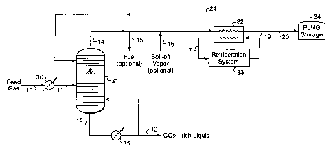
Referring to Fig. 1, a natural gas feed stream 10 enters the system at a
pressure
above about 3,100 kPa (450 psia) and more preferably above about 4,800 kPa
(700 psia) and temperatures preferably between about 0 C and 40 C; however,
different pressures and temperatures can be used, if desired, and the system
can be
modified accordingly. If the gas stream 10 is below about 1,380 kPa (200
psia), it can
be pressurized by a suitable compression means (not shown), which may comprise
one or more compressors. In this description of the process of this invention,
it is
assumed that the natural gas stream 10 has been suitably treated to remove
water
using conventional and well known processes (not shown in Fig. 1) to produce a
"dry" natural gas stream.
Feed stream 10 is passed through cooler 30. The cooler 30 may comprise one
or more conventional heat exchangers that cool the natural gas stream to
cryogenic
temperatures, preferably down to about -50 C to -70 C and more preferably to
temperatures just above the solidification temperature of CO2. The cooler 30
may
comprise one or more heat exchange systems cooled by conventional
refrigeration
systems, one or more expansion means such as Joule-Thomson valves or
turboexpanders, one or more heat exchangers which use liquid from the lower
section
of the fractionation column 31 as coolant, one or more heat exchangers that
use the
bottoms product stream of column 31 as coolant, or any other suitable source
of
cooling. The preferred cooling system will depend on the availability of
refrigeration
cooling, space limitation, if any, and environmental and safety
considerations. Those
skilled in the art can select a suitable cooling system taking into account
the operating
circumstance of the liquefaction process.
The cooled stream 11 exiting the feed cooler 30 is conveyed into a
fractionation column 31 having a controlled freeze zone ("CFZ"), which is a
special
section to handle solidification and melting of CO2. The CFZ section, which
handles
solidification and melting of C02, does not contain packing or trays like
conventional
distillation columns, instead it contains one or more spray nozzles and a
melting tray.
Solid CO2 forms in the vapor space in the distillation column and falls into
the liquid
CA 02293590 1999-12-02
WO 99/01706 PCTIUS98/13233
-9-
on the melting tray. Substantially all of the solids that form are confined to
the CFZ
section. The distillation column 31 has a conventional distillation section
below the
CFZ section and preferably another distillation section above the CFZ section.
Design and operation of a fractionation column 31 are known to those skilled
in the
art. Examples of CFZ designs are illustrated in U.S. patent numbers 4,533,372;
4,923,493; 5,062,270; 5,120,338; and 5,265,428.
A C02-rich stream 12 exits the bottom of column 31. The liquid bottom
product is heated in a reboiler 35 and a portion is returned to the lower
section of
column 31 as reboiled vapor. The remaining portion (stream 13) leaves the
process as
C02-rich product. A methane-rich stream 14 exits the top of column 31 and
passes
through a heat exchanger 32 which is cooled by stream 17 that is connected to
a
conventional closed-loop refrigeration system 33. A single, multi-component,
or
cascade refrigeration system may be used. A cascade refrigeration system would
comprise at least two closed-loop refrigeration cycles. The closed-loop
refrigeration
system may use as refrigerants methane, ethane, propane, butane, pentane,
carbon
dioxide, hydrogen sulfide, and nitrogen. Preferably, the closed-loop
refrigeration
system uses propane as the predominant refrigerant. Although Fig. 1 shows only
one
heat exchanger 32, in the practice of this invention multiple heat exchangers
may be
used to cool the vapor stream 14 in multiple stages. Heat exchanger 32
preferably
condenses substantially all of vapor stream 14 to a liquid. Stream 19 exiting
the heat
exchanger has a temperature above about -112 C and a pressure sufficient for
the
liquid product to be at or below its bubble point. A first portion of the
liquid stream
19 is passed as stream 20 to a suitable storage means 34 such as a stationary
storage
tank or a carrier such as a PLNG ship, truck, or railcar for containing the
PLNG at a
temperature above about -112 C and a pressure sufficient for the liquid
product to be
at or below its bubble point. A second portion of the liquid stream 19 is
returned as
stream 21 to the separation column 31 to provide refrigeration to the
separation
column 31. The relative proportions of streams 20 and 21 will depend on the
composition of the feed gas 10, operating conditions of the separation column
31, and
desired product specifications.
~ CA 02293590 1999-12-02 =
WO 99/01706 PCT/US98/13233
-10-
In the storage, transportation, and handling of liquefied natural gas, there
can
be a considerable amount of "boil-off," the vapors resulting from evaporation
of
liquefied natural gas. The process of this invention can optionally re-liquefy
boil-off
vapor that is rich in methane. Referring to Fig. 1, boil-off vapor stream 16
may
optionally be introduced to vapor stream 14 prior to cooling by heat exchanger
32.
The boil-off vapor stream 16 should be at or near the pressure of the vapor
stream 14
to which the boil-off vapor is introduced. Depending on the pressure of the
boil-off
vapor, the boil-off vapor may need to be pressure adjusted by one or more
compressors or expanders (not shown in the Figures) to match the pressure at
the
point the boil-off vapor enters the liquefaction process.
A minor portion of the vapor stream 14 may optionally be removed from the
process as fuel (stream 15) to supply a portion of the power needed to drive
compressors and pumps in the liquefaction process. This fuel may optionally be
used
as a refrigeration source to assist in cooling the feed stream 10.
Fig. 2 illustrates in schematic form another embodiment of this invention in
which open-loop refrigeration is used to provide refrigeration to the
separation
column 51 and to produce PLNG. Referring to Fig. 2, a multi-component gas
stream
50 containing methane and carbon dioxide that has been dehydrated and cooled
by
any suitable source of cooling (not shown in Fig. 2) is fed into a CFZ column
51
which has essentially the same design as separation column 31 of Fig 1. This
embodiment effectively manages the potential for the formation of solids in
the
liquefaction process by feeding stream 64 directly into CFZ column 51.
The temperature of the gas fed into CFZ column 51 is preferably above the
CO2 solidification temperature. A methane-enriched vapor stream 52 exits the
overhead of CFZ column 51 and a carbon dioxide-enriched stream 53 exits the
bottom
of CFZ column 51. The liquid bottom product is heated in a reboiler 65 and a
portion
is returned to the lower section of the CFZ column 51 as reboiled vapor. The
remaining portion (stream 54) leaves the process as C02-rich liquid product.
A first portion of the overhead stream 52 is refluxed back to the CFZ column
51 as stream 64 to provide open-loop refrigeration to the CFZ column 51. A
second
portion of the overhead stream 52 is withdrawn (stream 63) as a PLNG product
CA 02293590 1999-12-02
WO 99/01706 PCT/US98/13233
-11-
stream at a pressure that is at or near the operating pressure of the CFZ
column 51 and
at a temperature above about -112 C (-170 F). A third portion of the overhead
stream 52 may optionally be withdrawn (stream 59) for use as sales gas or
further
processed.
The principal components of open-loop refrigeration in this embodiment
comprise compressing by one or more compressors 57 the overhead stream 52
exiting
the top of the CFZ column 51, cooling the compressed gas by one or more
coolers 58,
passing at least part of the cooled gas (stream 61) to one or more expansion
means 62
to decrease the pressure of the gas stream and to cool it, and feeding a
portion (stream
64) of the cooled, expanded stream to the CFZ column 51. Refluxing part of the
overhead stream 52 by this process provides open-loop refrigeration to CFZ
column
51. Stream 60 is preferably cooled by heat exchanger 55 which also warms the
overhead stream 52. The pressure of stream 64 is preferably controlled by
regulating
the amount of compression produced by compressor 57 to ensure that the fluid
pressures of streams 60, 61, and 64 are high enough to prevent formation of
solids.
Returning at least part of the overhead vapor stream 52 to the upper portion
of column
51 as liquid, condensed by open-loop refrigeration, also provides reflux to
column 51.
CFZ column 51 has a conventional distillation section below the CFZ section
and potentially another distillation section above the CFZ section. The CFZ
section
handles any formation and melting of COZ solids. During start-up, all of
stream 64
may be diverted directly to the CFZ section. As stream 64 becomes leaner in
the
solids formers, more of stream 64 can be fed to the distillation section of
the column
above the CFZ section.
Fig. 3 illustrates in schematic form another embodiment of this invention in
which the process of this invention produces both PLNG and sales gas as
product
streams. In this embodiment, the overhead product streams are 50% PLNG
(stream 126) and 50% sales gas (stream 110). However, additional PLNG, up to
100%, can be produced by providing additional cooling from either heat
exchange
with colder fluids or additional pressure drop at the expander through the
installation
of additional compression and after-coolers. Likewise, less PLNG can be
produced
by providing less cooling.
= CA 02293590 1999-12-02
WO 99/01706 PCT/US98/13233
-12-
Referring to Fig. 3, it is assumed that natural gas feed stream 101 contains
over 5 mole % CO2 and is virtually free of water to prevent freeze-ups and
hydrate
formation from occurring in the process. After dehydration, the feed stream is
cooled,
depressurized, and fed to distillation column 190 operating at a pressure in
the range
of from about 1,379 kPa (200 psia) to about 4,482 kPa (650 psia). The
distillation
column 190, which has a CFZ section similar to separation column 31 of Fig. 1,
separates the feed into a methane-enriched vapor overhead product and a carbon
dioxide-enriched liquid bottoms product. In the practice of this invention,
distillation
column 190 has at least two, and preferably three, distinct sections: a
distillation
section 193, a controlled freeze zone (CFZ) 192 above the distillation section
193, and
optionally an upper distillation section 191.
In this example, the tower feed is introduced into the upper part of the
distillation section 193 through stream 105 where it undergoes typical
distillation.
The distillation sections 191 and 193 contain trays and/or packing and provide
the
necessary contact between liquids falling downward and vapors rising upward.
The
lighter vapors leave distillation section 193 and enter the controlled
freezing zone
192. Once in the controlled freezing zone 192, the vapors contact liquid
(sprayed
freezing zone liquid reflux) emanating from nozzles or spray jet assemblies
194. The
vapors then continue up through the upper distillation section 191. For
effective
separation of CO2 from the natural gas stream in column 190, refrigeration is
required
to provide liquid traffic in the upper sections of the column 190. In the
practice of
this embodiment, the refrigeration to the upper portion of column 190 is
supplied by
open-loop refrigeration.
In the embodiment of Fig. 3, the incoming feed gas is divided into two
streams: stream 102 and stream 103. Stream 102 is cooled in one or more heat
exchangers. In this example, three heat exchangers 130, 131, 132 are used to
cool
stream 102 and to serve as reboilers to provide heat to the distillation
section 193 of
column 190. Stream 103 is cooled by one or more heat exchangers that are in
heat
exchange with one of the bottom product streams of column 190. Fig. 3 shows
two
heat exchangers 133 and 141 which warm bottoms products leaving the column
190.
However, the number of heat exchangers for providing the feed stream cooling
ir
CA 02293590 1999-12-02
WO 99/01706 PCT/US98/13233
-13-
services will depend on a number of factors including, but not limited to,
inlet gas
flow rate, inlet gas composition, feed temperature, and heat exchange
requirements.
Optionally, although not shown in Fig. 3, feed stream 101 may be cooled by a
process
stream exiting the top of column 190. As another option, the feed stream 101
may be
cooled at least partially by conventional refrigeration systems, such as
closed-loop
single component or multi-component refrigeration systems.
Streams 102 and 103 are recombined and the combined stream is passed
through an appropriate expansion means, such as Joule-Thomson valve 150, to
approximately the operating pressure of the separation column 190.
Alternatively, a
turboexpander can be used in place of the Joule-Thomson valve 150. The flash
expansion through valve 150 produces a cold-expanded stream 105 which is
directed
to the upper part of the distillation section 193 at a point where the
temperature is
preferably high enough to avoid freezing of CO2.
Overhead vapor stream 106 from the separation column 190 passes through
heat exchanger 145 which warms vapor stream 106. The warmed vapor stream
(stream 107) is recompressed by single-stage compression or a multi-stage
compressor train. In this example, stream 107 passes successively through two
conventional compressors 160 and 161. After each compression step, stream 107
is
cooled by after-coolers 138 and 139, preferably using ambient air or water as
the
cooling medium. The compression and cooling of stream 107 produces a gas which
can be used for sale to a natural gas pipeline or further processing. The
compression
of vapor stream 107 will usually be to at least a pressure that meets pipeline
requirements.
A portion of stream 107 after passing through compressor 160 may optionally
be withdrawn (stream 128) for use as fuel for the gas processing plant.
Another
portion of stream 107 after passing through after-cooler 139 is withdrawn
(stream 110) as sales gas. The remaining part of stream 107 is passed as
stream 108
to heat exchangers 140, 136 and 137. Stream 108 is cooled in heat exchangers
136
and 137 with cold fluids from stream 124 exiting the bottom of column 190.
Stream
108 is then cooled further in heat exchanger 145 by heat exchange with
overhead
vapor stream 106, resulting in warming of stream 106. Stream 108 is then
pressure
= CA 02293590 1999-12-02
WO 99/01706 PCT/US98/13233
-14-
expanded by an appropriate expansion device, such as expander 158 to
approximately
the operating pressure of column 190. Stream 108 then splits, one portion is
passed as
PLNG product (stream 126) at a temperature above about -112 C and a pressure
above about 1,380 kPa (200 psia) for storage or transportation. The other
portion
(stream 109) enters separation column 190. The discharge pressure of
compressor 161 is regulated to produce a pressure that is high enough so that
the
pressure drop across the expander 158 provides sufficient cooling to ensure
that
streams 109 and 126 are predominantly liquid enriched in methane. In order to
produce additional PLNG (stream 126), additional compression can be installed
after
compressor 160 and before heat exchanger 136. To start up the process, stream
109 is
preferably fed through stream 109A and sprayed directly into the CFZ section
192
through spray nozzle 194. After process start up, stream 109 may be fed
(stream
109B) to the upper section 191 of the separation column 190.
A C02-enriched liquid product stream 115 exits the bottom of column 190.
Stream 115 is divided into two portions, stream 116 and stream 117. Stream 116
passes through an appropriate expansion device, such as Joule-Thomson valve
153, to
a lower pressure. Stream 124 that exits valve 153 is then warmed in heat
exchanger
136 and stream 124 passes through another Joule-Thomson valve 154 and still
another
heat exchanger 137. The resulting stream 125 is then merged with vapor stream
120
from separator 181.
Stream 117 is expanded by an appropriate expansion device such as expansion
valve 151 and passed through heat exchanger 133 thereby cooling feed stream
103.
Stream 117 is then directed to separator 180, a conventional gas-liquid
separation
device. Vapor from separator 180 (stream 118) passes through one or more
compressors and high pressure pumps to boost the pressure. Fig. 3 shows a
series of
two compressors 164 and 165 and pump 166 with conventional coolers 143 and
144.
Product stream 122 leaving pump 166 in the series has a pressure and
temperature
suitable for injection into a subterranean formation.
Liquid products exiting separator 180 through stream 119 are passed through an
expansion device such as expansion valve 152 and then passed through heat
exchanger 141 which is in heat exchange relationship with feed stream 103,
thereby
T .._ _ .. ____. i
CA 02293590 1999-12-02
WO 99/01706 PCT/US98/13233
-15-
further cooling feed stream 103. Stream 119 is then directed to separator 181,
a
conventional gas-liquid separator device. Vapors from separator 181 are passed
(stream 120) to a compressor 163 followed by a conventional after-cooler 142.
Stream 120 is then merged with stream 118. Any condensate available in stream
121
may be recovered by conventional flash or stabilization processes, and then
may be
sold, incinerated, or used for fuel.
Although the separation systems illustrated in Figs. 1- 3 have only one
distillation column (column 31 of Fig. 1, column 51 of Fig. 2, and column 190
of
Fig. 3), the separation systems of this invention can comprise two or more
distillation
columns. For example, to reduce the height of column 190 of Fig. 3, it may be
desirable to split column 190 into two or more columns (not shown in the
figures).
The first column contains two sections, a distillation section and a
controlled freeze
zone above the distillation section, and the second column contains one
distillation
section, which performs the same function as section 191 in Fig. 3. A multi-
component feed stream is fed to the first distillation column. The liquid
bottoms of
the second column is fed to the freezing zone of the first column. The vapor
overhead
of the first column is fed to the lower region of the second column. The
second
column has the same open-loop refrigeration cycle as that shown in Fig. 3 for
column 190. A vapor stream from the second distillation column is withdrawn,
cooled, and a portion thereof refluxed to the upper region of the second
separation
column.
Examples
Simulated mass and energy balances were carried out to illustrate the
embodiments shown in Fig. I and Fig. 3, and the results are shown in Tables 1
and 2
below, respectively. For the data presented in Table 1, it was assumed that
the
overhead product stream was 100% PLNG (stream 20 of Fig. 1) and the
refrigeration
system was a cascaded propane-ethylene system. For the data presented in Table
2, it
was assumed that the overhead product streams were 50% PLNG (stream 126 of
Fig. 3) and 50% sales gas (stream 110 of Fig. 3).
The data were obtained using a commercially available process simulation
program called HYSYST"' (available from Hyprotech Ltd. of Calgary, Canada);
= CA 02293590 1999-12-02 =
WO 99/01706 PCT/US98/13233
-16-
however, other commercially available process simuiation programs can be used
to
develop the data, including for example HYSIMTM, PROIIT"', and ASPEN
PLUSTM,which are familiar to those of ordinary skill in the art. The data
presented in
the Tables are offered to provide a better understanding of the embodiments
shown in
Figs. 1 and 3, but the invention is not to be construed as unnecessarily
limited thereto.
The temperatures and flow rates are not to be considered as limitations upon
the
invention which can have many variations in temperatures and flow rates in
view of
the teachings herein.
An additional process simulation was done using the basic flow scheme shown
in Fig. 1(using the same feed stream composition and temperature as used to
obtain
the data in Table 1) to produce conventional LNG at near atmospheric pressure
and a
temperature of-161 C (-258 F). The CFZ/conventional LNG process requires
significantly more refrigeration than the CFZ/PLNG process depicted in Fig. 1.
To
obtain the refrigeration required to produce LNG at a temperature of -161 C,
the
refrigeration system must be expanded from a propane/ethylene cascade system
to a
propane/ethylene/methane cascade system. Additionally, stream 20 would need to
be
further cooled using the methane and the product pressure would need to be
dropped
using a liquid expander or Joule-Thomson valve to produce a LNG product at or
near
atmospheric pressure. Because of the lower temperatures, the CO2 in the LNG
must
be removed to about 50 ppm to avoid operational problems associated with
freezing
of CO2 in the process instead of 2% CO2 as in the CFZ/PLNG process depicted in
Fig. 1.
Table 3 shows a comparison of the refrigerant compression requirements for
the conventional LNG process and the PLNG process described in simulation
example of the foregoing paragraph. As shown in Table 3, the total required
refrigerant compression power was 67% higher to produce conventional LNG than
to
produce PLNG in accordance with the practice of this invention.
A person skilled in the art, particularly one having the benefit of the
teachings
of this patent, will recognize many modifications and variations to the
specific
processes disclosed above. For example, a variety of temperatures and
pressures may
be used in accordance with the invention, depending on the overall design of
the
* ~
CA 02293590 1999-12-02
WO 99/01706 PCT/US98/13233
-17-
system and the composition of the feed gas. Also, the feed gas cooling train
may be
supplemented or reconfigured depending on the overall design requirements to
achieve optimum and efficient heat exchange requirements. Additionally,
certain
process steps may be accomplished by adding devices that are interchangeable
with
the devices shown. For example, separating and cooling may be accomplished in
a
single device. As discussed above, the specifically disclosed embodiments and
examples should not be used to limit or restrict the scope of the invention,
which is to
be determined by the claims below and their equivalents.
~
o
Table 1- Integrated CFZ/PLNG o
~ =
Stream Phase Pressure Temperature Total Flow Mole%
Va or/Li uid kPa psia C F kg-moles/hr lb-moles/hr C02 CH4
Vapor 6,764 981 18.3 65.0 49,805 109,800 71.1 26.6
11 Vapor/Liquid 3,103 450 -56.7 -70.0 49,805 109,800 71.1 26.6
12 Liquid 3,103 450 -7.7 18.2 55,656 122,700 95.9 1.4
13 Liquid 3,103 450 -4.9 23.2 36,424 80,300 96.5 0.5
14 Vapor 3,068 445 -92.0 -133.6 30,844 68,000 2.0 97.7 >
19 Liquid 3,068 445 -94.6 -138.3 30,844 68,000 2.0 97.7
Liquid 3,068 445 -94.6 -138.3 13,381 29,500 2.0 97.7
21 Liquid 3,068 445 -94.6 -138.3 17,463 38,500 2.0 97.7
00
rA
Iz
00
O
~o
Table 2 - Integrated CFZ/PLNG with open-loop refrigeration o
Stream Phase Pressure Temperature Total Flow Mole%
Va or/Li uid kPa psia C F g-moles/hr b-moles/hr C02 N2 CH4 H2S Cz+
101 Vapor 6,764 981 18.3 65 49,850 109,900 71.1 0.4 26.6 0.6 1.3
102 Vapor 6,764 981 18.3 65 19,731 43,500 71.1 0.4 26.6 0.6 1.3
103 Vapor 6,764 981 18.3 65 30,119 66,400 71.1 0.4 26.6 0.6 1.3
104 Vapor/Liquid 6,695 971 -7.8 18 5,942 13,100 71.1 0.4 26.6 0.6 1.3
105 Vapor/Liquid 2,758 400 -56.7 -70 49,850 109,900 71.1 0.4 26.6 0.6 1.3
106 Vapor 2,758 400 -99.4 -147 31,116 68,600 0.1 1.5 98.4 16 ppm 0.0
107 Vapor 2,551 370 -30.6 -23 31,116 68,600 0.1 1.5 98.4 16 ppm 0.0
108 Vapor 16,823 2,440 51.7 125 23,723 52,300 0.1 1.5 98.4 16 ppm 0.0
109 Liquid 2,758 400 -101.7 -151 18,008 39,700 0.1 1.5 98.4 16 ppm 0.0
110 Vapor 16,823 2,440 51.7 125 5,715 12,600 0.1 1.5 98.4 16 ppm 0.0
115 Liquid 2,758 400 -11.1 12 36,741 81,000 96.5 0.0 1.0 0.7 1.8
116 Liquid 2,758 400 -11.1 12 6,532 14,400 96.5 0.0 1.0 0.7 1.8
117 Liquid 2,758 400 -11.1 12 30,209 66,600 96.5 0.0 1.0 0.7 1.8
118 Vapor 1,862 270 -21.1 -6 21,727 47,900 96.8 0.0 1.3 0.7 1.2
119 Liquid 1,862 270 -21.1 -6 8,482 18,700 95.5 0.0 0.1 0.9 3.5
120 Vapor 621 90 -23.3 -10 8,210 18,100 97.8 0.0 0.1 0.9 1.2
121 Liquid 621 90 -23.3 -10 227 500 18.7 0.0 0.0 0.6 80.7
122 Liquid 29,751 4,315 65.6 150 36,514 80,500 97.0 0.0 1.0 0.7 1.3
123 Vapor 16,616 2,410 -28.3 -19 23,723 52,300 0.1 1.5 98.4 16 ppm 0.0
124 Vapor/Liquid 1,931 280 -22.2 -8 6,532 14,400 96.5 0.0 1.0 0.7 1.8
125 Vapor 621 90 -22.2 -8 6,532 14,400 96.5 0.0 1.0 0.7 1.8
126 Liquid 2,758 400 -101.7 -151 5,715 12,600 0.1 1.5 98.4 16 ppm 0.0
128 Vapor 6,895 1,000 56.1 133 1,633 3,600 0.1 1.5 98.4 16 ppm 0.0
00
O
o
Table 3. Comparision of CFZ/Conventional LNG to CFZJPLNG Refrigerant
Compression Power Requirements
POWER, horsepower POWER, kW =
CFZI CFZ/
Conventional CFZJ PLNG Difference Conventional CFZJ PLNG Difference
Compressors
Propane Refrigerant Compressors 162,210 115,960 46,250 120,962 86,473 34,489
Ethylene Refrigerant Compressors 86,090 41,490 44,600 64,198 30,940 33,259
Methane Refrigerant Compressors 14,031 0 14,031 10,463 0 10,463
Total Installed Refrigerant Compression 262,331 157,450 104,881 195,623
117,412 78,211
N o
% of CFZ/PLNG
Total Installed 167% 100% 67% 167% 100% 67%
W N