Language selection

Search

Patent 2293809 Summary

Third-party information liability

Some of the information on this Web page has been provided by external sources. The Government of Canada is not responsible for the accuracy, reliability or currency of the information supplied by external sources. Users wishing to rely upon this information should consult directly with the source of the information. Content provided by external sources is not subject to official languages, privacy and accessibility requirements.

Claims and Abstract availability

Any discrepancies in the text and image of the Claims and Abstract are due to differing posting times. Text of the Claims and Abstract are posted:

  • At the time the application is open to public inspection;
  • At the time of issue of the patent (grant).
(12) Patent Application: (11) CA 2293809
(54) English Title: AN AIR DRIER ARRANGEMENT
(54) French Title: ARRANGEMENT DE DESSICCATEUR D'AIR
Status: Deemed Abandoned and Beyond the Period of Reinstatement - Pending Response to Notice of Disregarded Communication
Bibliographic Data
(51) International Patent Classification (IPC):
  • B01D 53/26 (2006.01)
(72) Inventors :
  • LARSSON, SVEN-OLOF (Sweden)
(73) Owners :
  • HALDEX BRAKE PRODUCTS AB
(71) Applicants :
  • HALDEX BRAKE PRODUCTS AB (Sweden)
(74) Agent: SMART & BIGGAR LP
(74) Associate agent:
(45) Issued:
(86) PCT Filing Date: 1998-06-17
(87) Open to Public Inspection: 1998-12-23
Examination requested: 2003-02-28
Availability of licence: N/A
Dedicated to the Public: N/A
(25) Language of filing: English

Patent Cooperation Treaty (PCT): Yes
(86) PCT Filing Number: PCT/SE1998/001170
(87) International Publication Number: WO 1998057730
(85) National Entry: 1999-12-09

(30) Application Priority Data:
Application No. Country/Territory Date
9702353-5 (Sweden) 1997-06-19

Abstracts

English Abstract


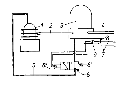
An air drier arrangement comprises an air compressor (1), an air drier (3) and
air conduits (2, 4). In order to obtain favourable working conditions for the
arrangement under different temperatures there is a switch-over valve (6) in a
separate signal air pipe (5) from the air drier to the compressor. This valve
is operable between a first position, giving a governor mode for the
arrangement, and a second position, giving an unloader mode for the
arrangement. The operation of the valve may be governed by a thermostat (9).


French Abstract

Un arrangement de dessiccateur d'air comprend un compresseur (1) d'air, un dessiccateur (3) d'air et des conduits (2, 4) d'air. Afin d'obtenir des conditions de fonctionnement favorables à l'arrangement à différentes températures, on a disposé une valve de commutation (6) dans un conduit (5) d'air à signal séparé du dessiccateur d'air au compresseur. Cette valve fonctionne dans une première position, donnant un mode régulateur à l'arrangement, et dans une seconde position donnant un mode de décharge à l'arrangement. Le fonctionnement de la valve peut être régulé par un thermostat (9).

Claims

Note: Claims are shown in the official language in which they were submitted.

5
CLAIMS
1. An air drier arrangement, comprising an air
compressor (1), an air drier (3), an air conduit (2) from
the compressor to the air drier and an air conduit (4) from
the air drier to an air tank or an air consumer,
characterized in that in a separate signal air pipe
(5) from the air drier (3) to the compressor (1) there is a
switch-over valve (6), operable between a first position,
in which air passes through the valve for accomplishing a
so called governor mode for the arrangement, and a second
position, in which the air pipe (5) from the air drier (3)
is closed and the air pipe to the compressor (1) is open to
the atmosphere for accomplishing a so called unloader mode
for the arrangement.
2. An arrangement according to claim 1,
characterized in that the valve (6) is a 3/2 way valve
spring-biassed to the first position.
3. An arrangement according to claim 2,
characterized in that the valve (6) may be brought to the
second position by means of an electrically energized
solenoid (6").
4. An arrangement according to claim 3,
characterized in that the energizing of the solenoid (6")
is governed by a thermostat (9).

Description

Note: Descriptions are shown in the official language in which they were submitted.


CA 02293809 1999-12-09
WO 98/57730 1 PCT/SE98/01170
AN AIR DRIER ARRANGEMENT
Technical Field
The present invention relates to an air drier
arrangement, comprising an air compressor, an air drier, an
air conduit from the compressor to the air drier and an air
conduit from the air drier to an air tank or an air
consumer.
Background of the Invention
It is generally known that it is important to keep
the inlet temperature to an air drier within a certain
span, for example +4 - +65°C, but actually as low as
possible. In many applications, when a so called governor
IS mode for the control of the arrangement is used, this leads
to problems with freezing in the air conduit between the
compressor and the air drier.
Namely, in the governor mode the air flow stops, when
the compressor is unloaded, leading under certain
circumstances to a temperature drop below the freezing
point. One advantage with this mode, however, is its energy
saving ability.
When on the other hand a so called on-line unloader
mode for the control of the arrangement is used, non-
pressurized air blows through said conduit from the
compressor and out to the atmosphere via the unloader valve
of the air drier, when the arrangement is unloaded.
From an energy conserving viewpoint this system has
disadvantages, but said conduit is always kept at an even
temperature, most often above the freezing point also at
low temperatures. Further, the conduit and the air drier
are blown clean from water that can~freeze to ice.
The Invention
The object of the invention is to combine the
advantages of the two well-known control modes described
above. This is according to the invention attained in that

CA 02293809 1999-12-09
WO 98/57730 2 PCT/SE98/01170
in a separate signal air pipe from the air drier to the
compressor there is a switch-over valve, operable between a
first position, in which air passes through the valve for
accomplishing a governor mode for the arrangement, and a
second position, in which the air pipe from the air drier
is closed and the air pipe to the compressor is open to the
atmosphere for accomplishing an unloader mode for the
arrangement.
In a preferred embodiment the valve is a 3/2 way
valve, which is spring biassed to the first position and
automatically may be brought to the second position by
means of an electrically energized solenoid controlled by a
thermostat device.
The Drawing
The invention will be described in further detail
below reference being made to the accompanying drawing, in
which the single Figure schematically illustrates an air
drier arrangement embodying the invention.
Detailed Description of Embodiments
2o An air drier arrangement shown in the Figure has an
air compressor 1 supplying pressurized air throgh an air
conduit 2 to an air drier 3, from which dried and cleaned
air is supplied in an air conduit 4 to an air tank (not
shown) and further to air consuming devices, for example in
a vehicle, in which the arrangement is mounted.
The compressor 1 and the air drier 3 are conventional
and are not further described. The air drier 3 is shown as
being of the single-tower type but may alternatively be of
the two-tower type.
The arrangement shown in the Figure is basically of
the known so called governor type, which means that the air
flow from the compressor 1 ceases in its unloaded state, i
a when no further air is needed.
For accomplishing this function there is a signal air
pipe 5 from the air drier 3 to the compressor 1.

CA 02293809 1999-12-09
WO 98/57730 3 PCTISE98/01170
By working in the governor mode the arrangement saves
energy in that the compressor 1 only works when more air is
needed. However, the damp air in the air conduit 2 between
the compressor 1 and the air drier 3 may under certain
circumstances freeze with serious consequences for the
arrangement.
By incorporating an electrically operated valve 6 in
the pipe 5 the arrangement may functionally be converted to
work in an on-line unloader mode when needed.
In such a mode non-pressurized air is transported
through the air conduit 2 from the compressor 1 to the air
drier 3 and out into the atmosphere through the unloader
valve of the air drier 3. In the unloader mode the
arrangement is more energy consuming but keeps the conduit
at a constant temperature preventing the air from freezing.
In addition, the conduit 2 and the air drier 3 are kept
clean from any water, which can freeze.
The valve 6 is a so called 3/2 way valve and is
biassed by a spring 6' into the position shown in the
Figure, in which air can be conducted from the air drier 3
through the air pipe 5 to the compressor 1. With the valve
6 in this position the arrangement will work in the
governor mode.
By electrically energizing a coil 6" of the valve 6
it is switched over into its second position, in which the
portion of the air pipe 5 closest to the air drier 3 is
closed and the portion of the air pipe 5 leading to the
compressor 1 is open to the atmosphere. With the valve 6 in
this position the arrangement will work in the unloader
mode .
The energizing of the valve coil 6" can be performed
manually, when the temperature drops under a certain level,
but the function can of course also easily be automated. An
example thereof is shown in the Figure.

CA 02293809 1999-12-09
WO 98/57730 4 PCT/SE98/01170
Electric energy is supplied to the valve solenoid 6"
through electric lines 7 from the battery of the vehicle
(if the arrangement is mounted on a vehicle). The lines 7
are drawn through a box 8 at the underside of the air drier
3 containing a thermostat 9, which is normally open but
which closes at a temperature below a certain value, for
example +4°C, for energizing the valve coil 6" and thus for
switching over from the governor to the unloader mode for
the arrangement.
l0 Other possibilities include the provision of a valve
with a built-in temperature sensor, for example a
bimetallic sensor. It would also be possible to make use of
an enclosed fluid, which is very volume-expansive with
rising temperature, at the valve.

Representative Drawing
A single figure which represents the drawing illustrating the invention.
Administrative Status

2024-08-01:As part of the Next Generation Patents (NGP) transition, the Canadian Patents Database (CPD) now contains a more detailed Event History, which replicates the Event Log of our new back-office solution.

Please note that "Inactive:" events refers to events no longer in use in our new back-office solution.

For a clearer understanding of the status of the application/patent presented on this page, the site Disclaimer , as well as the definitions for Patent , Event History , Maintenance Fee  and Payment History  should be consulted.

Event History

Description Date
Application Not Reinstated by Deadline 2006-05-17
Inactive: Dead - No reply to s.30(2) Rules requisition 2006-05-17
Deemed Abandoned - Failure to Respond to Maintenance Fee Notice 2005-06-17
Inactive: Abandoned - No reply to s.30(2) Rules requisition 2005-05-17
Inactive: Abandoned - No reply to s.29 Rules requisition 2005-05-17
Inactive: S.29 Rules - Examiner requisition 2004-11-17
Inactive: S.30(2) Rules - Examiner requisition 2004-11-17
Letter Sent 2003-04-02
All Requirements for Examination Determined Compliant 2003-02-28
Request for Examination Received 2003-02-28
Request for Examination Requirements Determined Compliant 2003-02-28
Letter Sent 2000-03-01
Inactive: Cover page published 2000-02-17
Inactive: First IPC assigned 2000-02-16
Inactive: Courtesy letter - Evidence 2000-02-01
Inactive: Single transfer 2000-01-28
Inactive: Notice - National entry - No RFE 2000-01-26
Application Received - PCT 2000-01-25
Application Published (Open to Public Inspection) 1998-12-23

Abandonment History

Abandonment Date Reason Reinstatement Date
2005-06-17

Maintenance Fee

The last payment was received on 2004-06-01

Note : If the full payment has not been received on or before the date indicated, a further fee may be required which may be one of the following

  • the reinstatement fee;
  • the late payment fee; or
  • additional fee to reverse deemed expiry.

Please refer to the CIPO Patent Fees web page to see all current fee amounts.

Fee History

Fee Type Anniversary Year Due Date Paid Date
Basic national fee - standard 1999-12-09
Registration of a document 2000-01-28
MF (application, 2nd anniv.) - standard 02 2000-06-19 2000-05-29
MF (application, 3rd anniv.) - standard 03 2001-06-18 2001-05-29
MF (application, 4th anniv.) - standard 04 2002-06-17 2002-05-24
Request for examination - standard 2003-02-28
MF (application, 5th anniv.) - standard 05 2003-06-17 2003-05-28
MF (application, 6th anniv.) - standard 06 2004-06-17 2004-06-01
Owners on Record

Note: Records showing the ownership history in alphabetical order.

Current Owners on Record
HALDEX BRAKE PRODUCTS AB
Past Owners on Record
SVEN-OLOF LARSSON
Past Owners that do not appear in the "Owners on Record" listing will appear in other documentation within the application.
Documents

To view selected files, please enter reCAPTCHA code :


To view images, click a link in the Document Description column. To download the documents, select one or more checkboxes in the first column and then click the "Download Selected in PDF format (Zip Archive)" or the "Download Selected as Single PDF" button.

List of published and non-published patent-specific documents on the CPD .

If you have any difficulty accessing content, you can call the Client Service Centre at 1-866-997-1936 or send them an e-mail at CIPO Client Service Centre.


Document
Description 
Date
(yyyy-mm-dd) 
Number of pages   Size of Image (KB) 
Representative drawing 2000-02-17 1 6
Abstract 1999-12-09 1 51
Description 1999-12-09 4 159
Drawings 1999-12-09 1 11
Claims 1999-12-09 1 32
Cover Page 2000-02-17 1 39
Reminder of maintenance fee due 2000-02-22 1 113
Notice of National Entry 2000-01-26 1 195
Courtesy - Certificate of registration (related document(s)) 2000-03-01 1 115
Reminder - Request for Examination 2003-02-18 1 112
Acknowledgement of Request for Examination 2003-04-02 1 185
Courtesy - Abandonment Letter (R30(2)) 2005-07-26 1 166
Courtesy - Abandonment Letter (R29) 2005-07-26 1 166
Courtesy - Abandonment Letter (Maintenance Fee) 2005-08-15 1 173
Correspondence 2000-01-26 1 14
PCT 1999-12-09 7 265
Fees 2004-06-01 1 43