Note: Descriptions are shown in the official language in which they were submitted.
CA 02294150 1999-12-17
WO 98/59219 PCT/GB98/01780
OPTICAL FIBRE BEND SENSOR
This invention relates to an optical fibre bend sensor.
A deformation of an optical fibre results in strain developing within the
fibre. Strains
can be categorised depending on the nature of the distortion which produces
them.
A longitudinal strain: a one-dimensional expansion or compression of the fibre
along
its length, is categorised as a scalar strain. A scalar strain by its nature
requires only
one parameter, the magnitude of strain along the axis of the stretch or
compression,
to characterise it. in terms of the strain tensor (s) this longitudinal strain
is the tensile
component szz.
If however a fibre is also free to deform in a transverse plane i.e. that
perpendicular
to the length of the fibre, further components of the general strain tensor
will have
effect. If the fibre is restrained in its position, tensile strain (s,~,
s~,~,) arises within a
compressed or stretched fibre in perpendicular directions to the longitudinal
strain
described above. This is known as transverse strain.
More generally, if the fibre is not fixed rigidly in location, one end of the
fibre may
then be displaced with respect to the other. Such a displacement occurs in
three
dimensions and results in a °bending" of the fibre. Both this bend and
three-
dimensional tensile strain require characterisation by both magnitude and
direction.
In the simple case of a bend with negligible fibre elongation, the induced
strain is
conveniently described in terms of the bend magnitude and plane of curvature.
This
curvature (K) has magnitude equal to 1/R, where R is the radius of curvature,
and
direction defined by the normal vector pointing towards the centre of
curvature.
Assuming a linear strain gradient across the bend then, in mathematical terms,
the
deformation developed in bending is formally equivalent to the transverse
strain
gradient : o,~u, where ~~ is the transverse gradient operator.
Optical fibre sensors for strain measurement are known in the prior art. An
optical
fibre is embedded in or surface-bonded to the structure to be monitored and
its
optical properties observed. The monitored structure is not limited to
engineering
applications e.g. aeroplane structures, building walls; optical strain sensors
have
CA 02294150 1999-12-17
WO 98/59219 PCT/GB98/01780
~2-
been found useful in the medical field. A number of external influences may
cause
strain to develop within a structure: applied stress (elasticity) and electric
field
(piezoelectricity) to name two. An optical fibre within such a strained
structure will in
turn experience the effects of such strains. Transverse strain components will
affect
the refractive index and longitudinal strain components will also stretch (or
compress) the fibre. In either case the optical path length of radiation
propagating
within the fibre is changed. Thus information pertaining to strain within the
monitored structure is manifest in the phase of radiation propagating within
the fibre
and is therefore extractable using interferometric techniques. Optical strain
sensing
is particularly attractive because interferometry offers an accurate detection
tool and
the sensitivity of optical properties to physical influences such as strain
and
temperature is high.
Temperature has a similar effect to strain on an optical fibre. Thermal
expansion will
change the length and refractive index of the fibre and additional strains may
also be
induced by the differential expansion of fibre and host material. Any optical
technique purporting to measure strain must make allowance for this cross-
sensitivity between temperature and strain.
A problem with prior art interferometric strain sensing techniques such as
that
described in patent application GB9606785.5 is that a single probe fibre
measures
only a scalar component of strain - the elongation of the fibre length.
Transverse
strain components are not measured and a general three dimensional contortion
of a
fibre is detectable only as a change in fibre length. Fibres have been
multiplexed
both in parallel and series in order to provide scalar strain measurements
across a
range of positions. From data gathered from an array of such single probes a
map
of strain gradient may be built up. However each probe intrusion inevitably
weakens
the structure being monitored. The intertace region will be subject to
increased
strain and there is a clear benefit to be had in limiting the number of such
interfaces.
Strain gradient measurements have been performed from sea-going vessels using
a
number of magnetic bearing sensors interspersed with depth sensors on a towed
sonar array. However such arrays are very bulky, occupying considerable
storage
space when not in use and such considerations limit the practical length of
the array.
CA 02294150 1999-12-17
-3'
Furtherrn-are magnetic bearing sensors as currently used are affected by
re m uence y
metallic structures on the sea bed as the array passes above.
An optical fibre sensing device sensitive to the degree of fibre bending is
disclosed In
US patens 4 443 698. The interference pattern developed between light
propagating
in two different cores of a muiticore fibre is used to monitor changes in the
bending of
the fibre. If two cores are used then a helical 90°-twist about each
other is
incorpvratnd over the sensing region. This allows the fibre to be sensitive to
bending
regardless of bend piano, but removes any capability of measuring bend
direction.
With three or more non-coplanar cores the need for such a twist can be
avoided. The
invention employs phase tracking techniques to follow varying bend parameters
in
order to all~nr deduction of unambiguous measurements. However, tracking
requires
access to one of the interferometer optical paths, a clear disadvantage for
_15 __ applications that ~evuire remofe~~ddrxssing-of-passive-se~sir~g-leng~ -
In~his-ca3e-.
bend direc~:ion information wilt be lost. Tracking will also be lost- if power
is not
continuously maintained.
There is a perceived need for non-intrusive shape sensing by means of bend
rneasurernerrt. Such a sensor would have many applications (n diverse fields.
in
robotics, kn~awledge of the absolute position of moving parts is essential.
This can be
deduced if directional bending of an integrated fibre can be measured. tn
medical
applications, any internal monitoring is safest with minimal intrusion from a
foreign
probe and, additionally, negligible generation of external electromagnetic
frelds,
28 Ughtweight positjon monttorln~.is essential _toQromote mobility._in
an_~~ificiat limb- -
Prior art optical strain sensors do not measure strain gradients and prior art
shape
sensors are overly bulky and generally rely on magnetic effects which have
neither
the accurac~~ nor immunity from environmental perturbation afforded by optical
measurement.
It is an object of thts Invention to provide an alternative form of bend
sensor.
Tn0 'd u5Sb8 b8910 ~ XY3 lQdl h?13;1'l~lh ~~3fl ~ 1 ~ 91 ( (~d16b_= ''111P-.0~
~
CA 02294150 1999-12-17
-4~
The resent i re me
assembly having first and second component cores and being arranged to convey
radiation to and from a sensor length comprising a bend sensing region of the
fibro
assembly and thereafiter to analysing means arranged to analyse radiation
output
from the fibre assembly,. characterised in that the fibre assembly
incorporates
coupling means for coupling radiation propagating from the sensor length In
the first
core to the second core for return to the sensor length, and reflecting means
arranged
to deftne the sensor length by at least partial reflection of radiation
thereat in both
cores, wh~3rein the reflecting means and coupling means are arranged to defrne
first
and second optical paths each of which traverses the sensor length in a
respective
one of the cores but not the other, and the analysing means is arranged to
disperse
interferograrns formed between radiation contributions which have traversed
the
optical paths.
Thin invention provides the advantages of acarracy and relatively non-
intrusive bend
measurement. Optical fibre assemblies can be produced with very small diameter
and embedding within a structure will thus result in minimal disruption of
that
structure. The apparatus is capable of determining bending of the sensor
length,
perhaps as a consequence of strain within an embedding structure, by
monitoring that
component of the bend in the plane of two fibre cores within the sensor
length.
Interferograms are formed between radiation propagating along two different
optical
paths, the optical paths differing within a specific region of the fibre. This
region, the
sensor length, may be only a fraction of the total fibre length. Generally,
bending this
sensing region will inevitably lengthen one core with respect to the other.
fnierrogation of this length differential by means of interferometry provides
an
accurate tool with which to measure bending. Moreover, deftning a sensor
length
down a potentially long ftbre downlead enables strains to be detected at a
localised
region remote from the radiation input end of the fibre. Thus the fibre
assembly can
be incorporated in, for example, a building wail, and strains developing in
the deep
interior of thE~ wall measured.
The first and second cores constitute a core pair and component cores of the
multicore fibre preferably comprise an arrangement of such core pairs; and the
cpp ~d etrSS68 t'8910 ~ Xdd ._ - lfldl Nb~!1'IY4V Y89Q t t -S i I 1~d166~
''1(lP-~~ .,
CA 02294150 1999-12-17
_g..
coupling ,means may accordingly be arranged to couple and reflect a portion of
ai ,
This provides the advantage of flexibility. The optical path difference
arising between
any core pair ~n be interrogated, and this embodiment therefore provides a
selection
of planes any of which may be the plane in which components of a general bend
curvature are measured,
The sensor may also include signal processing means arranged to extract
~ 0 interr'erogram phase variation from the dispersed interferograms and to
calculate bend
curvature ~:K) of the sensor length from the phase variation. This provides
the
advantage.; of speed and accuracy generally to be had from signal processing
power
in extracting a useful parameter, bend curvature x, from interferometric data.
_. lna pr~feXted-ambodima~,~-,~s~ctive-int2ffef-ograms -are-gertereted-from
radiation _
propagating within each core . pair, each interferogram arising from
differences in
respective i~irst and second optical path lengths; and the resultant
calculated bend
curvature (~;) is that component of bend curvature (xX, Ky) in a plane
containing the
sensor lenflth respective core pair. Moreover, the multicore fibre preferably
20 comprises ~~t least two core pairs contained in non-coincident planes,
thereby
enabling Calculation of absolute bend magnitude and orientation from
corresponding
in-plane components of bend curvature.
Such use of multiple core pairs enables bend plane to be advantageously
determined.
_ 25 ~ single _cor~ .pair ca~ba used. io_ obtain a measursmer~t-only-vf-~.
general three
dimensional ~,urvature projected onto a specific plane: that of the core pair.
However
measuremert of two non-coplanar projections, by means of two non-coplanar core
pairs, enables both the degree of curva;ure and the orientation of the plane
of the
curve to be deduced. Preferably, the two non-coplanar core pairs are contained
in
30 orthogonal planes. This maximises the likelihood of an accurate measurement
of any
bend direction within a general three-dimensional volume. (f more than two
core pairs
are used to measure multiple projections of a single curvature, magnitude and
orientation determination can be made with increased acxuracy.
600 'd ~ZbSS68 b89t0 ~X~d /Od l Nb3A'1dW ~~90 B t ~ S I ( Ibd) lib 1 ;'I!1P-0~
.. .. . ..~..... ..~. .... , r . . ~ 1 1\I
CA 02294150 1999-12-17
-6-
It is preferred that the cores wlthln each pair have unequal effective
refractive indices.
ses or w is i is am guous.
Although tend magnitude can be determined using a single core pair of equal
refractive index, such an arrangement cannot distinguish between a bend to the
right
and a bent' to the left i.e. there is no indication of which particular rnre
of the pair is
compressed, However, by arranging for the cores to be distinguishable in terms
of
optical path length, a means for determining which of the pair is compressed
is
provided. 1'he optical path difference measured by this embodiment of the
invention
is now dependent on the direction of the bend.
There are a number of known ways of producing unequal core effective
refractive
indices. For example, they may be produced during manufacture of the fibre,
i.e. by
using siightl;~ dli>ien~nt levels of doping per core, or after manufacture by
injecting high
intensity UV-radiation into one of the cores for a short time. The latter
technique has
t~. $~~.~~e~~e~x~~~_m altar way. ~ __. _ _
Bragg grating manufacture, and also offers mere flexibility.
The multicored fibre is preferably a bunched multiple rnonomode (BMM) fbre.
Such
fibres are known and comprise multiple fibre cores, each with an associated
cladding
"region". Each cladding region is smaller in cross-sectional area than would
be
required for typical cladding of cylindrical symmetry. This enables the cores
to be
more closely spaced than previously permitted, with regard to the requirements
for
avoiding croastalk. This in tum results in an overall reduction of the
diameter of a
multicore cat~le. This is advantageous to many applications of bend sensing in
which
- 25 - it. js desirable -to .mirllt'nise- the -disruptjon to a strudur~ under.
obsewatior~-by-intrusion
of a probe.
The component cores may be stress-induced highly birefringent (HiBi) cones.
This
provides the sensor with the capability of discriminating between the effects
of
temperature and strain.
Alternatively, the multicored fibre may be a photonic crystal frbre. This
again provides
the advantage of compactness. A photonlc crystal fibre is another example of a
cnn v etiSS68 ti991:0 ~ Xyd /ad I Na9A'1ELV ~~30 8 I ~ S t I Ibd166 , ''1(1P-
0~
CA 02294150 1999-12-17
-7-
m~rlticored fibre in which crosstalk can be kept to an axeptable level, but
overall fibre
In a preferred embodiment the fibre assembly is arranged to receive incident
broadband radiation and the analysing means is arranged to form a channelled
spectrum by dispersing interferograms formed between radiation propagating in
the
first and second optical paths as a function of wavelength. Suitable broadband
radiation mc~y be provided by a superluminescent diode, an Erbium Doped Fibre
Amplifier or a Praseodymium light source. These sources do not ah operate over
the
same wavelength range and appropriate detectors need to be used in each case.
Interferomet~ic techniques rely on measuring changes across the interference
pattern
as a function of the phase of the radiation forming it. It is therefore
necessary to scan
across a range of phase angles. Commonly optical path difference is scanned,
although ar; equivalent phase scan may be achieved by scanning radiation
--wavelength~us; wher~as~-Mid~relsenlnterfer~meter-~ca-ns-optical-path-
difference --
at constant wravelength, this embodiment of the invention scans radiation
wavelength
at constant cAptical path difference. The principal advantage of this
implementation is
that it requires neither an external reference path nor any motion of the
sensing
length, which would be impracticable in many applications, to compensate for
the
optical path difference introduced by the bend. This reduces the ancillary
apparatus
required to interrogate the sensing fibre once it has been embedded in a
structure.
Alternatively the sensor may also include a scanning Interterometer arranged
to
perform a scan of optical path lengths defined within and whereby
interferometer
2g - -cpt;~l pad-di~~races--compensate for the-.optical path diffar~nce-
t3e#ween. ~,~t-a~
second optical paths and the analysing means is arranged to disperse
interferograms
formed between radiation propagating in the first and second optical paths
(122, 724)
as a function the interferometer scan. The interferometer may be arranged to
perform
either a spatial or temporal scan.
The component cores may be distributed in a symmetrical arrangement within the
rnutbcore tfbr~:. The fibre is preferably less than 130wm in diameter.
900 'd ZbSS68 ti69I0~~yd IQdI Nb9~'lYW d~30 6(~SI II~d166 ~ "1~P-OS
CA 02294150 1999-12-17
~8~
The coupling means is preferably a tandem coupler. A tandem coupler is an
optical
transmits another proportion and at the same time couples the reflected
radiation into
another fibrr: core. These optical properties make the device eminently
suitable for
defining an optical path which encompasses two l5bre cores, such as is
required for
embodiments of this invention in which the sensing fibre length is addressed
via a
download in which the cores det7ne common beam paths.
The tandem coupler preferably incorporates a beamsplitter wherein the
beamsplitter
comprises a base and, non-coplanar with tfiis, respective pairs of planar
surface faces
for each cor~: pair wherein each planar surface faoe extends from the base
towards
" ' an apex and faces within each pair are mutually disposed at approximate
right angles.
Such a bearnsplltter conveniently provides in a single component the
reflection and
transmission characteristics required for the functioning of the tandem
caupler.
The multicor~.=d fibre may have four symmetrically oriented component cores
and the
beamsplitter' may comprise a square base, four triangular surface faces and an
apex
wherein each triangular face extends from one side of the square base to the
apex
and the perpendicular distance from the apex to the base is one half of the
distance of
one side of the base. Such a symmetric arrangement of cores means that the
same
accuracy of measurement can be had regardless of bend plane orientation.
Within the ta~~dem coupler the beamsplitter may be located intermediate to
first and
second planer microlens arrays wherein each miaelens array includes a
respective
microiens-located a focal-distance awayfrom each-component corn and .wherein
the
microlenses of each array are arranged in a common plane and the common planes
of each lens array are mutually parallel and parallel to the base of the
beamsplltter.
The micralenses in these arrays thus either produce a collimated beam from
radiation
exiting the cores, or couple collimated radiation into the fibre cores. This
aids
operation of the tandem coupler.
A further aspect of the invention provides a temperature sensor incorporating
a
muldcore fibre assembly having first and second component cores and being
ar,~anged to Canvey radiation to and frcm a sensor length comprising a bend
sensing
10A '~ ifSS68 ti8910~!idd /UdI M3A'1~W f~3U 61 ~ S1 ( lb~).66 , _~ne-o~.,
CA 02294150 1999-12-17
WO 98/59219 PCT/GB98/01780
_g_
radiation output from the fibre assembly characterised in that the fibre
assembly
comprises: a mufticored optical fibre having component cores which are
sufficiently
separated to counteract crosstalk; coupling means for coupling radiation
propagating
in a first core into a. second core of the fibre; and reflecting means
arranged to
reflect a portion of incident radiation; wherein the reflecting means and
coupling
means are arranged to define first and second optical paths within the fibre
assembly such that the paths have an optical path difference developed over a
sensor length section of the fibre within which the first optical path
corresponds to
radiation propagation in the first core and the second optical path
corresponds to
radiation propagation in the second core; and the analysing means is arranged
to
disperse interferograms formed between radiation propagating in the first and
second optical paths.
In another aspect, this invention provides a beamsplitter comprising a base
and,
non-coplanar with this, respective pairs of planar surface faces wherein each
planar
surface face extends from the base towards an apex and faces within each pair
are
mutually disposed at approximate right angles. Such a beamsplitter
conveniently
provides reflection and transmission characteristics which are appropriate to
various
optical applications.
The beamsplitter may be for reflecting a component of radiation propagating in
a first
core of a multicored fibre into a second core of the fibre, first and second
cores
comprising an opposite core pair, wherein each opposite core pair is aligned
with a
respective pair of beamsplitter planar surface faces such that an optical path
exists
from the first core to the second core via reflections from the planar surface
faces.
Preferably, the multicored fibre has four symmetrically oriented component
cores
and the beamsplitter has a square base, four triangular surface faces and an
apex
wherein each triangular face extends from one side of the square base to the
apex
and the perpendicular distance from the apex to the base is one half of the
distance
of one side of the base.
A tandem coupler may incorporate a beamsplitter in accordance with the above
description located intermediate to first and second planar microlens arrays
wherein
CA 02294150 1999-12-17
WO 98/59219 PCT/GB98/01780
_1p_
each microlens array includes a respective microiens located a focal distance
away
from each component core and wherein the microlenses of each array are
arranged
in a common plane and the common planes of each lens array are mutually
parallel
and parallel to the base of the beamsplitter. Such a tandem coupler has many
applications in devices in which it is required to define an optical path
encompassing
two fibre cores
In order that the invention might be more fully understood, an embodiment
thereof
will now be described with reference to the accompanying drawings in which:
Figure 1 is a schematic illustration of the components of the bend sensor.
Figure 2 is a cross section of the BMM fibre optic cable as illustrated in
Figure 1.
Figure 3 is a schematic illustration of a tandem coupler as used in the bend
sensor.
Figure 4 is a schematic illustration of a pyramid beamsplitter component of
the
tandem coupler.
Figure 5 is a schematic illustration of possible optical paths within the bend
sensor.
Figure 6 is an illustration of a hypothetical bend in the sensing length of
the bend
sensor.
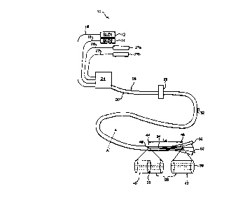
With reference to Figure 1, an optical fibre bend sensor of the invention for
making
vector strain measurements is illustrated generally by 10. The sensor 10
incorporates a pair of fibre pigtailed superluminescent diodes 12, 14
connected to a
respective pair of input monomode optical fibres 16, 18. Superluminescent
diodes
(SLDs) are particularly intense sources of broadband radiation. Suitable
diodes 12,
14 for use in this invention are supplied by Superlum Ltd., SLD-361/A-TO-SM,
with
wavelength range centred at 825 nm and FWHM bandwidth of 18 nm. The input
monomode fibres 16, 18 and two output monomode fibres 20, 22 are connected via
a fan-out connector 24 to respective cores of a 4-core Bunched Multiple
Monomode
(BMM) fibre assembly 26. Each output monomode fibre 20, 22 is also connected
at
CA 02294150 1999-12-17
WO 98/59219 PCT/CB98/01780
-11-
its opposite end to a fibre optic linked spectrometer 27a, 27b. Both fan-out
connectors and BMM fibres are known and described in Opto and Laser Europe,
issue 23, p29 (September 1995). The BMM fibre assembly 26 comprises a tandem
coupler 28; three 4-core BMM fibres: a first length 30, sensor downlead 32 and
sensor length 34; a semi-reflective splice 36 through the fibre assembly 26;
and a
silvered mirror 38 coating the fibre assembly 26 end. The cores of the first
length 30
of BMM fibre are those connecting the assembly to the fan-out connector 24. At
their opposite ends the first length 30 cores are optically connected to the
tandem
coupler 28. The sensor downlead 32 is the fibre section of the assembly 26
extending from the tandem coupler 28 to the semi-reflective splice 36 and the
sensor
length 34 extends thereafter to the silvered mirror 38 coating the fibre end.
The
sensor length 34 corresponds to a fibre of length LS at the extreme end of the
fibre
assembly, distant from the input connections. Enlarged views 40, 42 are shown
of
the 4-core BMM fibre assembly 26 at the semi-reflective splice 36 and the min-
ored
end 38 locations 44, 46. The splice 36 and mirrored end 38 exhibit negligible
absorption and have reflectances of approximately y and 1 respectively. The
BMM
fibre assembly 26 is flexible and fashionable into a variety of conformations.
Specifically, bending of the sensor length 34 occurs with respect to a pivot
point 48
located at the centre of the fibre at the position 44 of the splice 36. Any
bending of
the sensor length 34 about this pivot 48 is resolvable into components of
curvature
50, 52 in two mutually perpendicular planes, each component having a
respective
radius of curvature Rx, Ry (not illustrated). The orientation of these
components 50,
52 with respect to the BMM fibre cores will be described later.
A cross section of BMM fibre along AA' of Figurtg 9 is illustrated in Figure 2
and
indicated generally by 60. This structure is common to the three sections of
BMM
fibre, and the description herein is general and not referenced to any
particular
section. The fibre comprises first and second input 62, 64 and first and
second
output 66, 68 monomode cores embedded within a lower refractive index cladding
70. A dashed circle 72 with diameter equal to the maximum width of the BMM
fibre
illustrates the spatial extent of the fibre cross-section. The four cores 62,
64, 66, 68
are symmetrically oriented with nearest-neighbour spacing 74 of 44.2pm.
Opposite
inputloutput core pairs 62, 66 and 64, 68 have an intrapair separation 76 of
62.5~,m.
The cladding material is fused silica and core refractive index profiles are
defined
CA 02294150 1999-12-17
WO 98/59219 PCT/GB98/01780
-12-
within by germanium (Ge) doping. Two slightly different levels of Ge dopant
are
used to form the cores. The input cores 62, 64 therefore have slightly
different
refractive index profiles in comparison with the output cores 66, 68. The four
cores
62, 64, 66, 68 and cladding 70 are in a symmetrical four leaf clover
arrangement
with maximum diameter 78 of 125um. This core arrangement applies to the three
fibre sections of the fibre assembly 26. However, when specific reference is
made,
cores within the first length 30 are referenced with an additional symbol "a",
corresponding cores within the sensor downlead 32 are referenced with an
additional "b" and those within the sensor length 32 are referenced with an
additional
"c" e.g. 62c, 64c, etc.
Figures 3 and 5 are both illustrations at various sections of the fibre
assembly 26 in
a plane containing BB' which passes through one of the two opposite core pairs
62,
66.
Figurre 3 is a view in the plane of the first opposite core pair 62, 66
illustrating the
structure of the tandem coupler 28. The core pair 62, 66 comprises input 62
and
output 66 cores. The tandem coupler 28 is similarly structured in the plane
(not
illustrated) of the second core pair 64, 68 and performs the same coupling
function
. with regard to radiation propagating within these cores 64, 68. Components
referred
to previously are like referenced in this Figure. Specifically the tandem
coupler is
situated intermediate the first length cores 62a, 64a, 66a, 68a and the sensor
downlead cores 62b, 64b, 66b, 68b. Each first length core 62a, 66a shares an
optic
axis 80, 82 with the corresponding sensor downlead core 62b, 66b. First 80 and
second 82 optic axes of respective cores 62, 66 are illustrated in relation to
the
tandem coupler structure. The tandem coupler 28 comprises first 84 and second
86
Distributed Index - Planar MicroLens arrays (DI-PMLs) sandwiching a pyramid
beamsplitter 88. The input core optic axis 80 is aligned with first 90 and
second 92
microlenses, the first microlens 90 being part of the first DI-PML 84 and the
second
microlens 92 being part of the second DI-PML 86. Correspondingly, the output
core
optic axis 82 is aligned with third 94 and fourth 96 microlenses, these again
being
respective components of the first 84 and second 86 DI-PML. Each microlens 90,
92, 94, 96 is one focal length distant from respective first, second, third
and fourth
end faces 98, 100, 102, 904 of the cores 62a, 62b, 66a, 66b. The refractive
index of
CA 02294150 1999-12-17
WO 98/59219 PCT/GB98/01780
-13-
the DI-PML substrate material is nominally matched to that of the BMM fibre
cores
62, 66. The pyramid beamsplitter 88 has mutually perpendicular first 106 and
second 108 semi-reflective plane surfaces aligned at 45° to.respective
optic axes 80,
82. This orientation of beamsplitter surfaces 106, 108 has particular effect
on
radiation exiting from the download core pair 62b, 66b and incident on the
pyramid
beamsplitter 88 from the direction of the sensor download. A fraction of such
radiation is switched into the opposite core within the download core pair
62b, 66b
and its propagation direction reversed.
Figure 4 is a schematic illustration of the pyramid beamsplitter 88 viewed
through the
tandem coupler 28 towards the sensor download 32. In this view, sensor
download
cores 62b, 64b, 66b, 68b are surmounted by respective microlenses 92, 110, 96,
112 of diameter 40N,m. The pyramid beamsplitter 88 is sited above these
microlenses 92, 110, 96, 112. The beamsplitter 88 is a pyramid structure with
square base 114 with sides 108~m in length and apex 116 sited above at a
perpendicular height 54um. This defines four planar triangular side faces,
each
inclined at an angle of 45° to the exit faces of respective cores.
Figure 5 is a schematic illustration of possible optical paths within the
opposite core
pair 62, 66 and through intermediate optical components 28, 36. Light
propagating
within the second core pair 64, 68 follows similarly arranged paths but
rotated
through an angle of 90° about an in-plane axis along the length of the
BMM fibre
assembly 26. Components in this Figure which are also illustrated in
previously
described Figures are referenced as before. Such components include the tandem
coupler 28, sensor download 32 and length 34, semi-reflective splice 36 and
the
silvered mirror end 38. A bend axis 120 through the pivot 48 and parallel to
the
length of the BMM fibre assembly 26 provides a reference axis with respect to
which
a general bend of the sensor length 34 is defined. A bend is resolved into two
components of curvature 50, 52. One component 50 has a radius of curvature Rx
and is contained within the plane of the first opposite core pair 62c, 66c. A
second
component 52 (not illustrated) has a radius of curvature Ry and is contained
within
the plane of the second opposite core pair 64c, 68c. Two optical paths within
the
system are illustrated: a first 122 corresponding to that taken by radiation
which is
transmitted by the splice 36 while propagating within the input cores 62b, 62c
and
CA 02294150 1999-12-17
WO 98/59219 PCT/GB98/01780
~14-
reflected by the splice while propagating in the output cores 66b, 66c, and a
second
124 corresponding to that followed by radiation reflected by the splice 36 in
the input
cores 62b, 62c and transmitted by it in the output cores 66b, 66c.
Referring once more to Figures 7 and 2, the mode of operation of the bend
sensor
of the invention is as follows. The device 10 is capable of measuring strain
at the
sensor length 34 which results in a displacement bending of this length 34.
Broadband radiation from each SLD 12, 14 is coupled into a respective one of
the
pair of input monomode optical fibres 16, 18. Radiation propagates within
these
10 optical fibres 16, 18 and is coupled by the fan-out connector 24 into iwo
nearest-
neighbour cores 62a, 64a of the four core BMM fibre assembly 26. Radiation
propagation continues along the first length cores 62a, 64a, through the
tandem
coupler 28 and then within corresponding nearest-neighbour cores 62b, 64b of
the
sensor downlead 32 to the semi-reflective splice 36. At the splice 36, a first
component of the radiation is transmitted along the sensor length 34 to the
silvered
mirror 38 coating the fibre end. This component of radiation is then reflected
by the
mirror 38 and returned through the splice 36 to the tandem coupler 28. A
second
component of radiation is reflected from the splice 36 directly back along the
sensor
downlead 32 to the tandem coupler 28. Whilst propagating along this path and
in
_ the BMM fibres 30, 32, 34 of the BMM fibre assembly 26, radiation is
substantially
contained within the input cores 62a,b,c; 64a,b,c. The tandem coupler 28 is
arranged to transmit a first fraction of the radiation incident on it from the
sensor
downlead 32 and reflect a second fraction. The first fraction is transmitted
to the first
length 30 of the BMM fibre assembly 26, maintaining waveguide core occupancy.
That is, radiation within one core 62b, 64b of the sensor downlead 32 is
transmitted
to the corresponding core 62a, 64a of the first length 30. The second fraction
is
coupled into the second (output) core 66b, 68b of each respective opposite
core pair
62b, 66b; 64b, 68b and reflected back along the sensor downlead 32. This
reflected
fraction thus executes a second pass through the sensor downlead 32 and sensor
length 34 sections of the BMM fibre assembly 26, this time following similarly
structured optical paths but confined to different cores. On its subsequent
return to
the tandem coupler 28, a portion of this reflected fraction is transmitted
through the
tandem coupler 28, maintaining waveguide core 66, 68 occupancy. This is the
fraction of incident radiation which contains information about the various
optical
CA 02294150 1999-12-17
WO 98/59219 PCT/GB98101780
-15-
path lengths within the cores of the BMM fibre assembly 26 which are of
interest to
this invention. A detailed description of the information contained and its
extraction
by interferometry will be provided later. Radiation propagating from the
tandem
coupler 28 in the output cores 66a, 68a of the BMM fibre assembly 26 is
coupled by
the fan-out connector 24 into respective output monomode fibres 20, 22.
Radiation
output from each monomode fibre 20, 22 is analysed by a respective fibre optic
linked spectrometer 27a, 27b.
The internal structure of the BMM fibre components of the assembly 26 is
illustrated
in Figure 2. Core separation 74 and dimensions, and cladding dimensions 76 are
such as to avoid siCnificant crosstalk between radiation propagating in each
core 62,
64, 66, 68 and ye~. maintain an acceptably small fibre diameter 78 overall. An
external diameter cf 125~m lends itself to a number of applications in which
the
disturbance caused by sensor intrusion should be minimised.
Referring now to F.gure 3, the operation of the tandem coupler 28 is as
follows. This
description refers cr.ly to radiation propagating within the first opposite
core pair 62,
66. Radiation aisc propagates in the second opposite core pair 64, 68 in a
symmetrically equal alent arrangement. However there is minimal interaction of
radiation between ~:e two pairs and for reasons of brevity only the first core
pair 62,
66 is refer-ed to. ;:onetheless, the complete embodiment of this invention
does
include a symmetrically equivalent arrangement in a plane perpendicular to
that of
the first core pair lr2: ~ parallel to the BMM fibre axis.
Radiation propaga~~~a in input core 62 is reflected from the splice 36 andlor
the
min-ored end 38 a:.~ directed back along the sensor downlead 32 towards the
tandem coupler 28. This radiation is substantially contained within one core
62b of
the opposite pair E~, , 66b and is incident on the tandem coupler 28 at the
fibre end
face 100. Radiaticr. a collimated by the second microlens 92 of the second DI-
PML
86 and directed tc~~. girds the first semi-reflective plane surface 106 of the
pyramid
beamsplitter 88. C~ : component of this radiation is transmitted to the first
microlens
90 of the first DI-F;~~_ 84 and the second component is reflected towards the
second
semi-reflective plar~ surface 108 of the pyramid beamsplitter 88. At this
second
surface 108 refle~n and transmission again occur and a component of the
CA 02294150 1999-12-17
WO 98/59219 PCT/GB98/01780
-16~
propagating radiation is reflected towards the fourth microlens 96 of the
second
DI-PML 86. This component is then focused by the fourth microlens 96 and
coupled
into the opposite core 66b at its end face 104 to propagate back along the
sensor
downlead 32. Correspondingly, radiation propagating from the sensor downlead
32
in the output core 66b of the core pair will be partially transmitted to tile
corresponding core 66a in the first length 30 and partially reflected back
along the
sensor downlead 32 confined in the input core 62b. Radiation traversing the
tandem
coupler 28 in a direction from the first length 30 to the sensor downlead 32
will be
pariyally transmitted, maintaining core occupancy. Other components are lost
from
the system. Thus the overall function of the tandem coupler 28 is equivalent
to that
of a flossy) semi-reflective surface with a transmission coefficient r~~ and
unidirectional reflection coefficient p,~, with the additional property that
reflection
results not only in propagation direction reversal but also in a switch in
confinement
between the cores of an opposite core pair 62b, 66b. If the transmission and
reflection coefficients of each surface plane 106, 108 of the beamsplitter
pyramid
are rp and pP respectively, then rr~ = rp and pry = pp2 or 0, depending on
direction of
propagation.
Referring to Figure 5, the principle behind the operation of this invention is
outlined.
. As before, the description is limited only to propagation along the first
opposite core
pair 62, 66 although symmetrical optical paths are followed in a perpendicular
plane.
Radiation enters the system propagating along the first length 30 within the
input
core 62a of the first opposite core pair 62a, 66a. It is transmitted through
the
tandem coupler 28, propagates along the sensor downlead 32 in input core 62b
to
the splice 36. There are two optical paths 122, 124 through the system
containing
information pertinent to this invention and they diverge at this point. The
first optical
path 122 is that followed by radiation transmitted by the splice 36. This
component
propagates in input core 62c to the mirrored end 38 where it is reflected and
propagates back to the splice 36. The second optical path 124 is that followed
by
radiation reflected when first incident on the splice 36. Both components
therefore
propagate from the splice 36 back along the sensor downlead 32 in input core
62b
again following a common path. On reaching the tandem coupler 28, both
components are reflected and coupled into the output core 66b of the core pair
62b,
66b. Still following a common path, the components propagate for a third time
along
CA 02294150 1999-12-17
WO 98/59219 PCT/GB98/01780
-17-
the sensor downlead 32, on this occasion confined to a different core 66b,
66c. At
the splice 36 the optical paths 122, 124 again diverge. In this core 66b, 66c,
the first
optical path 122 is followed by radiation reflected at the splice 36 and the
second
optical path 124 is followed by transmitted radiation. The component of
radiation
following this second optical path 124 is reflected by the mirrored end 38 and
returned to the splice 36. Propagating from the splice 36, back towards the
tandem
coupler 28 the components again follow a common path. They are both
transmitted
by the tandem coupler 28 and exit the system confined in the output core 66a.
Radiation output from the system in this core 66a is subject to
interterometric
analysis by the fibre optic linked spectrometer 27a. The difference therefore
between these two optical paths 122, 124 is that the first 122 requires two
passes of
the sensor length 34 in the input core 62c and the second 124 requires these
passes to be made in the output core 66c. A bending of the sensor length 34
inevitably results in a lengthening of one core with respect to the other of
the pair
62c, 66c. The features of an interterence pattern generated from radiation
following
the first optical path 122 and radiation following the second optical path 124
is
dependent on the optical path difference (OPD) between the two paths 122, 124.
The OPD arises almost entirely from the different physical path lengths in the
two
separated cores 62c, 66c in the bent sensor length 34. This OPD is therefore
indicative of the degree of bending of the sensor length 34 in the plane of
the
opposite core pair 62c, 66c. Two perpendicular components of a sensor length
bend are measured in this embodiment of the invention - one in each plane
defined
by an opposite core pair. From this data the degree and orientation of the
bend is
deduced. Because the refractive index of the input core 62c is slightly
different from
that of the output core 66c, the OPD is dependent on the direction of a bend
i.e.
whether the input core 62c is compressed or stressed with respect to output
core
66c. Thus bend handedness is also measured by this invention.
Figun' 6 is a representation of the effect of bending the sensor length 34.
Bending
is illustrated as being in the plane of Figure 5 i.e. this Figun' is a section
through the
sensor length 34 in the plane of the first opposite core pair 62c, 66c. The
bend is
described in terms of its radius of curvature Rx. In bending, a central axis
130 of the
sensor length 34 provides a reference length (LS) and a reference strain which
is
taken to be zero. Relative to this, in the specific bend illustrated, the
input core 62c
CA 02294150 1999-12-17
WO 98/59219 PCT/GB98/01780
~18-
is compressed and experiences a strain of -sA and the output core 66c is
stretched to
a strain +sB. The cores 62c, 66c are located a distance rfrom the central axis
130.
Referring to Figures.2 and 6, the effect of a general bend of a multicore
optical fibre
is detailed below. Symmetrically distributed waveguide cores will be either
compressed or stretched longitudinally as one side of the fibre is lengthened
with
respect to the other. This general distortion can be resotved into components
consistent with the symmetry of the core distribution. In this embodiment a
four-core
fibre is used and appropriate bend components are those in the two planes
containing opposite core pairs. Figure 6 is an illustration of the component
in the
plane of a cross-section taken along BB' in Figure 2. Optical elements within
the
fibre assembly are arranged such that radiation propagating in one core 62, 64
of
each component plane is coupled into the other core 66, 68 within that same
component plane. In this way any optical path difference between the two cores
62,
66 arising from a general fibre bend is evidenced in an interference pattern
formed
from radiation components traversing different paths. This interference
pattern is
used to extract the sensor length bend component within the plane defined by
the
coupled cores. Defining the component planes by well-separated cores is
advantageous because of the increased optical path length differential
resulting from
a bend.
The sensor length bend component in the plane defined by coupled cores 62, 66
has general radius of curvature RX. The central axis 130 of the sensor length
34
provides a reference length and strain of zero relative to which the strain at
each
core is measured. In this embodiment of the invention any tensile strain and
resultant change in the overall fibre sensor length LS is not detected.
Changing LS
will affect both optical paths 122, 124 equally and, although therefore this
parameter
is not constant, its variation is irrelevant to the analysis below.
One skilled in the art will appreciate that longitudinal strain may be
measured by a
prior art technique, if required, although it is not necessary for many
applications
envisaged. Furthermore prior art techniques such as patent application
PCT/GB94/01388 to measure longitudinal strain require interrogation of a
sensor
length against an external reference. !t is an advantage of this invention
that an
CA 02294150 1999-12-17
WO 98/59219 PCT/GB98/01780
_1g_
external reference is not needed either to provide a complementary path
difference
or to facilitate scanning of an optical path difference, which cannot be
achieved
within the sensor length. Once an external reference is incorporated, it is a
simple
extension of a prior, . art technique to interrogate each core of a multicore
fibre
independently, derive values of longitudinal strain at each core and thereby
determine bend magnitude and orientation. It is to be appreciated that, as
already
part of the prior art, longitudinal strain measurement is not central to the
inventive
concept behind this invention and will be omitted from this description for
clarity.
The strain (sB), defined as the ratio of elongation to unstrained length,
experienced
by the output core 66c is thus:
~Rx + r~a - Rxa r
8 = =-~rx
s Rxa Rx x
where a is the angle subtended by the sensor length bend and ~:x = 1lRx is the
bend
curvature. Similarly the strain (sA) experienced by the input core 62c is
r
EA ~ _- ~ _rxx
Rx
Strain and temperature affect both the length (L) and the effective refractive
index
(rl) of a waveguide core. However, in this invention the cores are
sufficiently close
that, in all except large transverse thermal gradients, they effectively
experience the
same environmental temperature. Thus any optical path difference which is
measured by interference techniques can, to a good approximation, be
attributed
purely to the effect of strain. In general
L = LS {1 + s), and
~1=~lo+~E
where r~o and L$ are the effective refractive index and length respectively of
the
unstrained waveguide sensor length 34 at its environmental temperature and ~E
is
CA 02294150 1999-12-17
WO 98/59219 PCT/GB98/01780
-20-
the contribution to effective refractive index arising from strain s. The
effective
refractive index in a strained environment is, more informatively:
where the subscript ~ has been included to indicate explicitly that rl refers
to the
effective refractive index experienced by monomode propagation within a
waveguide
core, and the dependence of these effective refractive indices on wavelength
~, has
also been indicated. The parameter K is a strain-optic coefficient which is
given by
K = 2 ~(1- ~.~p~2 - ~, p,~ ~a 0.103 (for fused silica)
where p", p,2 are Pockets coefficients and ~, is Poisson's ratio. Both length
and
refractive index changes affect the phase (~~o~e) of radiation within the
core:
~~«e = ~~' ~(~)~1~~(~, E)
Equation (1) therefore describes mathematically the phase of radiation as it
propagates within a monomode waveguide core. A detailed description of the
extraction of phase information, and hence strain, from an interference
pattern
generated by this invention is given below with reference to Figure 5. Also
presented are further details of apparatus design.
Radiation input to the system and propagating down first input core 62 can be
represented at time t by the analytic signal
E(w, X) = Fo e~(roo+~(~.=))e~r
CA 02294150 1999-12-17
WO 98/59219 PCT/GB98/01780
~21-
where E is the radiation instantaneous electric field, ~o the angular
frequency, z the
distance travelled along the guide core, ~o the initial phase and ~ the phase
variation
with distance. In particular
~ _ ~'-' x OPL = w zt~~{a,~)
c c
where OPL is the optical path length traversed, rl~ the effective refractive
index of
the fibre core and c the speed of light.
Radiation transmitted for a first time through the tandem coupler 28
propagates
along the first input core 62b to the splice 36 where it is split into two
components.
The first component (indicated by subscript ~, following the first optical
path 122, is
transmitted by the splice 36 and then reflected at the mirrored end 38. The
second
component (indicated by subscript R), following the second optical path 124,
is
simply reflected. The splice 36 transmits and reflects incident radiation with
transmission and reflection coefficients ~S and ps respectively and the
mirrored end
38 reflects with reflection coefficient pm. For convenience in describing the
theory of
the invention any phase change experienced by all radiation components as a
result
of traversing a common path will be referred to generically as ~P. Thus the
two
components which are reflected back along the input core 62b towards a second
passage through the tandem coupler 28 are represented by the signals:
ER ~ PszroEo e~4'°
FT ='~sPm'~tcEo e'~'°e'~~
where, for reasons of clarity, the common time-dependent term e'°'' is
not shown and
initial phase ~o has been incorporated into ~~P. The factor of zr~ arises from
the first
pass through the tandem coupler 28. The phase ~A is the additional phase
change
developed in the transmitted component due to the optical path length
associated
with iwo passages (one in each direction) through the sensor length 34 in the
input
core 62c. This optical path length is given by 2LSs2n~s2.
CA 02294150 1999-12-17
WO 98/59219 PCT/GB98/OI780
-22-
On reaching the tandem coupler 28, the radiation components of interest to
this
invention are those which are then reflected into the output core 66b,
experiencing a
reflection coefficient pt~. Following two optical paths 122, 124 these
components
propagate to and are incident on the splice 36 for the first time in the
output core
66b. At this point, each component is split into a further two components: one
(R) is
simply reflected by the splice 36; the other ('n is transmitted by the splice
36,
reflected by the mirrored end 38 and then again transmitted through the splice
36.
On the second return along the sensor downlead 32 to the tandem coupler 28
there
are thus four distinct components of radiation:
ERR = PtcPsztcEo e~ø'°
ErR = PtcPs'~sPm~rcFo e~~e'~"
ERr = PtczSPmPsitcEo e~'"e'oe
Err ~ Ptc'~sPtZn'ztcEo a ~'9e'~"era
75 -
where ~B is the phase difference introduced by traversal of the optical path
between
the splice 36 and mirrored end 38 within the output core 66c. Since two
passages of
the sensor length 34 are made, this optical path length is given by 2LSss~~ss.
Thus when output from the system, after a final traverse of the tandem coupler
28,
the total output signal can be represented by a supposition of four fields:
Eout - tt PtcFo el(~~~~'~2>wt ~Ps 't' PsPm~s e~"'t' PsPm~s e~e'E Pmts
e~~~~~~e)~ (2)
This signal is input to the fibre optic linked spectrometer 27a. Information
concerning the bend of the sensor length, as described in Equation (1), is
contained
within the phases of the four components of Equation (2). This is extracted
using
interference techniques. Formation of a coherent interference pattern is
governed
by the mutual phase difference between the four components and their
subsequent
detection optical bandwidth. This embodiment of the invention is arranged such
that
the effective coherence length on detection is less than twice the sensor
length (LS)
but greater than the largest difference in optical path length at the
extremity of bend
CA 02294150 1999-12-17
WO 98/59219 PCT/GB98/01780
- 23
curvature. In this way the first (ps ~ and fourth (pm~$ e'~~"+~H ~ ~
components of
' Equation (2) do not interfere with any other component and the second
~PsPmzs e~" ~ and third (pspm~s eye ~ components interfere on detection
throughout a full range of practical bend curvatures.
The fibre optic linked spectrometer 27a incorporates an array of pixel
detector
elements. The coherence length {h,) of radiation incident on the ith pixel is
given by
c
-~-
0v;
where 7b; is the central wavelength of detection, 0~,; the detected optical
bandwidth
and Ov, the frequency spread of the detected signal. To satisfy the
interference
requirements above, the restriction on optical bandwidth per pixel of the
detector
array is subject to the condition:
2' OPLSA - OPLSB I~ < I~; < 2 ~OPLSA .~ OPLSB ~ {3)
where OPL is the optical path length and subscripts SA and SB refer to
propagation
through the sensor length 34 in input 62c and output 66c cores respectively.
In the
embodiment herein described, this condition is satisfied by the commercially
available Ocean Optics PC1000 fibre-linked spectrometer.
Only one interference pattern is generated in an embodiment of the invention
which
satisfies the condition of Equation (3) above. The intensity pattern across
such an
interferogram is represented by:
4 p2 ~ i(~o+~qa ~ i~ur ( ( 4 4 8 Zp2 4 !~a ire 2
dour = arc rc~o a a 2 j Ps + Pm~a '~ Ps mZs le + a
This can be written in terms of the transmittance (T= T2) and reflectance (R =
p2) of
the splice 36 and mirrored end 38:
CA 02294150 1999-12-17
WO 98/59219 PCT/GB98/01780
-24-
!o"t =T~Rr~lo~Rs +Rm s4 +2RSRm s2~1+cos~~A -~e)~~
The R and T values of the splice 36 and mirrored end 38 in the embodiment
described are RS = y , TS = % and Rm = 1. These values maximise the depth of
the
[1 + cos {~A - ~B)) modulation. In this embodiment therefore, the
interferogram
intensity variation is given by
fo", = 2.05 + cosh
where ~ _ ~A - Vie.
Substituting Equation (1) for the values of ~A and ~B, the effect of fibre
bending on ~
can be written:
LS~(1+EA)(~A(~)-EAICTIA(~))-~1+eB~~Tle(~)-~eK~le{~)
4~, LS~~'1A(~)-~1B(~)~+EA(riA(~)-K~la{~))
- Ee ~rle(~) - Krls(~)~- K~EArIA O) - ~s~le(~)
Second order terms in s are at least four orders of magnitude less than first
order
terms and, to a very good approximation, can be neglected. The resultant phase
difference arising from a bend curvature K is thus:
~{LS,x,7~~= ~ L.S~I;~IA(~)-~le(~)~
(4)
- rKx[UA {~) + ~18(~))- K~~IA (~) + ~1s(~)~~
and the generated interferogram has intensity variation
~o"r(LS, K, ~,~ « 2.05 + cos ~(LS, x, ~.}
The slightly different doping levels in the input 62c and output 66c cores
enables the
direction of bend curvature within this plane, i.e. whether input core 62c is
compressed or extended, to be determined. Different doping levels ensure that
CA 02294150 1999-12-17
WO 98/59219 PCT/GB98/01780
-25-
~lA(~) ~ ~te(~), ~(LS,K,~.) # ' ~(LS,-K,~.) and so la"~ (Ls,K,~) $ logic (Ls,-
K,~). If rlA > rle, a
positive curvature (K) will result in an expanded fringe system in comparison
with a
negative curvature. The system 10 is calibrated initially over a range of both
positive
and negative bend curvatures and it may become apparent at this stage that the
frequency ranges of cosine fringes in the two regimes do not overlap.
The superluminescent diodes 12, 14 inject broadband radiation into the system
10
and broadband interferograms are generated. These interferograms are detected
using the fibre optic linked spectrometers 27a, 27b. In the plane defined by
core
pair 62, 66, radiation output from the end of the BMM fibre assembly 26 is
dispersed
and focused by the spectrometer 27a onto a linear detector array as a
channelled
spectrum. In this way one point (constant optical path difference) of the
interferogram is sampled over a range of wavelengths. Another sampling
technique
which provides alternative embodiments of the invention derives from scanning
the
sensor length LS. However scanning sensor length presents additional
considerations which may not be acceptable in some applications. Practically
it is
not possible to change the length of the sensor length 34, as used in the
specific
embodiment employing wavelength scanning. An additional optical path element
of
variable length, such as that provided by a Michelson interferometer, must be
included in the system as an external compensation far the optical path
difference
introduced by the bend. Interferograms may be produced either spatially or
temporally. Spatial multiplexing of an interferogram allows for the
possibility of fringe
tracking. This involves continuous monitoring of a portion of the
interferogram the
motion of which is attributable to changes in the bend curvature of a sensing
element. This constitutes a convenient monitoring technique which presents
readily
interpretable results, without the need for complex signal processing.
In the specific embodiment presented herein, the interferogram is sampled as a
function of ~, by the spectrometer 27a. The sampling is discrete (at the
position of
each pixel of the detector) and results in a series of interferogram
intensities
measured at each pixel position. The detector has substantially identical
pixels
whose positions in the array increment linearly with wavelength. The measured
channelled spectrum function is termed I(p,) where pr represents the position
of the
ith pixel. A Fourier transform of this function is calculated to give the
function !(q,),
CA 02294150 1999-12-17
WO 98/59219 PCT/GB98/01780
-26-
where g, represents inverse pixel position (spatial frequency). Noise within
the
system appears at the high frequency end of this !(q,) spectrum. DC background
bias and source spectral profile give rise to a large peaks at the low
frequency end.
A bandpass filter is therefore applied to I(q,) to select an intermediate
range which
contains usable information I'(q,). An analytical representation of the
interferogram
is then derived from I'(q,) by taking the inverse Fourier transform to Re
[I'(p,)], the
real part of the representation, and then the Hilbert transform of this to Im
[!'(p,)], the
imaginary part. The analytical representation is thus:
I'(p,) = Re [I'(p;)] + i x Im [I'(p,)] = a(p,) e'~~'~
For each component sampled along the detector array a value of ~(p;) is
calculated
from the argument of the analytic signal I'(p;). The phase is unwrapped to
remove
2n discontinuities and a series of phase values across pixel positions are
obtained.
In this embodiment of the invention the wavelength variation across the
broadband
source output is approximately from 810nm to 840nm i.e. ~ 3.64%. The inverse
wavelength range is therefore to a first order approximation, also broadly
linear and
no significant error will arise in taking pixel position to represent inverse
wavelength.
In fact this error is reduced still further by the bandpass filter which
removes higher
order components of the expansion. Thus unwrapped phase variation with inverse
wavelength is effectively obtained by this signal processing technique. This
phase
variation can then be fitted to a polynomial. For the purpose of bend
curvature a first
order least-squares fit will generally be sufficient.
The bend curvature {KX) may be extracted from the phase variation with inverse
wavelength using Equation (4) above. The other parameters of Equation (4):
rlA(~,),
rle(~.), r, K, and LS can be used directly if their values are known but
generally it will
be more accurate to allow for system errors and irregularities and pre-
calibrate the
measurements for a range of known bend curvatures.
By an analogous route the value of Ky is extracted from interferometric
measurement
of radiation input to and output from the second opposite core pair 64, 68.
Together
measurement of the magnitude and direction of both KY and KX provides the
information necessary to deduce total bend curvature and orientation.
CA 02294150 1999-12-17
WO 98/59219 PCT/GB98/01780
_27_
Further information than solely bend curvature may be extracted from the phase
variation with inverse wavelength if a higher order polynomial fit is made.
For
example, the second order coefficient may be used to discriminate between
temperature variation and strain as known in the prior art and described in
patent
application PCT/GB94/01388.
It is not necessary to use a 4-core BMM fibre in the assembly 26. The fibre
may
contain any arrangement of core pairs which enables bend components to be
measured in each core-pair plane. Neither is it necessary to have a
symmetrical
arrangement of cores. An alternative embodiment of the invention provides for
a 6-
core photonic crystal fibre to replace the BMM fibre 26. Such fibres are
manufactured by close packing of cylindrical units and therefore have 6-fold
symmetry at the fibre entry/exit faces. Multiple cores are defined by
fabricating
waveguides at appropriately positioned cylindrical units. Waveguide core
positions
must be well separated to reduce crosstalk and well cladded. In a 6-core
symmetric
embodiment components of bend curvature are measured in three planes of
opposite core pairs. Three bend components provide for more accurate
measurement of vector strain. In a 3-core embodiment three core-pairs in three
planes are again available but cores must provide for simultaneous operation
as
both input and output cores or application is limited to bends which vary
slowly with
time.
Photonic fibres allow for waveguide cores to be more closely spaced before
cross-
coupling effects occur in comparison with the BMM fibres described herein.
This
allows the overall diameter of the fibre to be reduced, lowering further the
disruption
caused by sensor intrusion.
The embodiment described illustrates an application of the invention to strain
measurement. However, as noted above, temperature has a similar effect to
strain
on light propagating within a fibre. These multicored fibres can thus be used,
in an
' analogous fashion, to measure temperature gradient. Such a measurement
assumes that the optical path difference between two cores of a pair arises
entirely
from the temperature difference in the environments of each core. Note that as
the
CA 02294150 1999-12-17
WO 98/59219 PCT/GB98/01780
-28'
cores in both BMM fibres and photonic crystals are very closely spaced, these
fibres
are primarily applicable to measurement of large temperature gradients.
Another adaptation provides capability for simultaneous measurement of bend
and
temperature. In this embodiment, the cores of the BMM fibre exhibit high,
stress-
induced birefringence (HiBi cores). This provides a means, as described in
patent
application 689606785.5, for sensitive discrimination between the effects of
strain
and temperature on fibre optical properties. A change in temperature modifies
induced stresses in a HiBi core and so affects its birefringence. However,
high
birefringence shields the core from transverse stresses and so is
substantially
unaffected by stress. Thus both bending and temperature modify the length of
the
cores whereas only temperature affects the birefringence. Determination of
these
unequally-affected parameters allows discrimination between the effects of
temperature and strain. The optical configuration and interrogation schemes
are
unchanged from those illustrated in Figure 9. Radiation is coupled into the
HiBi
cores in such a way as to equally populate both polarisation eigenmodes. Each
physical optical path 122, 124 with a HiBi core pair is resolved into two
optical paths,
a "fast" and a "slow" channel, each populated by one eigenmode. Two
interferograms are therefore generated for each measurement, and are analysed
in
known manner to separate the contributions of temperature and strain.