Note: Descriptions are shown in the official language in which they were submitted.
CA 02294183 1999-12-21
WO 99/60276 PCT/US99110334
FAN BLADE MOUNTING
BACKGROUND
The present invention relates generally to large air-moving fans. and more
particularly to
an improved means for mounting fan blades on a rotatable hub.
Large fans having diameters ranging from about one to ten meters or more are
commonly
used for moving air through cooling towers, heat exchangers and the like. A
typical fan in such
an application may have a diameter of about five meters and anywhere from two
to eighteen
airfoil shaped blades coupled to a rotatable hub. For light weight and
economy, such fan blades
may be fabricated from thin aluminum alloy sheets. The sheet metal is bent to
provide a rounded
leading edge, with the upper and lower surfaces of the blade converging toward
a trailing edge
where they are riveted or spot welded together. The chord line of the airfoil
blade at the tip of
the blade ranges anywhere from about fifteen to forty centimeters, and the
maximum thickness
of the airfoil ranges anywhere from about two to fifteen centimeters.
As used herein, the downstream face of the fan and blades is referred to as
the upper face
and the upstream face is referred to as the lower or cambered face. This is
because the largest
of the fans are primarily used in cooling towers or the like where they rotate
about a vertical axis.
Such fans are also used where the fan rotates around a horizontal axis.
Such large air-moving fans operate within a circumferentially extending
shroud, which
is very often not quite circular and may not be exactly concentric with the
axis of the hub.
Therefore, when a fan is installed, the blades and/or shroud are adjusted so
that the blades clear
the inside of the shroud by one or two millimeters at the closest approach,
however, the blades
may be about twenty millimeters (or greater) away from the shroud at the
widest gap.
The blades of large fans of The Moore Company of Marceline, Missouri, the
assignee of
the present application, are mounted to a central hub, preferably by a
connection that permits
limited vertical (parallel to the axis of rotation) motion. Thus, the blades
may "droop'' slightly
when stopped. but generally extend radially from the hub during rotation. The
connection
between the inner ends of the blades and the hub is critical since it is a
possible source for failure
by fatigue cracking. Light weight and reliability are important. It is
desirable to provide a
mounting for blades which has minimum susceptibility to fatigue failures.
SUMMARY OF THE INVENTION
The fan blade mounting system according to the present invention generally
includes a
plurality of radially extending hub struts. a blade root member pivotally
coupled to an end of
each hub strut for receiving a blade skin. and a tube end insert located
between each blade root
member and its corresponding hub strut. A pair of resilient mounts are
utilized in the blade root
member to effectively pivotally couple the blades to the hub, thus relieving
most of the vertical
bending moment transferred to the hub and eliminating critical frequencies
associated with the
CA 02294183 2003-10-14
fan. The resilient mounts comprise a metal core and metal sleeve with a
resilient
elastomeric layer between the core and sleeve. The sleeves are connected to
the blade
root member and the cores of the two mounts are positively engaged and clamped
to
the tube end. A blade skin is attached to the blade root member such that the
resulting
airfoil blade has a substantially convex upstream face (lower face when a fan
is
blowing upwardly) and a substantially flat downstream face.
Accordingly, the present invention provides a fan comprising a rotatable hub;
a plurality of hub struts coupled to and extending generally radially from the
hub; and
a blade mounted on each of the hub struts, wherein the mounting of each blade
comprises:
a tube end connected to the outer end of the hub strut;
a pair of resilient mounts, each mount comprising:
an inner rigid core,
an outer rigid sleeve coaxial with the core, and
a layer of resilient elastomer between the core and sleeve for limited
circumferential motion;
means for positively clamping the cores of the resilient mounts to the tube
end
wherein the inner core of each of the resilient mounts comprises a surface
that when
clamped against a pair of complementary mating surfaces on the tube end
positively
prevents rotation of the inner core both about its own axis and about the fan
axis
independently of friction between the mating surfaces;
a blade root member coupled to the sleeves of the resilient mounts; and
an airfoil blade coupled to the blade root member.
The present invention also provides a fan comprising a rotatable hub, a
plurality of hub struts coupled to and extending generally radially from the
hub, and a
blade mounted on each of the hub struts, wherein the mounting of each blade
comprises:
a tube end connected to the outer end of the hub strut;
a pair of resilient mounts, each mount comprising:
_2_
CA 02294183 2003-10-14
an inner rigid core,
an outer rigid sleeve coaxial with the core, and
a layer of resilient elastomer between the core and sleeve for limited
circumferential motion;
S means for positively clamping the cores of the resilient mounts to the tube
end;
a blade root member coupled to the sleeves of the resilient mounts; and
an airfoil blade coupled to the blade root member, wherein the blade root
member comprises an upper flat surface for connection to a flat face of the
airfoil
blade and an angled lower surface for connection to a cambered face of the
airfoil
blade.
The present invention also provides a fan comprising a rotatable hub, a
plurality of hub struts coupled to and extending generally radially from the
hub, and a
blade mounted on each of the hub struts, wherein the mounting of each blade
comprises:
a tube end connected to the outer end of the hub strut;
a pair of resilient mounts, each mount comprising:
an inner rigid core having an end surface that is not circularly symmetrical,
an outer rigid sleeve coaxial with the core, and
a layer of resilient elastomer between the core and sleeve for limited
30
-2a-
CA 02294183 2003-04-16
circumferential motion, wherein the tube end comprises a pair ofmating
surfaces
complementary to the end surfaces on the cores;
means for positively clamping the cores of the resilient mounts to the tube
end;
a blade root member coupled to the sleeves of the resilient mounts; and
an airfoil blade coupled to the blade root member, and wherein one end of the
tube end and the outer end ol'the hub str°ut are throaded for coupling
the tube ~;nd to
the hub strut, and further comprising clamping means on the outer end of the
hub strut
for securely locking the tube end to the hub strut.
The present invention also provides a fan conuprisin g a rotatable hub, a
plurality of hub struts coupled to and extending generally radially from the
hub, and a
blade mounted on each of the hub struts, vvherein the mounting of each blade
comprises:
a threaded stud between the rotatable hub and the hub strut for coupling the
hub strut to the rotatable hub, wherein one r- nd of the stud is externally
threaded with
a left-handed thread and another end of the stud is externally threaded with a
right-
handed thread;
a tube end connected to the outer end of the hub strut;
a pair of resilient mounts, each mount comprising:
an inner rigid core,
an outer rigid sleeve coaxial with the core, and
a layer of resilient elastomer between the core and sleeve for limited
circumferential motion;
means for positively clamping the cores of the resilient mounts to the tube
end;
a blade root member coupled to the sleeves of the resilient mounts; and
an airfoil blade coupled to the blade root member.
The present invention also provides a fan comprising:
a rotatable hub;
a plurality of airfoil blades, each airfoil blade including a blade root
member at
the inner end of the airfoil blade;
-2 b-
CA 02294183 2003-04-16
a plurality of hub struts coupled to and extending generally radially from the
hub;
a tube end conneetecl to the outer end of each hub strut;
a pair of resilient mounts at each tube end. each mount comprising:
an inner rigid core, and
a generally cylindrical layer of resilient elastomer between the core and
blade
root member for limited circumferential motion; and
means for clamping th.e cores of the resilient mounts to the tube end, wherein
the inner core of each of the resilient mounts comprises an end surface that
is not
circularly symmetrical and the: tube end ro~nprisr's ai pair of mating
surfaces
IS
complementary to the end surfaces on the cures.
BRIEF DESCRIPTION OF 1'HE DRAWINGS
Fig. 1 is a plan view of' a typical fan with a blade mounting system according
to principles of this invention;
Fig. 2 is a perspective view ofone ofthe blade mounts, comprising hub strut,
tube end, and blade root member of the fan i>f Fig. 1;
Fig. 3 is an exemplary cross-sectional view oh one of the blades of the fan of
Fig. 1;
Fig. 4 is a profile of a male thread of the modified buttress thread utilized
in
the present invention at the junction between the hub strut and the hub;
Figs. SA and 5B are top and side views, respectively, of the coupling member
or stud utilized to couple the hub strut to the hub;
Fig. 6 illustrates a profile ofa female and male thread of~a modified ACME
thread utilized at the junction between the hub strut ~uld the tube end;
Fig. 7 is a top plan view of the tube end of Fig.
Fig. 8 is another perspective view c>f the blade mount of Fig. 2;
Fig. 9 is a top plan view of a resilient mount having a bore for receiving the
threaded end of a blade root bolt:
Fig. 10 is a top plan view of a resilient mount having a bore for receiving
the
head end of a blade root bolt; a.nd
CA 02294183 2003-04-16
Fig. 11 illustrates an exemplary rwet pattern between a blade inner end and
the
blade root
IS
25
..2d_
CA 02294183 2004-08-17
WO 49/60276 PCTNS99/t0334
member:
fIG. 12 is a top plan view ofthe mating engagement ofthe resilient mounts and
the tube
end:
FIG. I~ is a cross-sectional view of the coupling of the hub strut to the hub:
FIG. 14 is a partial cross-sectional view of the coupling of the outer end of
the hub strut
to the tube end: and
FIG. 1~ is a perspective view of the blade root member pivotally coupled to
the hub strut,
with a section of the blade root member cut away.
DETAILED I7ESCRIP"li~N
A typical large air-moving fan has a rotatable hub 10 and a plurality of
generally radially
extending blades 12. In the embodiment illustrated in FIG. 1, the fan is
blowing upwardly from
the plane of the paper and is rotating counter-clockwise. Each of the
plurality of blades is
coupled to the hub by a radially extending tubular hub strut 14, and a
eort~esponding blade root
member 1 E. for receiving an airfoil skin i 8 of the blade. pivotally coupled
to an outer end 20 of
the hub strut. A tube end 22 is preferably provided between hub strut and the
corresponding
blade root member for coupling tlxe respective components together and
allowing pitch and
diameter adjustment. Aluminum alloys are the preferred materials for
fabricating the parts of
the fan.
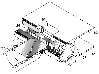
The blades are pivotally attached to the hub by resilient mounts 25 located at
the
intersection of the tube end and the blade root member. The resilient mounts
are typically
bushings having a rigid metal core 26 coaxial with a metal sleeve 27, A
cylindrical vibration-
absorbing and resilient elastomer layer 28 is between the metal core and the
sleeve. The
cylindrical elastomer layer in the resilient mounts allows a litxiited amount
of rotation about an
axis 1 I extending through the center of the resilient mounts, yet is stiff
enough to support the
blades against gravity with only a slight angle of declination. As a result.
when the fan is not
running. the blades generally ''droop" down out of a plane normal to the axis
13 of the fan due
to the weight of the blades. In operation. centrifugal force causes the blades
to rise to their
working position in a manner similar to the blades of a helicopter. The
resilient mounts are
arranged firmly to resist bending moments about the axis of the fan so as to
support the driving
torque and any oscillating forces due to the drive or to cross-winds.
There are at Ieast two major advantages to such a design. First, compared to
fans with
rigidly mounted blades, only 114 to 1/2 of the stresses caused by the air load
need to be supported
by the blade root or are transmitted to the hub and drive. substantially
increasing the life of the
fan blades and the driving mechanism. Second. the resultixsg fan is ideally
suited for operation
by variable speed motors since resonant frequencies are eliminated and there
are no critical
speeds to be avoided. The fact that the blades are effectively hinged at the
mount relieves a
significant amount of the verrical banding moment transmitted to the hub.
_; _
CA 02294183 1999-12-21
WO 99/60276 PCT/US99/10334
1 A typical blade in such a large fan is fabricated from sheet aluminum alloy,
with an
exemplary wall thickness of about 1.5 millimeters. The sheet aluminum is bent
into an airfoil
shape with a generous curvature at a leading edge 24 of the blade. The edges
of the sheet are
brought together along a trailing edge of the blade, such that the resulting
airfoil blade has a
convex lower face 15 and a substantially flat upper face 17. The trailing edge
19 of the flat upper
face is bent at an angle to mate with the trailing edge of the cambered lower
face, where the
edges are fastened together by a line of rivets 21. The balance of the upper
face adjacent to the
hub is substantially flat. A flat face is employed at the inner end of the
blade where it attaches
to the hub to resist bending moment in the circumferential direction. Further
from the inner end
of the blade, curvature (either convex or concave) may be present on both the
upper and lower
faces of the blade. If desired in longer blades where greater stiffness is
needed, a spar or other
stiffening device may also be secured within the blade, or the blade may be
foam filled.
In a presently preferred embodiment, a buttress thread 30, which has been
modified to
exhibit high fatigue strength, is utilized to couple the inner end 32 of the
hub strut to the hub.
Referring now to FIG. 4, the thread is a modified American Standard buttress
profile thread, with
a 7° load flank angle and a 45 ° relief flank angle and a 1.5
millimeter pitch. The standard
buttress thread has been modified, however, by rounding off both the root 34
and the crest 36 of
each thread. In an exemplary embodiment the root has a radius of about 230
micrometers and
the crest has a radius of about 203 micrometers. By modifying the threads in
this manner, the
resulting buttress thread continues to impart relatively high levels of axial
force, without
imparting any appreciable radial force to the components, while gaining
appreciably in fatigue
strength. Additionally, the resulting buttress thread produces a strong lock
between the
respective components, which prevents chafing and increases overall fatigue
life. The buttress
threads are aligned oppositely in the hub strut so that the 7 ° load
flank of each thread supports
the force along the thread axis.
The inner end of each hub strut and a corresponding section of the rotatable
hub are
internally threaded with the modified buttress thread 30 described above. The
inner end of each
hub strut is preferably provided with a gradual radius 77 (FIG. 13) adjacent
the threads to relieve
stress on the threads 30. A stud or coupling member 38 (FIGS. SA and SB) is
provided at the
inner end of each hub strut for coupling the hub strut to the hub. The
coupling member is also
externally threaded with the modified buttress thread 30 described above.
Preferably, the internal thread on the inner end of the hub strut is opposite
the internal
thread on the corresponding section of the rotatable hub (i.e. one is a left-
handed thread while
the other is a right-handed thread). Therefore, one end of the coupling member
is externally
threaded with a left-handed thread, and the other end of the coupling member
is externally
threaded with a right-handed thread. As a result of this design, the coupling
of the hub strut to
the rotatable hub may be tightened by turning the coupling member in one
direction. To
facilitate coupling the coupling member to the hub and hub strut. a hexagonal
axial bore 31 (FIG.
-4-
CA 02294183 1999-12-21
WO 99/60276 PCT/US99/10334
1 SB) extends into the member.
The coupling member includes a central groove 33 between the right-hand
threads and
the left-hand threads, which provides some thread relief so the opposing
threads do not run
directly into one another. In the embodiment illustrated in FIG. SA, the
thread length on one end
35 of the coupling member is shorter than the thread length on the other end
37 of the coupling
member. Preferably, the end of the coupling member with the shorter thread
length is coupled
to the hub.
Additionally, a pair of curved recesses 39 are provided in the coupling member
to act as
stress distributors. The reduced and changing thickness of the stud adjacent
the beginning of the
thread permits deformation of the stud and thread upon tightening. The
tapering wall thickness
distributes a portion of the stress more or less uniformly on the threads.
This reduces the stress
level on the first few turns of the thread and significantly enhances fatigue
resistance at the hub
to strut connection.
In a presently preferred embodiment, an Acme thread 41, which has been
modified to
minimize chafing and maximize fatigue life, is utilized to couple the tube end
22 to the outer end
of the hub stmt. Referring now to FIG. 6, the thread is a modified stub Acme
profile thread, with
a 29 ° thread angle and a 1.5 millimeter pitch. The standard Acme
thread has been modified,
however, by rounding off both the root 40 and the crest 42 of each thread. For
example, in an
exemplary embodiment illustrated in FIG. 6, a radius as high as 0.6 mm is
utilized at the center
of the root of each of the male and female threads.
The outer end 20 of each hub strut is internally threaded with the modified
stub Acme
thread 41 described above. The outer end of each hub strut is preferably
provided with a gradual
radius 79 (FIG. 14) adjacent the threads to relieve stress on the threads 41.
One end 46 of each
corresponding tube end is externally threaded with the modified stub Acme
thread 41 described
above.
A longitudinal slot 48 and corresponding clamping means 50 are provided on the
outer
end of each hub strut. Once the tube end is threaded into the outer end of the
hub strut, the
clamping means are tightened to lock the threads 41 together more tightly,
which minimizes
chafing. In the embodiment illustrated in FIG. 2, the clamping means includes
a pair of clamping
members 52 on opposite sides of the axial slot. A fastener such as a bolt 54
extends between the
clamping members transverse to the axis of the hub strut for tightening the
two clamping
members toward each other. Either a nut may be used (as in FIG. 2) or one
clamping member
may be threaded to receive a threaded end of the bolt. A longitudinal dovetail-
like groove 56
(hereinafter referred to as a dovetail groove f runs along each side of the
axial slot for engaging
a complementary face on the lower surface of each clamping member to secure
the clamping
members to the hub strut. There is a shallow rounded groove 55 extending
generally tangential
to the wall of the hub strut (FIG. 8). An edge of the bolt between the
clamping members lies in
the groove, preventing the clamping assembly from flying off the end of the
hub strut, if not
CA 02294183 1999-12-21
WO 99/60276 PCTNS99/10334
1 properly tightened.
The other end 58 of each tube end is coupled to a corresponding blade root
member. Each
blade root member includes a generally cylindrical base section 60, an upper
surface or ear 62
extending laterally outwardly from the base section ( longitudinally relative
to the blade length},
and a lower surface or ear 64, spaced apart from the upper surface. extending
laterally outwardly
from the base section. The upper and lower surfaces of the blade root member
are attached, such
as by riveting, to the upper and lower faces, respectively, of the
corresponding side of the blade
skin of the blade. An exemplary pattern of rivets 61 between the inner end of
the blade and the
blade root member is illustrated in FIG. 11. Such a pattern is used to
distribute stresses among
the rivets and in the blade skin adjacent to the rivets in order to improve
fatigue resistance.
In a presently preferred embodiment, a pair of notches 66 are formed in
opposite sides 68,
70 of the lower surface of the blade root member to allow the lower surface of
the blade root
member to be angled as illustrated in FIG. 8 to conform approximately to the
convex lower face
of the blade skin. Since the notches 66 act as stress risers in the lower
surface of the blade root
member, and thus could adversely affect fatigue strength, they are preferably
rounded at the root
to minimize the stress rise at the bottom of the notches. This shaping, in
combination with the
design of the blade skin, allows the present invention to take advantage of
the flexibility of the
convex lower face of the blade skin and the rigidity of the flat upper face of
the blade skin such
that most of the bending moment about the fan shaft is supported on the
relatively rigid upper
face.
A pair of transversely extending cylindrical bores 72 are provided on opposite
sides 74,
76 of the base section of the blade root member, one bore on each side of the
base section for
receiving a resilient mount, which may be press fit into the corresponding
cylindrical bore. A
wide notch 78 is provided in the center 80 of the base section, between the
cylindrical bores 72,
for receiving the end 58 of the tube end.
A blade root bolt 82 is used to firmly couple the blade root member to the
tube end. The
blade root bolt extends transversely through the blade root member, from one
resilient mount,
through a bore 84 provided in the end 58 of the tube end. to the other
resilient mount carried by
the blade root member. To receive the blade root bolt, both of the resilient
mounts are provided
with axially extending bores, one of the bores 86 (FIG. 9) being threaded to
receive a threaded
end of the blade root bolt, and the other bore 88 (FIG. 10) designed to
receive the blade root bolt
head.
The metal core or center of each resilient mount has a pair of flat tapered
surfaces 90 on
its interior end that engage a matching profile on the sides 91 of the end of
tube end. The blade
root bolt clamps the resilient mounts against the tube end when the blade root
bolt is tightened
so as to prevent any appreciable movement between the resilient mounts and
tube end. In the
exemplary embodiment illustrated in FIGS. 9 and 10, the interior end of each
of the resilient
mounts is beveled at an angle of about twenty-six decrees on each taper.
Refernng again to FIG.
-b-
CA 02294183 1999-12-21
WO 99/60276 PCT/US99/10334
1 7, the sides 92,94 of the tube end are tapered at a complementary angle in
such a manner to
tightly receive the beveled ends of the resilient mounts when the blade root
bolt is tightened. As
a result, the flat tapered surfaces 90 of the resilient mounts engage the
matching beveled surfaces
91 of each side of the tube end (FIG. 12). This provides a positive connection
between the end
of the blade and the hub, as contrasted with the friction connection provided
by the prior clevis
mounting.
The positive connection between the blade root member and the tube end may be
provided
by other complementary surfaces. such as, for example, shallow grooves and
ridges corrugating
the opposed surfaces. A pair of complementary cylindrical surfaces may also be
sufficient for
preventing rotation of the resiliently mounted cores relative to the tube end.
By providing a
positive connection between the blade root member and the tube end. drooping
of the blade is
limited and one can avoid use of mechanical stops to limit the blades downward
and sometimes
upward travel. This is beneficial for avoiding impact forces and the resulting
high stresses when
the blade hits the stops, as during starting, stopping and in high cross-
winds.
In the illustrated embodiment, the resilient mounts each comprise a core and
sleeve with
a layer of elastomer between the core and sleeve. These are press fit into the
blade root member.
Alternatively, one may position a core of a resilient mount within a
cylindrical end of the blade
root member and cast the elastomer in between the core and blade root member,
thereby
eliminating the sleeve.
Blades are mounted on a fan as follows: The hub struts are connected to the
central hub
by starting a thread of the stud into the hub then into the strut. By
selectively rotating the strut
and stud, the joint between the hub and strut can be positioned adjacent to
the thread relief
groove in the stud. The stud is then rotated via the hexagonal bore to draw
the strut and hub
tightly together. Finally, the tube is rotated about 60° to the desired
tightened torque. The tube
end is threaded into the outer end of a hub strut to approximately its final
position.
Meanwhile, a blade skin has been riveted to the ears on the blade root member
and
resilient mounts are press fit into the two opposite sides of the blade root
member. Holes or
notches are provided in the outer end of each of the resilient mounts so the
profiled ends of the
mounts are properly oriented relative to the blade length.
It might be noted that after the elastomeric layer has been applied between
the core and
sleeve of a resilient mount, it is desirable to swage the sleeve after the
elastomer has cured to
place the elastomer in compression. If one uses an embodiment where the sleeve
is eliminated
and the elastomer is directly between a core and the blade root member. it may
be desirable to
swage the inner care outwardly after the elastomer has cured to add
compression. In such case,
the resiliently mounted cores may be clamped against a tube end by a nut and
bolt instead of a
bolt threaded into one of the cores.
The blade mot member is slid over the tube end so as to straddle the outer end
of the tube
end, with the tapered ends of the cores of the resilient mounts aligned with
the tapered profiles
CA 02294183 1999-12-21
WO 99/60276 PCT/US99/10334
1 on the tube end. The blade mot bolt is introduced and tightened to securely
clamp the blade root
member to the tube end. The tube end can then be rotated in the hub strut to
adjust the blade
length to clear the shroud of the fan, and finally when the length is proper,
adjust the angle of
attack of the blade for optimum e~ciency. When the angle of attack is properly
set, the clamp
on the hub strut is tightened and installation can proceed to the next blade
of the fan. A sheet
metal aerodynamic hub shroud (not shown) is mounted on the hub or hub struts
as an air seal at
the center of the fan.
The adjustment of the blade position via the threaded tube end allows each
blade to be
adjusted about t19 mm, or about X38 mm from the nominal diameter of the fan,
for clearing a
shroud a desired distance. Each blade length can be adjusted to an accuracy of
one half pitch of
the thread.
The teachings of the present invention with respect to fan blade mounting
result in a fan
that is stronger and more fatigue resistant than prior art fans. For example,
each of the blades
on a large air-moving fan constructed according to the present invention has
increased resistance
to fatigue failure. and blades with a chord length increased about 40% at the
root and tip as
compared with blades mounted with the prior clevis arrangement. This increase
in effective area
of the blades means. for example, that a fan can be made with 10 blades having
the same
aerodynamic capability as a prior fan with 14 blades. Although the cost per
blade is increased,
the total cost of the fan is significantly reduced.
The improved means for attaching the blades to the hub allows static and
oscillating
torques about the axis of rotation of about 3.2 times those of the prior
design. Also, the new
mount and tube end design supports the blade against gravity, unlike the prior
design which
required a metal "rest stop" to support longer blades when the fan was
stopped. Thus, even with
40% larger blade area, the new design has about 3.2/I .4 = 2.28 times as much
torque capacity
per unit blade area. This allows the operation of fans having an area of 2.28
times that of prior
fans for the same air pressures and/or allows fans to operate under
equivalently more stressful
conditions.
35
_g_