Note: Descriptions are shown in the official language in which they were submitted.
CA 02294284 1999-12-22
WO 99/00856 PCT/US98/13527
SNAP-THROUGH GASKET FOR GALVANIC CELLS
Field of the Invention
The invention relates to a compressive preloaded
snap-through gasket seal for galvanic cells and more
particularly to a seal means for preventing premature
release of gas pressure from inside the cells.
BACKGROUND OF THE INVENTION
Galvanic cells may generate large quantities of
gas under certain conditions during use. Since these
cells are required to be tightly sealed at all times in
order to prevent loss of electrolyte by leakage, high
internal gas pressures may develop. Such pressures may
cause leakage, bulging or possible explosion of the
cell if not properly vented. If a vent valve is
employed, it may be resealable in order to avoid drying
out of the electrolyte over the life of the cell and to
prevent ingress of oxygen from the atmosphere which can
cause wasteful corrosion of the anode.
In the past several different types of resealable
pressure relief vent valves have been used for
releasing high internal gas pressures from inside a
sealed galvanic cell. One type of valve that has been
commonly used consists basically of a valve member,
such as a flat rubber gasket, which is biased into a
sealing position over a vent orifice by means of a
resilient member, such as a helical spring. The
resilient member or spring is designed to yield at a
certain predetermined internal gas pressure so as to
momentarily relieve the seal and allow the gas to
escape through the vent orifice.
CA 02294284 1999-12-22
WO 99/00856 PCT/US98/13527
- 2 -
Another type of resealable vent is disclosed in
U.S. Patent No. 3,451,690 to Richman issued on December
10, 1968. In this vent, a flat elastomeric seal gasket
overlies the vent opening and is retained in place by a
resilient terminal cap on the top of the cell. This
vent operates in basically the same manner as the vents
previously described.
In U.S. Patent No. 3,664,878 to Amthor issued on
May 23, 1972, a resealable vent is disclosed which
comprises a resilient deformable ball of elastomeric
material positioned to overlie a vent orifice provided
within the cell's container. A retainer means is
positioned over the resilient ball for maintaining the
ball in place over the vent orifice and in contact
with a valve seat provided around the peripheral edge
portions of the vent orifice and for compressing and
deforming the resilient ball into a flattened
configuration forming a normally fluid-tight seal
between the flattened ball and the valve seat. The
resilient ball is capable of undergoing further
temporary deformation upon the buildup of a
predetermined high internal gas pressure inside the
container so as to momentarily break the seal and
allow gas to escape through the vent orifice.
Alternates to high pressure resealable vent means
are fail safe venting systems as illustrated in U.S.
Patent Nos. 3,218,197 and 3,314,824. Specifically in
the '197 patent a venting means is disclosed in which
the seal gasket has a thin section that will rupture
or "blow-out" at a predetermined high pressure buildup
within the cell. The difficulty with this type of
venting means is that for small diameter cells it is
difficult to obtain consistency in the thickness of
CA 02294284 1999-12-22
WO 99/00856 PCT/US98/13527
- 3 -
the "blow-out" section of the gasket using
conventional manufacturing techniques. In the '824
patent a puncture-type safety seal is disclosed which
comprises a spring washer positioned within the cell's
seal assembly and a radially acting toothed puncture
washer. The teeth of the washer slide relative to the
spring washer when the spring washer is subjected to
internal pressure so that at a predetermined gas
pressure buildup, the teeth of the washer will
puncture the seal's gasket thereby providing a vent
passage. This type of venting means requires several
component parts, is rather expensive to make and
assemble, and is not suitable for small diameter
cells.
U.S. Patent No. 4,079,172 discloses sealed
galvanic dry cells having at least one gas venting
passage disposed at the interface of the top surface
of the cover and then curled over the rim of the
container. The passage is defined as being a recess in
the cover disposed below the curled over rim and/or a
notch in a portion of the curled over rim.
U.S. Patent No. 5,227,261 relates to
electrochemical cells which are comprised of a seal
member that has a centrally located cylindrical hub
joining a base, which base has a veritable diaphragm
portion and a nonventable diaphragm portion, which hub
has an end extending above the base and an end
extending below the base, into which a current
collector is inserted in an interference fit with the
end extending above the base, which veritable diaphragm
portion joins the hub at an interface forming an arc of
between about 135 degrees and 250 degrees, and which
interface is the thinnest portion of the base.
CA 02294284 1999-12-22
WO 99/00856 PCT/US98/13527
- 4 -
U.S. Patent No. 4,255,499 relates to a galvanic
cell in which a first arc portion between about 150°
and 190° of the top peripheral edge of the container is
turned or curled over the container's closure means so
that when a predetermined high pressure build-up
develops in the cell, the pressure will cause the
closure means to tip or tilt about the diametral axis
formed between the first arc portion and the remaining
second arc portion so as to produce a vent passage at
the interface of the container and the closure means
proximal the remaining second arc portion of the top
peripheral edge of the container.
As discussed above, resealable, high pressure
relief vent valves are generally bulky and/or difficult
to incorporate into a cell assembly, bulky type of
blow-out safety vents are not suitable for small cell
applications, while low pressure vent means for some
cell systems may not adequately and sufficiently
prevent loss of electrolyte through leakage or prevent
ingress of oxygen from the atmosphere which could cause
wasteful corrosion of the anode.
It is, therefore, an important object of this
invention to provide a compact and economical pressure
vent for use in a galvanic cell that will effectively
occupy minimum volume so that maximum volume of the
cell can be used for the active components of the cell.
Still another object of this invention is to
provide a predetermined pressure vent using a
snap-through gasket for galvanic cells which is easy to
produce and inexpensive to manufacture.
Another object of the present invention is to
provide a vent which prevents premature release of gas
pressure from within a galvanic cell.
CA 02294284 1999-12-22
WO 99/00856 PCT/US98/13527
- 5 -
The foregoing and additional objects will become
more fully apparent from the following description and
the accompanying drawings.
SUN~ARY OF THE INVENTION
The invention relates to an electrochemical cell
comprising an anode electrode, a cathode electrode and
an electrolyte contained in a container, said container
having an open end and a closed end and wherein the
open end of the container is sealed with a gasket, said
gasket comprising a base member having an upstanding
peripheral wall and a centrally located upstanding wall
forming a hub defining an openings said base member
having a first segment extending radially inward from
the upstanding peripheral wall to a second segment
disposed substantially in parallel to the upstanding
wall of the hub, said second segment extending to a
third segment disposed between the second segment and
the upstanding wall of the hub, said third segment
having a bowed surface facing the closed end of the
container and having a notch, preferably on the inner
surface of the third segment, and the bowed third
segment provided with a compressive preload force in at
least a portion of the area of the third segment,
preferably between 10° to 360°, adjacent to the
upstanding wall of the hub that will delay the onset of
tensile stresses at the area adjacent the hub caused by
any pressure buildup of gasses produced in the cell, so
that premature venting of the cell can be prevented.
Preferably the cross-sectional area of the third
segment adjacent the upstanding wall at the hub should
have a thickness of between 1/8 and 3/4 of the
thickness of the third segment between the second
CA 02294284 1999-12-22
WO 99/00856 PCT/US98/13527
- 6 -
segment and the notch. The reduced area adjacent to the
hub of the gasket will be in compression and therefore,
absorb the initial low pressure of gas buildup within a
cell, so that premature venting of the cell can be
prevented. The thickness of the cross-sectional area
adjacent to the first segment and the second segment
has a thickness preferably between about 1~ and 2~
times the cross-sectional thickness of the first
segment. The cooperation of the first segment and the
second segment provides a hinge type means so that
radial forces applied to the peripheral wall of the
gasket will be transferred via the first segment to the
second segment, which in turn will cause transfer of
force to the third segment. This force to the third
segment will cause the third segment to bow inwardly
due to the more flexible characteristics of the third
segment provided by the notch in the internal surface
of the third section. The notch or groove is provided
to make the third section more flexible and will bow
inwardly during the redrawing and/or crimping of the
container onto the gasket. The bowing of the third
section will provide a compressive force on the area of
the third section adjacent to the wall of the hub.
After the final assembly of the cell, the third segment
of the gasket will be in a compressive preloading in
the vent corner or area adjacent to the hub that will
delay the onset of tensile stresses upon the gasket.
The gasket will be able to tolerate a predetermined
pressure buildup within the cell to prevent premature
venting but upon a high pressure buildup within the
cell, the third section of the gasket is designed to
provide a snap-through feature so that the third
segment will snap from a convex bow design facing the
CA 02294284 1999-12-22
WO 99/00856 PCT/US98/13527
closed end of the container to a convex bow design
facing the open end of the container. The novel
snap-through feature of the gasket provides a
construction that would occupy minimum internal volume
due to the minimum height of the gasket so that maximum
internal volume can be used for the active components
of the cell. Thus, with the novel construction of the
gasket of this invention, the cell pressure on the
gasket can be increased without the venting of the
cell. This feature can be accomplished with a
combination of compressive preloading and the creation
of the snap-through behavior of the third segment of
this gasket.
The gasket of this invention is constructed with
several segments that cooperate during the assembly of
the cell to place a compressive preload in a segment of
the gasket that will delay the onset of tensile
stresses in the vent area of the gasket and therefore
prevent premature venting of the cell. It has been
found that using the novel gasket of this invention,
the onset of tensile stresses can be prevented, if
desired, up to about 200 psi internal pressure for
C-size cells. Cell closing may increase compression in
the reduced area of the gasket adjacent the hub.
The purpose of compressive preloading is to
eliminate tensile stress as at the inside angle formed
by the junction of the third segment and the wall of
the hub under normal operating pressures. In the
assembled cell the area of the gasket adjacent to the
hub is in compression. As the internal pressure is
increased, the inside angle, defined as the angle
between the area adjacent the hub and the wall of the
- hub, passes through 90 degrees.
CA 02294284 1999-12-22
WO 99/00856 PCT/US98/13527
_ g _
The thickness of the reduced area in the third
segment is preferably between 1/8 to 3/4 times the
cross-sectional average thickness of the third segment
disposed between the notch and the second segment.
The upstanding wall of the hub can be provided
with a flange to accommodate the centrally disposed
edge of the cover (inner cover) of a cell. Also the
upstanding peripheral wall of the gasket could be
provided with a flange to accommodate the peripheral
edge of the inner cover. If desired, a rib or rim could
be disposed on the upstanding peripheral wall of the
gasket to secure the peripheral edge of the inner cover
onto the first and second segments of the gasket.
Preferably, an inner cover having an opening to
accommodate the hub is disposed within the peripheral
wall and is secured between the peripheral wall and the
hub of the seal assembly.
Preferably, the gasket in conjunction with the
cover are secured to the container by redrawing and/or
crimping the rim of the container against the gasket
and the cover. In this embodiment, the gasket which is
generally a nonconductive synthetic material, will act
as an insulator as well as a barrier to air and
moisture and will be strong enough to maintain its
sealing after it has been physically abused such as by
dropping or exposure to vibration and/or subject to
extreme variations in temperature and/or humidity
and/or abuse charging.
Cylindrical alkaline cells are generally comprised
of a containment means and the components located
within the containment means. The containment means
comprises an elongated container, that is open on one
end, and a vent assembly. The assembly is made up of a
CA 02294284 1999-12-22
WO 99/00856 PCT/US98/13527
_ g _
terminal cover plate; an elastomeric gasket; and an
inner cover and current collector. The members of the
vent assembly are inserted into the open end of the
container thereby sealing the container. The rim
portion of the container is then redrawn and/or crimped
inwardly to form a seal.
The sealing gasket of this invention comprises a
material selected with consideration given to its
stability in the presence of the electrolyte, its
resiliency, and its resistance to cold flow. Suitable
polymeric materials are selected from the group
consisting of nylon, polytetrafluoroethylene,
fluorinated etheylene-propylene,
chlorotrifluoroethylene, perfluoro-alkoxy polymer,
polyvinyls, polyethylene, polypropylene, polystyrene
and the like. Other suitable materials would be
recognizable by one skilled in the art. In some
applications, additional precautions can be used in
conjunction with the gasket of this invention to
provide a more effective seal, such as coating the
flange of the gasket surfaces with an adhesive agent
such as a fatty polyamide resin or asphalt. The
sealing gasket of this invention is suitable for
production techniques such as injection molding. The
configuration of the surfaces of the gasket flanges is
well suited for ease of removal from dies, punches and
the like. Preferably the gasket would be nylon. The
terminal cover should be made of a conductive material
that will not corrode or otherwise deteriorate when in
contact with the materials of the cell. The container
for the cell could be made of stainless steel, iron,
nickel, nickel-plated steel, or some other conductive
material.
CA 02294284 1999-12-22
WO 99/00856 PCT/US98/13527
- 10 -
The invention also relates to a method for making
a galvanic dry cell having a pressure vent closure with
a safety feature that prevents premature venting of a
cell which comprises the steps:
(a) placing within a conductive container a
separator, an anode, a cathode, and an electrolyte;
(b) preparing a gasket comprising a base member
having an upstanding peripheral wall and a centrally
located upstanding wall forming a hub defining an
opening, said base member having a first segment
extending radially inward from the upstanding
peripheral wall to a second segment disposed
substantially parallel to the upstanding wall of the
hub, said second segment extending to a third segment
disposed between the second segment and the upstanding
wall of the hub, said third segment being bowed so
that it faces the closed end of the container and
having a notch, and the bowed third segment being
provided with a compressive preload force in the area
of the third segment adjacent to the upstanding wall
of the hub that will delay the onset of tensile
stresses at the area adjacent the hub caused by any
pressure buildup of gasses produced in the cell, so
that premature venting of the cell can be prevented;
(c) assembling an inner cover, the gasket and a
current collector into the container; and
(d) reducing the top edge portion of the
container over the peripheral wall of the gasket onto
the inner cover to provide a sealed cell, and wherein
said area adjacent the hub is in a compressive
preloadinq stress state. As used herein, the term
reducing the top edge portion of the container shall
mean a redrawing step, a crimping step or any other
CA 02294284 1999-12-22
WO 99/OU856 PCT/US98/13527
- 11 -
step that will impart a compressive force on the
reduced thickness of the gasket.
The notch in the third segment is preferably
located between 1/4 and 3/4 the length of the third
segment and more preferably between 1/3 to 2/3 of the
length of the third segment.
Description of the Drawings
The present invention will become more apparent
from the following description thereof when considered
together with the accompanying drawings which are set
forth as being exemplary of the embodiments of the
present invention and is not intended in any way to be
limitative thereof and wherein:
Fig. 1 is a partial cross-section of a gasket for
use in a cell.
Fig. 2 is a sectional elevation of the gasket
means of Fig. 1 shown after assembled in a galvanic
cell.
Fig. 3 is a partial cross-section of a deformed
gasket after being exposed to high internal pressure.
Referring to Figs. 1-3, there is shown gasket 1
comprising a base member 2 with an upstanding
peripheral wall 4 and an upstanding centrally located
cylindrical hub 6. Disposed in the base member 2
between the upstanding peripheral wall 4 and hub 6 is
a first segment 8, a second segment 10, and third
segment 12. The angle A formed by first segment 8 and
second segment 10 is shown as about 70°. A flange 38
is shown and is designed to support inner cover 19, as
shown on Figure 2. As shown in Figure 1, the thickness
of section 11 is about 1'-~ times the thickness of the
first segment 8. Figure 2 shows the gasket of Figure 1
CA 02294284 1999-12-22
WO 99/00856 PCT/US98113527
- 12 -
assembled in a galvanic cell 20. The inside angle B as
shown in Fig. 1 is about 80° formed between the
reduced area segment 18 and the wall 7 of hub 6. A
notch 15 is shown in the third segment 12 of the
gasket 1. This notch 15 is provided to make the third
section 12 more flexible and will bow inwardly during
the redrawing or crimping of the container onto the
gasket. The bowing of the third section 12 will
provide a compressive force on the reduced thickness
portion 18 of the third section 12 adjacent to the
hub.
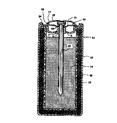
Fig. 2 shows an assembled alkaline manganese
dioxide-zinc cell 20 comprising container 22 having
disposed therein an anode mix 24 and cathode 26
separated by a separator 28. The anode mix 24 could
comprise particulated zinc with a gelling agent and an
electrolyte, such as aqueous potassium hydroxide. The
cathode could comprise manganese dioxide and a
conductive material, such as graphite. As shown in Fig.
2, the gasket 1 of Fig. 1 is positioned within the open
end of the container 22 where the gasket 1 rests on the
cathode 26. If desired, a layer of sealant may be
disposed at the interface of the seal and the
container. Upon inserting gasket 1, cover 19 and
current collector 30 in container 22, current collector
made good electrical contact in the anode mix 24.
Once the gasket 1 is seated within container 22, and
the cover 19 is seated within gasket 1, a terminal
cover 32 is disposed over the current collector 30, and
30 then the annular edge segment 34 of container 22 is
radially compressed and crimped against the gasket 1,
cover 19, cover 32, thereby radially sealing the gasket
1 to the opening of the container 22.
CA 02294284 1999-12-22
WO 99/00856 PCT/US98/13527
- 13 -
The inner cover 19 is designed to seat within seal
gasket 1 on flange 38 of wall 7 of hub 6. An opening 35
is disposed in inner cover 19 and an opening 37 is
disposed in terminal cover 32 to permit the internal
pressure to vent,
As shown in Fig. 2, the reduced area of the third
segment 12 of the gasket 1 is put under a compressing
stress during the redrawing and!or crimping step. This
preloading stress on the gasket delays the onset of
tensile stresses in the reduced area to prevent
premature venting of cell. Fig. 3 shows the gasket 1 of
Figs. 1 and 2 after being subjected to a high pressure
force from within the cell that invert the third
segment 12 outwardly and places the reduced area 18 in
tension. If the pressure buildup is severe, the gasket
will snap through to permit venting.
It is to be understood that other modifications
and changes to the preferred embodiment of the
invention herein shown and described can also be made
without departing from the spirit and scope of the
invention.