Language selection

Search

Patent 2294302 Summary

Third-party information liability

Some of the information on this Web page has been provided by external sources. The Government of Canada is not responsible for the accuracy, reliability or currency of the information supplied by external sources. Users wishing to rely upon this information should consult directly with the source of the information. Content provided by external sources is not subject to official languages, privacy and accessibility requirements.

Claims and Abstract availability

Any discrepancies in the text and image of the Claims and Abstract are due to differing posting times. Text of the Claims and Abstract are posted:

  • At the time the application is open to public inspection;
  • At the time of issue of the patent (grant).
(12) Patent Application: (11) CA 2294302
(54) English Title: REAR SUPPORT FOR A HEAVY GOODS VEHICLE WITH AN AUTOMATIC LOADING DEVICE
(54) French Title: SUPPORT DE PARTIE ARRIERE POUR VEHICULE POUR CHARGES LOURDES POURVU D'UN DISPOSITIF DE CHARGEMENT AUTOMATIQUE
Status: Deemed Abandoned and Beyond the Period of Reinstatement - Pending Response to Notice of Disregarded Communication
Bibliographic Data
(51) International Patent Classification (IPC):
  • B60S 09/12 (2006.01)
  • B60P 01/48 (2006.01)
(72) Inventors :
  • HEBER, ERICH (Germany)
(73) Owners :
  • MASCHINENBAU KIROW LEIPZIG RAIL & PORT AG
(71) Applicants :
  • MASCHINENBAU KIROW LEIPZIG RAIL & PORT AG (Germany)
(74) Agent: RICHES, MCKENZIE & HERBERT LLP
(74) Associate agent:
(45) Issued:
(86) PCT Filing Date: 1998-06-15
(87) Open to Public Inspection: 1998-12-23
Availability of licence: N/A
Dedicated to the Public: N/A
(25) Language of filing: English

Patent Cooperation Treaty (PCT): Yes
(86) PCT Filing Number: PCT/EP1998/003578
(87) International Publication Number: EP1998003578
(85) National Entry: 1999-12-14

(30) Application Priority Data:
Application No. Country/Territory Date
297 10 956.1 (Germany) 1997-06-15

Abstracts

English Abstract


The invention relates to a heavy goods vehicle with an automatic loading
device for heavy loads, which is arranged on the frame of said vehicle, whose
end protrudes above a rear wheel and which is provided with a support device
underneath to support the rear part of the vehicle on a hydraulically
extendible base plate (20). The invention is characterized in that the support
device has two stable casings (4, 5). One external casing (4) is built into
the frame of the motor vehicle, and an inner closed casing (5) surrounds a
hydraulic cylinder with which the inner casing can be moved in the direction
of the axis (A) of the casing.


French Abstract

L'invention concerne un véhicule pour charges lourdes comprenant un dispositif de chargement automatique pour charges lourdes, disposé sur un châssis de véhicule, dont l'extrémité dépasse au-dessus d'une roue arrière et présente, sur le dessous, un dispositif de support servant au support de la partie arrière sur une plaque de fond (20) pouvant être sortie hydrauliquement. Le véhicule selon l'invention se caractérise en ce que le dispositif de support comporte deux carters stables (4, 5), à savoir un carter extérieur (4), qui est intégré au châssis du véhicule, et un carter intérieur (5), fermé, qui entoure un vérin hydraulique à l'aide duquel ce carter intérieur (5) peut être déplacé dans le sens de son axe (A).

Claims

Note: Claims are shown in the official language in which they were submitted.

-5-
Claims
1. Heavy-duty vehicle with an automatic loading device (22) for heavy loads
which is arranged on a vehicle frame whose end (13) projects out over a rear
wheel
(23) and has, at its underside, a supporting device (2, 2a) with two stable
housings (4,
5) for supporting the rear on a bottom plate (20) which can be moved out
hydraulically,
characterized in that an outer housing is integrated in the vehicle frame (13)
and an
inner, closed housing (5) encloses a hydraulic cylinder (7) by means of which
the inner
housing is movable in the direction of the housing axis (A).
2. Heavy-duty vehicle according to claim 1, characterized in that the inner
housing (5) is closed at the bottom by means of a welded-on bottom plate (20).
3. Heavy-duty vehicle according to claim 1 or 2, characterized in that the
bottom plate (20) has front and rear skids (16) at least in the longitudinal
direction of the
vehicle.
4. Heavy-duty vehicle according to one of the preceding claims,
characterized in that the piston rod {9) is supported in the inner housing (5)
so as to be
swivelably movable by means of an integrated articulated bearing (10).
5. Heavy-duty vehicle according to one of the preceding claims,
characterized in that the inner housing (5) is guided in the outer housing (4)
by sliding
plates (6).
6. Heavy-duty vehicle according to one of the preceding claims,
characterized in that the cylinder (7) is held inside the vehicle frame (13)
by pins (8) in
the outer housing (4).

Description

Note: Descriptions are shown in the official language in which they were submitted.


CA 02294302 1999-12-14
REAR SUPPORT FOR A HEAVY GOODS VEHICLE WITH AN AUTOMATIC
LOADING DEVICE
Description
The invention is directed to a heavy-duty vehicle with an automatic loading
device for heavy loads which is arranged on a vehicle frame whose end projects
out
over a rear wheel and has, at its underside, a supporting device for
supporting the rear
on a bottom plate which can travel out hydraulically.
DE 36 05 665 C2 discloses a vehicle of the generic type which is provided for
lifting, transporting and tipping a slag vessel or the like provided with side
trunnions and
has a swiveling frame at the rear, by which the slag vessel can be raised or
lowered in a
swiveling manner on the vehicle over the rear and which has a hydraulic
actuating
member behind the rear wheel below the frame for a jib base which can be
supported
on the ground.
These two rear supporting devices under both lateral ends of the vehicle are
required to ensure the stability of the vehicle during the movement of the
heavy load. In
the device of the generic type, the piston rod, when in the moved out state,
is exposed
to the hostile influences in the metallurgical plant, e.g., slag sprays, acid
rain and the
like, and can therefore be severely damaged to the point of blockage. The
bottom plate
is fastened to the piston rod eye so as to be movable in a swiveling manner
and can
therefore tilt.
The construction of the supporting device as a separate structural component
part which is welded on or screwed on to the vehicle frame makes it necessary
in most
cases to switch off the vehicle drive or traveling mechanism of the vehicle
when the
support is moved out in order to prevent damage when advanced unintentionally.
However, as a result of switching off the traveling mechanism, the vehicle can
no longer
be driven away with the support extended, even in emergencies.
Therefore, the invention is based on the problem of providing an improved
supporting device which is adapted to operating conditions.

a
CA 02294302 1999-12-14
-2-
According to the invention, this problem is solved by the features of
protective
claim 1. Further features of the invention are indicated in the subclaims.
The solution according to the invention provides a supporting device which has
two stable housings which are displaceable one inside the other in a
telescoping
manner, wherein the outer housing is integrated directly in the vehicle frame
and
accordingly achieves a very high stability. An inner housing with sliding
plates which
can be arranged on the inner housing as closing plates slides in the outer
housing, but
is constructed as a stable welded construction or is formed of correspondingly
joined
steel plates. The inner housing encloses the hydraulic cylinder which enables
the
movability of the inner housing relative to the outer housing in the
longitudinal direction
of the two housings. A hydraulic cylinder which is protected in this way
remains
operational over a long period and its weakest part, the piston rod, can not
be bent by
external force.
According to a further feature of the invention, the inner housing is closed
at the
bottom by means of a pre-welded bottom plate which is arranged horizontal to
the
undercarriage frame. Therefore, the bottom plate cannot be tilted away by a
small
obstacle such as a rock, but is pressed onto the ground in the predetermined
position.
In the longitudinal direction of the vehicle, the bottom plate has front and
rear
skids, so that the bottom plate and/or the cylinder cannot be torn off when
the vehicle is
advanced unintentionally; rather, the support base can slide over obstacles.
In order to take into account assembly errors or bending loads in the event of
overloading, the piston rod is supported by its eye as a swivelably movable
element in
the inner housing with correspondingly stable eye bolts.
The cylinder itself is held inside the vehicle frame, that is, at the stiffest
part, by a
stable, integrated bolt which can also be constructed as an integrated double-
bolt. The
hydraulic lines can also be reliably guided in the vehicle frame by means of
the
integration of the housing in the vehicle frame.
The invention will be explained more fully with reference to the schematic
drawings.

CA 02294302 1999-12-14
-3-
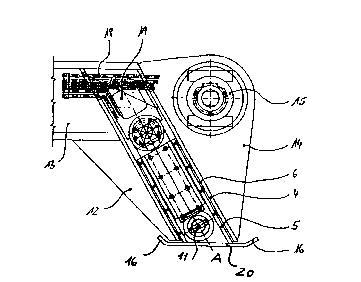
Figure 1 shows a side view with a partial section through the supporting
device;
Figure 2 shows a section along the longitudinal axis of the supporting device
according to Figure 1;
Figure 3 shows a supporting device according to the invention which is
integrated in the vehicle frame of a slag transporter.
Figure 3 shows a heavy-duty vehicle, in this case a slag transporter with a
driving
head 21 and a loading platform 3 on an undercarriage 23 for transporting a
slag vessel
1. The drawing shows the state before the vessel has been loaded by the
vehicle by
means of the automatic loading device 22 in that the swiveling device 22 is
moved
about the swivel joint 15 and can accordingly deposit the vessel 1 behind the
vehicle. A
supporting device is moved out of the driving position 2 into the unloading
position 2a
on the ground before the swiveling movement is initiated, so that the rear of
the vehicle
is supported and the vehicle cannot be tilted about the axis of the wheel 23.
Figure 1 is an enlarged view of the supporting device 2. An outer housing 4 of
steel plates is integrated in the vehicle frame end 13 and, in addition, is
fixedly
connected with a gusset plate 12 and the solid bearing plate 14 for the swivel
bearing
15 of the swiveling device 22. An inner stable housing 5 of steel plate which
is movable
in the direction of the housing axis A by means of a cylinder 7 (Figure 2) is
integrated in
the outer housing 4. The inner housing 5 is closed toward the ground by a
bottom plate
20 which has skids 16 at the front and back. Sliding plates 6 are screwed to
the inner
rectangular housing, so that the inner housing 4 is supported in the outer
housing 5 in a
sliding manner. The hydraulic lines 18 for the cylinder 7 and the automatic
loading
device 22 are guided in the vehicle frame and are accessible through an
inspection flap
19 in the vehicle frame and in the outer housing 4.
Figure 2 shows a section along the longitudinal axis A through the two
housings.
The piston rod 9 has an integrated articulated bearing 10 which is supported
via a pin
AMENDED SHEET

CA 02294302 1999-12-14
-4-
11 in the inner movable box-like housing 5. The cylinder 7 is held at the
vehicle end via
pins 8 in the outer box girder or outer housing 4. The cylinder is protected
in its position
on all sides against environmental influences even when the inner housing is
moved out
into position 2a (Figure 3).

Representative Drawing
A single figure which represents the drawing illustrating the invention.
Administrative Status

2024-08-01:As part of the Next Generation Patents (NGP) transition, the Canadian Patents Database (CPD) now contains a more detailed Event History, which replicates the Event Log of our new back-office solution.

Please note that "Inactive:" events refers to events no longer in use in our new back-office solution.

For a clearer understanding of the status of the application/patent presented on this page, the site Disclaimer , as well as the definitions for Patent , Event History , Maintenance Fee  and Payment History  should be consulted.

Event History

Description Date
Time Limit for Reversal Expired 2004-06-15
Application Not Reinstated by Deadline 2004-06-15
Deemed Abandoned - Failure to Respond to Maintenance Fee Notice 2003-06-16
Inactive: Abandon-RFE+Late fee unpaid-Correspondence sent 2003-06-16
Inactive: Cover page published 2000-02-21
Inactive: IPC assigned 2000-02-17
Inactive: First IPC assigned 2000-02-17
Letter Sent 2000-02-01
Inactive: Notice - National entry - No RFE 2000-02-01
Application Received - PCT 2000-01-28
Application Published (Open to Public Inspection) 1998-12-23

Abandonment History

Abandonment Date Reason Reinstatement Date
2003-06-16

Maintenance Fee

The last payment was received on 2002-05-24

Note : If the full payment has not been received on or before the date indicated, a further fee may be required which may be one of the following

  • the reinstatement fee;
  • the late payment fee; or
  • additional fee to reverse deemed expiry.

Patent fees are adjusted on the 1st of January every year. The amounts above are the current amounts if received by December 31 of the current year.
Please refer to the CIPO Patent Fees web page to see all current fee amounts.

Fee History

Fee Type Anniversary Year Due Date Paid Date
Registration of a document 1999-12-14
Basic national fee - standard 1999-12-14
MF (application, 2nd anniv.) - standard 02 2000-06-15 2000-06-15
MF (application, 3rd anniv.) - standard 03 2001-06-15 2001-05-23
MF (application, 4th anniv.) - standard 04 2002-06-17 2002-05-24
Owners on Record

Note: Records showing the ownership history in alphabetical order.

Current Owners on Record
MASCHINENBAU KIROW LEIPZIG RAIL & PORT AG
Past Owners on Record
ERICH HEBER
Past Owners that do not appear in the "Owners on Record" listing will appear in other documentation within the application.
Documents

To view selected files, please enter reCAPTCHA code :


To view images, click a link in the Document Description column. To download the documents, select one or more checkboxes in the first column and then click the "Download Selected in PDF format (Zip Archive)" or the "Download Selected as Single PDF" button.

List of published and non-published patent-specific documents on the CPD .

If you have any difficulty accessing content, you can call the Client Service Centre at 1-866-997-1936 or send them an e-mail at CIPO Client Service Centre.


Document
Description 
Date
(yyyy-mm-dd) 
Number of pages   Size of Image (KB) 
Representative drawing 2000-02-20 1 12
Description 1999-12-13 4 158
Claims 1999-12-13 1 36
Abstract 1999-12-13 1 70
Drawings 1999-12-13 2 52
Reminder of maintenance fee due 2000-02-15 1 113
Notice of National Entry 2000-01-31 1 195
Courtesy - Certificate of registration (related document(s)) 2000-01-31 1 115
Reminder - Request for Examination 2003-02-17 1 112
Courtesy - Abandonment Letter (Maintenance Fee) 2003-07-13 1 174
Courtesy - Abandonment Letter (Request for Examination) 2003-08-24 1 168
PCT 1999-12-13 12 379
Fees 2000-06-14 1 35