Note: Descriptions are shown in the official language in which they were submitted.
CA 02295754 1999-12-23
WO 99/04571 PCT/GB98/02121
-1-
SWITCHING COMPRESSED VIDEO BITSTREAMS
This invention relates to the field of compressed digital video
As compressed video bitstreams increasingly find their way into the
programme chain, techniques for their manipulation are required. One of the
most important techniques is the ability to switch between two compressed
signals. This is typically required for editing of programmes; this involves
switching between different "shots", each of which will be a section from a
bitstream. This may be done in real-time or non-real-time. Switching is also
required in continuity / presentation, involving real-time switching between
different studios or other sources, and for local / regional "opt-out", that
is to
say switching from a network signal to regional or local programmes or
commercials.
Switching of analogue video signals, or of non-compressed digital
signals, is relatively straightforward to carry out, as suitable times for
switching (called "switching points" here) occur at regular intervals,
typicaliy
during picture blanking. This is not the case with compressed signals, in
which pictures often occupy a variable amount of time and/or bits.
Furthermore the compression system may employ temporal prediction,
which further complicates switching.
A simple way to switch bitstreams is to decode them, switch in the
uncompressed domain, and re-code. This gives good flexibility, but the
cascading of coding operations causes loss of picture quality. This can be a
serious problem for some types of compression system, where there are
many parameters and coding decisions that could be taken differently on re-
coding. MPEG-2, currently the most important compression system for
broadcasting, is such a system. This invention is intended primarily for
MPEG-2 but can be used for other compression systems
One prior approach to switching without loss of quality is what is
known as "transport stream splicing". This involves defining points (called
"splicing points") in the input bitstreams (in MPEG transport stream form) at
which they can be switched directly. Two variations have been proposed:
CA 02295754 1999-12-23
WO 99/04571 PCT/GB98/02121
-2-
"seamless splicing" and "non-seamless splicing".
Splicing is potentially inexpensive to implement, as there is no need to
decode or re-code the video. However it lacks flexibility for several reasons.
The switch can only occur at certain times, determined by the MPEG
Group of Pictures (GOP) structure. The frame before the switch must be
an l- or P-frame and the frame after it must be an I-frame. This typically
means that the switch can only be specified to about half a second of
resolution.
The video switching point determines when any corresponding audio is
switched, because the video and audio are part of a single transport
stream. It is not possible to have independent video and audio switching
points.
The upstream coders must know when switching may be required; if
they do not, they might have to insert a large number of splicing points.
A coder producing a bitstream with seamless splicing points may have
to compromise its coding performance to insert these points. This is
because the buffer trajectory of a downstream coder must be exactly fixed
at the splicing points, making the rate control requirements of the coder
more difficult, especially if there are a large number of splicing points. A
proposal has been made to get round this problem by inserting synthetic
fade-in sequences around the switching points, but this restricts the
usefulness of splicing.
Transitions other than simple cuts (ie cross-fades) are not possible.
Another approach is to switch and re-code the decoded inputs but not
make use of the full set of coding options available, for example, within the
MPEG-2 "toolset". By reducing the number of decisions and parameters
that can change on re-coding, the amount of additional distortion introduced
is reduced. One prior proposal makes use of this idea, by employing a
relatively simple GOP structure of IBIBIBIB (c.f. IBBPBBPBBPBBIBBP...
which is typically used). The drawbacks of this approach are that restricting
the coding options tends to require a higher bitrate for the same picture
quality, and that it introduces incompatibilities with other coding equipment
CA 02295754 2006-01-12
-3-
using the full range of options.
An earlier BBC patent application, WO 97/08898 described in a bitstream switch
using a decode-switch-re-code approach, but in this case, the decoder produced
an
additional output, giving the coding decisions used by the original coder. By
using the same
decisions on recoding, the additional degradation introduced would be small.
This switch
also included bypass paths, used many frames away from the switching point,
which ensure
that the switch can be made completely transparent, but the use of these
complicates the
operation of the switch.
It is an object of the present invention to provide improved methods and
apparatus for
the switching of compressed video bitstreams.
Accordingly, the present invention consists in one aspect of an apparatus for
the
switching of compressed video bitstreams comprising a first bitstream input; a
second
bitstream input; a switched bitstream output; a first decoder for receiving a
first input
bitstream from the first bitstream input and providing a first decoded video
signal and a first
coding decision signal; a second decoder for receiving a second input
bitstream from the
second bitstream input and providing a second decoded video signal and a
second coding
decision signal; a video switch unit for switching between the first and
second video signals;
a coder for re-coding the switched video signal and coding decision processing
means for
receiving the first and second coding decision signals and delivering coding
decisions to the
coder, such that the coder and at least one of the first decoder and second
decoder remain
continuously in circuit and not just during a switching period between the
switched bitstream
output and one of the first bitstream input and the second bitstream input,
the decoding and
re-coding being as a result of the use of coding decisions by the coder
substantially
transparent in the steady state.
It has been shown that for re-coding using the same coding decisions, the
additional
distortion introduced is negligible under normal circumstances. Thus the
decoder and re-
coder can be kept "in-circuit" at all times, simplifying the switch.
The coding decision information may include: picture dimensions; frame rate;
picture
structure (frame-coded or field-coded); picture type (I, P or B); whether
macroblocks are
intra-coded or use prediction; whether forward, backward or bi-directional
prediction is used;
motion vectors; quantiser visibility weighting matrices; quantiser step and
buffer state of a
downstream decoder.
Advantageously, said coding decision processing means serves around the
switching
point to modify coding decisions for re-coding. In particular, the refresh
strategy may be
modified on recoding, by moving the recoding I-frames as P-frames, and/or vice
versa, or by
use of a "I-P pair" of MPEG field structure pictures. The purpose of this is
to prevent the
CA 02295754 2006-01-12
-4-
downstream decoder's buffer from becoming too full or empty, due to I-frames
coming too far
apart or too close together in the switched bitstream.
Advantageously, underflow of a downstream decoder buffer is avoided through
reduction of bitrate for frames adjacent the switching point. A psycho-visual
effect known as
"temporal masking" can be employed to prevent the downstream decoder's buffer
from
becoming too empty. Quantisation noise in the frames very close to the
switching point is
often not visible to the observer and so the number of bits used in these
frames can be
deliberately reduced.
Preferably, said coding decision processing means receives buffer occupancy
information such that the bit usage in the input bitstreams is taken into
account in the re-
coder's rate control algorithm.
In another aspect, the present invention consists of a method for the
switching of
compressed video bitstreams. This method includes the steps of decoding at
least a first
input bitstream and providing at least a first decoded video signal and at
least a first coding
decision signal; switching between the first video signal and another video
signal and re-
coding the switched video signal to provide continuously and not just during a
switching
period the bitstream output, utilising information from the first coding
decision signal when
the switched video signal results from decoding of the first input bitstream,
such that the
decoding and re-coding are substantially transparent in the steady state.
The invention will now be described by way of example with reference to the
accompanying drawings, in which:
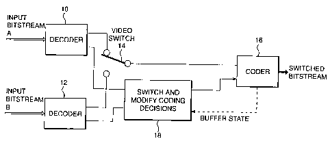
Figure 1 is a block diagram of a switch according to the present invention;
and
Figure 2 is a block diagram of apparatus for preconditioning a bitstream for
splice.
Figure 1 shows in block diagram form, apparatus for switching between two MPEG-
2
video bitstreams, denoted in the figure as bitstream A and bitstream B. Two
MPEG
decoders 10 and 12 are provided. The two decoders each produce two outputs; a
decoded
video signal, and a coding decision signal. The coding decision signal
contains all the
relevant information about how the corresponding bitstream was coded that can
be deduced
from the bitstream. This information includes, but is not limited to, the
following: picture
dimensions; frame rate; picture structure (frame-coded or field-coded);
picture type (I, P or
B); whether macroblocks are intra-coded
CA 02295754 1999-12-23
WO 99/04571 PCT/GB98/02121
-5-
or use prediction; whether forward, backward or bi-directional prediction is
used; motion vectors; quantiser visibility weighting matrices; quantiser step
and buffer state of a downstream decoder.
The two decoded video signals are switched in video switch 14 as if
they were conventional uncompressed signals and the output of the video
switch is sent to a coder 16. This is a special sort of MPEG-2 coder that
can make use of a coding decision signal as disclosed for example in
EP0765576 or W098/03017. This coder will reuse some or all of the
decisions taken by the coder or coders that created the input bitstreams, as
follows.
Block 18 serves to provide coding decisions to the coder 16. For
frames far away from the switching point, all of the coding decisions are
reused and block 18 merely serves to pass the coding decisions associated
with decoding of bitstream A or bitstream B, as appropriate. Doing this
causes the re-coding process to be near-transparent, i.e. the picture
obtained by decoding the output bitstream is virtually indistinguishable from
that which would be obtained by decoding the corresponding input bitstream
For frames near the switch point, block 18 modifies coding decisions
and the MPEG picture type may be changed on re-coding. The main
purpose of this is to modify the refresh strategy to be more suitable for the
switched bitstream. Typically an intra coded picture (I-picture) is used soon
after the switch point, to prevent prediction from occurring "across the cut".
More ingeniously, I-pictures in the input bitstreams may be "converted" to
non-intra pictures (typically P-pictures), in order to prevent too many 1-
pictures coming in close succession, which could cause the short-term bit
rate to be too high and underflow the buffer of a downstream decoder.
Under some circumstances (for instance when there is a large amount of
motion in the scene), an intra coded frame may be converted into an intra
coded field followed by a forward coded field (to do this the MPEG-2 picture
structure is converted from frame to field). This is an alternative method of
reducing the short-term bitrate.
The example set out below shows a case where one picture in bitstream
CA 02295754 1999-12-23 ~
WO 99/04571 PCT/GB98/02121
-6-
A, and two in bitstream B have had their picture type modified on re-coding.
These pictures are shown in a bold typeface (for clarity, the pictures are
shown in the order in which they are displayed at the decoder output, not
the order in which they appear in the bitstream):
switch point
InputA P B B I
; . . . . .
Input B . . . . ; B P B B! B B P
Switched output P B B P ; B I B B P B B P
The prediction mode and motion vectors are modified as necessary to
take into account any change in picture type, and to prevent predictions
from being made "across the cut". Often this involves a simplification; in the
above example, the B-picture following the switch point would usually
contain bi-directionally predicted macroblocks in input bitstream B, these
are modified to be forward predicted, and the backward vectors discarded.
However, where an I-picture is converted to a P-picture, new vectors will
need to be estimated, unless MPEG-2 concealment vectors were available
in the input bitstream.
The quantiser parameters are modified in order to control the number of
bits produced on re-coding. This is typically done by the rate controller in
any MPEG-2 coder, which monitors the buffer state of a downstream
decoder (actually it monitors the state of its own output buffer, which
mirrors
that of the decoder buffer).
The rate controller for this invention differs from a conventional one in
that the bit usage of the input bitstreams is conveyed via the coding
decisions, and is used to set targets for the number of bits to be produced
on re-coding. These targets are then used to determine the quantiser
parameters. Also, over a number of frames following the switch point, the
rate controller attempts to bring the buffer state of a downstream decoder to
match what it would have been if bitstream B had been sent directly to the
CA 02295754 1999-12-23
WO 99/04571 PCT/GB98/02121
-7-
decoder. Typically the number of bits required is set to be slightly lower
than the input bitstream. When the decoder buffer state matches, the rate
controller enters a "locked" mode in which the quantiser parameters (as well
as all other coding decisions) are kept exactly the same as in the input
bitstream. After this point, the switch is virtually transparent. Due to an
effect called "temporal masking", the level of noise in the pictures
immediately before and after the switch point can often be allowed to be
higher than at other times. The eye is distracted by the change in picture
material and fails to notice the additional noise. Thus the number of bits
used in these pictures may deliberately be made quite small, if this helps in
making the buffer state match as above.
Although this specific description has focused on the switching of
MPEG-2 bitstreams, many of the techniques are applicable for use with
other types of DCT-based compressed video bitstreams, such as JPEG,
ETSI and MPEG-1, or even non-DCT-based bitstreams, such as in wavelet
or fractal-based systems
The invention can easily be modified to cope with the case when
switching between compressed and non-compressed inputs; here the coder
makes use of the coding decisions in the compressed input, but makes its
own decisions when the non-compressed input is selected
The switch can be extended to incorporate a reduction in bitrate, in
other words, the rate of the output bitstream is lower than one or both of the
input bitstreams. For example, a lower bitrate may be used for transmission
to the viewer than is used for distribution from the studio to the
transmitter.
In such cases, the switch is not intended to be transparent, and there is no
need to attempt to match the downstream decoder's buffer state as above.
ln addition to performing simple switches, other video transitions may be
required. The most important of these is the cross-fade. MPEG coding of
cross-fading sequences tends to give poor quality pictures; this is due to the
difficulty in estimating motion vectors and poor performance of forward
prediction. This invention can be extended to perform cross-fades.
For this purpose, the described video switch takes the form of a video
= CA 02295754 1999-12-23 ~
WO 99/04571 PCT/GB98/02121
-8-
cross-fading device. It will be recognised that during the fade, decisions
from both input bitstreams are available for use in re-coding.
In one coding strategy, the decisions from bitstream A are used for the
first part of the fade, and for the last part, the decisions from bitstream B
are used. In an alternative strategy, the potential coding quality is assessed
separately using each set of decisions, and the better set chosen.
Temporal masking is not appropriate, as there is no sudden change
from one sequence to the other. However, the mixing of the sequences
tends to decrease visibility of quantisation noise, and the rate controller of
the coder can exploit this fact.
Some techniques of this invention can be used to precondition a
transport stream as part of a splicing device.
Referring now to Figure 2, this shows splicing from transport stream A
to transport stream B. Transport stream A is demultiplexed in transport
stream demultiplexer 20 to elementary bitstreams (for clarity, only the video
bitstream is shown). The video bitstream is decoded to video in the decoder
22 with coding decisions also being output. The video signal passes directly
to a video coder 24 which also receives the coding decisions after they
have passed through a "modify coding decisions" block 26. When many
frames from a splice, the video is re-coded with the same decisions and
remultiplexed in transport stream multiplexer 28; this will be transparent
under normal conditions. Near the time of splicing in transport stream
splicer 30, the number of bits produced will be adjusted to meet the buffer
constraints for splicing, by modifying the coding decisions in block 6,
typically by adjusting the quantiser parameters.
In addition to the above, the inputs must be synchronised to ensure that
splicing occurs on the correct picture type, and modifications are required to
the time stamps and clock reference information in the transport stream.
These aspects are not shown in the above diagram.
Another possible embodiment of the present invention is a non-real-time
edit conforming switch based in software. To speed up the operation of this,
some modifications may be made to the essentially hardware approach
CA 02295754 1999-12-23
WO 99/04571 PCT/GB98/02121
-9-
described thus far. Bitstreams may be directly copied when the switch is
effectively transparent. Only a partial decode - as far as the DCT domain -
may be performed under some circumstances, provided that the picture
type is not changed. This may lead to a small loss but acceptable loss in
quality.
It should be understood that this invention has been described by way of
examples only and that a wide variety of modifications are possible without
departing from the scope of the invention.